

Page 1
dept26
Products
Passive
Components
RF Switching
Products
Fiber Optic
Products
Active
Components
Power Meters
and Monitors
SatCom
Products
RF Safety
Test Solutions
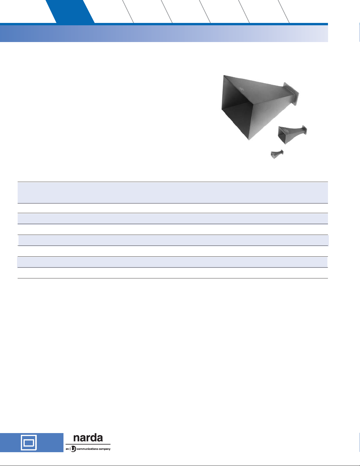
Waveguide Horns
50 Years of
Excellence
2.60-40 GHz
Standard Gain Horns
Primary Standard of Antenna Gain
·
7 Models Cover from 2.60 GHz to 40 GHz
·
Specifications
FREQUENCY WAVEGUIDE INPUT VSWR WEIGHT
RANGE MODEL BAND* SIZE COVER FLANGE (Max) lbs. Kg
(GHz) EQUIVALENT
2.60-3.95 644 S WR-284 UG-584/U 1.15 6 2.8
3.95-5.85 643 C WR-187 UG-407/U 1.15 2.3 1.1
5.4-8.20 642 XN WR-137 UG-441/U 1.15 1.0 0.5
8.20-12.4 640 X WR-90 UG-135/U 1.15 0.5 0.23
12.4-18 639 KU WR-62 UG-419/U 1.15 0.2 0.1
18-26.5 638 K WR-42 UG-595/U 1.15 0.2 0.1
26.5-40 V637 V WR-28 UG-599/U 1.15 0.1 0.05
*For a complete listing of all band letters and codes in use, refer to
Band Designation Table on page 176.
Patterns for all models in this series conform to the following
description: Beam width in E and H plane varies from 23° at the
highest frequency to 34° at the lowest frequency. Side lobes in
the H plane are all more than 20 dB down. First side lobes in the
E plane are 13 dB down, second side lobes are 18 dB down and
all other E plane lobes are more than 20 dB down.
Gain at Mid Frequency; 16.5 dB (with reference to isotropic radiation)
variation is 1.5 dB over total band about the mid band value.
See Waveguide Flange Data on page 188.
182
USA TEL: (1) 631 231-1700 • INT’L TEL: (1) 631 231-1390 • FAX (1) 631 231-1711
E-MAIL: nardaeast@L-3COM.com • www.nardamicrowave.com
435 MORELAND ROAD • HAUPPAUGE, NY 11788
Page 2
RF Safety
Test Solutions
SatCom
Products
Power Meters
and Monitors
Active
Components
Fiber Optic
Products
RF Switching
Products
Passive
Components
dept26
Products
50 Years of
Excellence
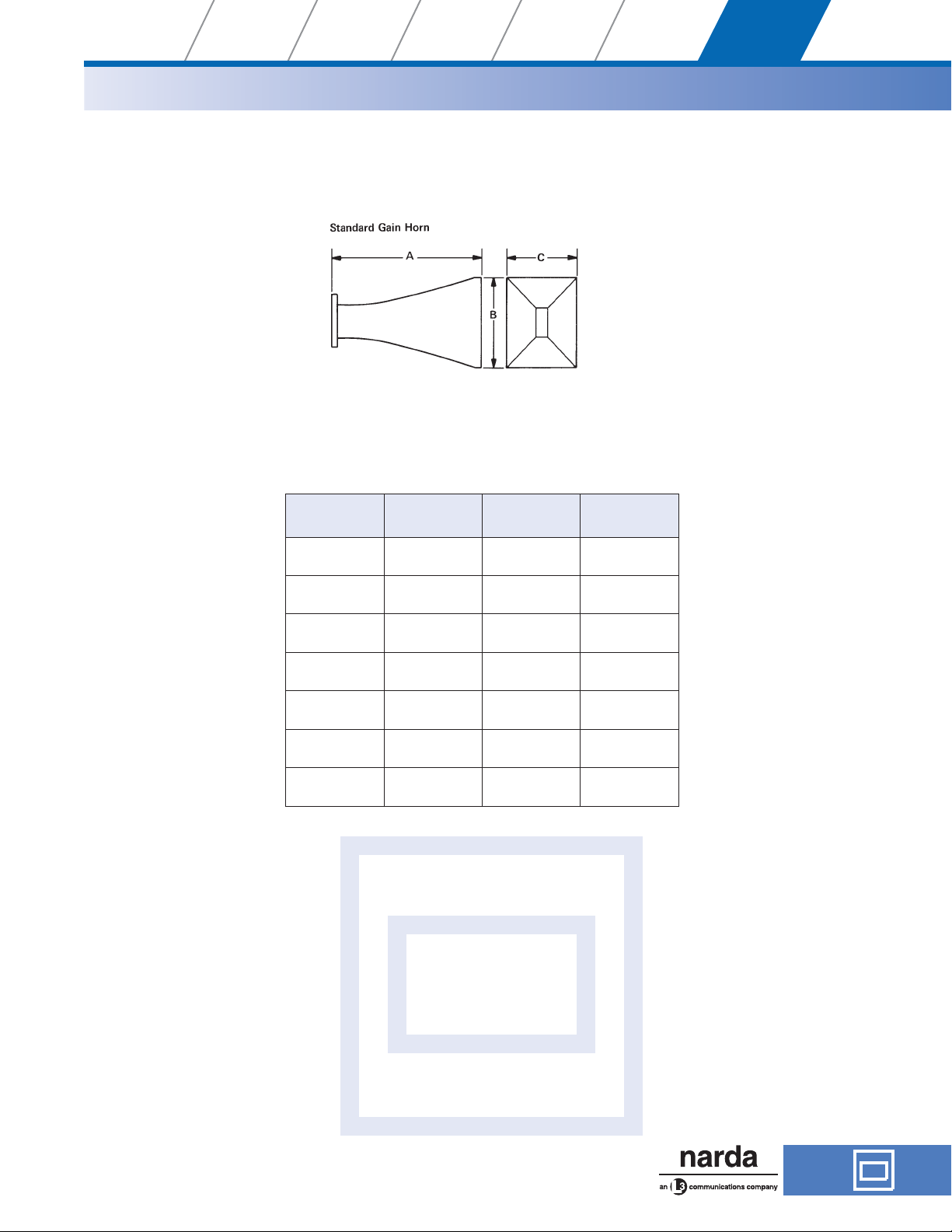
Outline Drawing
MODEL
V637
638
639
640
642
643
644
A
MAX
1.76
(44.7)
2.57
(65.2)
3.48
(88.3)
5.10
(129.5)
7.76
(197.1)
10.47
(265.9)
15.83
(402.1)
B
MAX
1.06
(26.9)
1.51
(38.3)
2.20
(55.8)
3.15
(80.01)
4.67
(118.6)
6.34
(161.0)
9.55
(242.6)
Waveguide Horns
C
MAX
.82
(20.8)
1.16
(29.4)
1.73
(43.9)
3.40
(60.96)
3.53
(89.6)
4.80
(121.9)
7.25
(184.2)
Dimensions in parentheses are in millimeters and for reference only.
All dimensions max. unless otherwise specified.
435 MORELAND ROAD • HAUPPAUGE, NY 11788
USA TEL: (1) 631 231-1700 • INT’L TEL: (1) 631 231-1390 • FAX (1) 631 231-1711
E-MAIL: nardaeast@L-3COM.com • www.nardamicrowave.com
183
Page 3
dept26
Products
Passive
Components
RF Switching
Products
Fiber Optic
Products
Active
Components
Power Meters
and Monitors
SatCom
Products
RF Safety
Test Solutions
Waveguide Horns
Reference Guide
WAVEGUIDE TO COAXIAL ADAPTERS FOR STANDARD GAIN HORN
STANDARD GAIN
HORN MODEL
644 614A —
643 613A —
642 612A 4602
640 601A 4601
639 609 4609
638 — 4608B
V637 — V4607
WAVEGUIDE TO COAXIAL TYPE
N - FEMALE MODEL
50 Years of
Excellence
ADAPTER SMA/3.5/2.9
FEMALE MODEL
184
USA TEL: (1) 631 231-1700 • INT’L TEL: (1) 631 231-1390 • FAX (1) 631 231-1711
E-MAIL: nardaeast@L-3COM.com • www.nardamicrowave.com
435 MORELAND ROAD • HAUPPAUGE, NY 11788
Page 4

RF Safety
FREQUENCY (GHz)
Test Solutions
SatCom
Products
Power Meters
and Monitors
Active
Components
Fiber Optic
Products
RF Switching
Products
Passive
Components
dept26
Products
50 Years of
Excellence
GAIN (dB)
19.0
19.0
18.0
17.0
16.0
15.0
14.0
ABSOLUTE GAIN CALIBRATION
NARDA MODEL V637 STANDARD GAIN HORN
26.0
28.0 30.0 32.0 34.0 36.0 38.0 40.0
ABSOLUTE GAIN CALIBRATION
NARDA MODEL 638 STANDARD GAIN HORN
Waveguide Horns
GAIN (dB)
GAIN (dB)
18.0
17.0
16.0
15.0
14.0
19.0
18.0
17.0
16.0
19.018.0
20.0 21.0 22.0 23.0 24.0 25.0 26.0 27.0
ABSOLUTE GAIN CALIBRATION
NARDA MODEL 639 STANDARD GAIN HORN
15.0
14.0
435 MORELAND ROAD • HAUPPAUGE, NY 11788
USA TEL: (1) 631 231-1700 • INT’L TEL: (1) 631 231-1390 • FAX (1) 631 231-1711
E-MAIL: nardaeast@L-3COM.com • www.nardamicrowave.com
13.012.0
14.0 15.0 16.0 17.0 18.0
185
Page 5

dept26
FREQUENCY (GHz)
Products
Passive
Components
RF Switching
Products
Fiber Optic
Products
Active
Components
Power Meters
and Monitors
SatCom
Products
RF Safety
Test Solutions
Waveguide Horns
GAIN (dB)
19.0
18.0
17.0
16.0
15.0
14.0
ABSOLUTE GAIN CALIBRATION
NARDA MODEL 640 STANDARD GAIN HORN
8.58.0
9.0 9.5 10.0 10.5 11.0 11.5 12.0 12.5
50 Years of
Excellence
186
ABSOLUTE GAIN CALIBRATION
NARDA MODEL 643 STANDARD GAIN HORN
19.0
18.0
17.0
GAIN (dB)
16.0
15.0
14.0
4.0 4.2 4.4 4.6 4.8 5.0 5.2 5.4 5.6 5.8
USA TEL: (1) 631 231-1700 • INT’L TEL: (1) 631 231-1390 • FAX (1) 631 231-1711
E-MAIL: nardaeast@L-3COM.com • www.nardamicrowave.com
435 MORELAND ROAD • HAUPPAUGE, NY 11788
Page 6

RF Safety
FREQUENCY (GHz)
Test Solutions
SatCom
Products
Power Meters
and Monitors
Active
Components
Fiber Optic
Products
RF Switching
Products
Passive
Components
dept26
Products
50 Years of
Excellence
ABSOLUTE GAIN CALIBRATION
NARDA MODEL 644 STANDARD GAIN HORN
19.0
18.0
17.0
GAIN (dB)
16.0
15.0
14.0
2.65 2.85 3.05 3.25 3.45 3.65 3.85
Waveguide Horns
435 MORELAND ROAD • HAUPPAUGE, NY 11788
USA TEL: (1) 631 231-1700 • INT’L TEL: (1) 631 231-1390 • FAX (1) 631 231-1711
E-MAIL: nardaeast@L-3COM.com • www.nardamicrowave.com
187
Page 7

dept26
Products
Passive
Components
RF Switching
Products
Fiber Optic
Products
Active
Components
Power Meters
and Monitors
SatCom
Products
RF Safety
Test Solutions
Waveguide Flange Data
LS BAND
50 Years of
Excellence
L BAND
X BAND
BAND* TYPE A B C D HOLE DIA.
X UG-39/U .640 .610 1.625 .813 .169
XB UG-51/U .737 .676 1.875 .938 .169
K UG-595/U .320 .335 .875 .438 .116
KU UG-419/U .478 .497 .313 .656 .144
V UG-599/U .250 .265 .750 .375 .116
K, V, Q, M, E BAND
BAND* TYPE A B C
K UG-425/U 1.125 .937 .331
V UG-381/U 1.125 .937 .331
Q UF-383/U 1.125 .937 .331
M UF-385/U .75 .562 .199
E UG-387/U .75 .562 .199
XB BAND
K BAND
XN, C, S BAND
BAND* TYPE A HOLE DIA.
S UG-53/U 5.313 .257
C UG-149A/U 3.625 .199
KU BAND
V BAND
*For a complete listing of all band letters and codes in use,
refer to Band Designation Table on page 176.
188
USA TEL: (1) 631 231-1700 • INT’L TEL: (1) 631 231-1390 • FAX (1) 631 231-1711
E-MAIL: nardaeast@L-3COM.com • www.nardamicrowave.com
435 MORELAND ROAD • HAUPPAUGE, NY 11788
 Loading...