

Page 1
Programmable
DC Electronic Load
The Chroma Electronic Loads 63200 series are
designed for DC power source, power electron-
ic devices and components testing. The high
power rating, parallel and synchronization
capabilities make them the ideal tool for testing
the high power UUT such as SMR,UPS, bat-
tery, and fuel cell.
The 63200 series offers 10 different models
with power range from 2600 watts to 15600
watts, current from 50A to 1000A and up to
500V input voltage. The 4 load modes setup
provide different load simulations for various
application occasions. The CC/CR modes are
designed to test constant voltage type of power
supply. CV mode is used to test battery charger
and current source, while CP mode is ideal for
battery testing by simulating the real discharge
curve.
The 63200 series can draw its rated current
under very low voltage (1V typical) even under
the highest specified slew rate. This unique fea-
ture guarantees the best loading performance
to a low voltage power supply.
With the unique external waveform simulation
and Master /Slave control capability, the 63200
series electronic loads allow users to parallel
and synchronize more than one load together
from an internal or external loading control sig-
nal. This feature provides unlimited load simula-
tion and the possibility of power expansion.
The 63200 series also supply necessary mea-
surement functions and short circuit simulation
that extend the test capability for even the most
demanding engineering tests and ATE applica-
tions.
With the LCD display and rotary knob, the
63200 electronic loads offer versatile front
panel operations. Users are able to control the
63200 family remotely via GPIB, RS-232C,RS-
485 or APG (Analog Programming) interface.
Chroma 63200 series loads are built in fan
speed control to minimize the audio noise. The
self-diagnosis routine and the full protections
against OPP, OCP, OVP, OTP and reverse
polarity ensure the best quality and reliability.
PROGRAMMABLE
DC ELECTRONIC LOAD
MODEL 63200 SERIES
RS-485
MODEL 63200 SERIES
Key Features:
Power Rating:
2600W,5200W,6500W,10400W,
14500W, 15600W
Voltage range: 1-80V/ 2.5-500V
Current range: Up to 1000A
CC, CR, CV, CP load modes
Master/Slave paralleling control mode,
allow synchronous load control under
static and dynamic loading mode
Dynamic loading: Up to 20KHz
Only need 1V to draw rated current
Programmable slew rate, up to 41A/uS
Measurement: Voltage / Current
Power/ Resistance
Large LED/LCD display
External loading waveform simulation
Short circuit simulation and short
circuit current measurement
Full protection: OP,OC,OV,OT and
reverse protection
Versatile remote controller
GPIB& RS-232C; RS-485 interface
Surge load capability
Battery discharge timer
Page 2
and therefore can test if the battery charger has correct charging current corresponding to its own output, or more precisely, the battery voltage. If the UUT is battery, the electronic load is able to simulate the behavior of the device that uses the
battery. For most of the electronic and electrical devices, their power consumption patterns are more likely constant power devices.
Consequently, CP mode simulation will be essential for a battery discharge load.
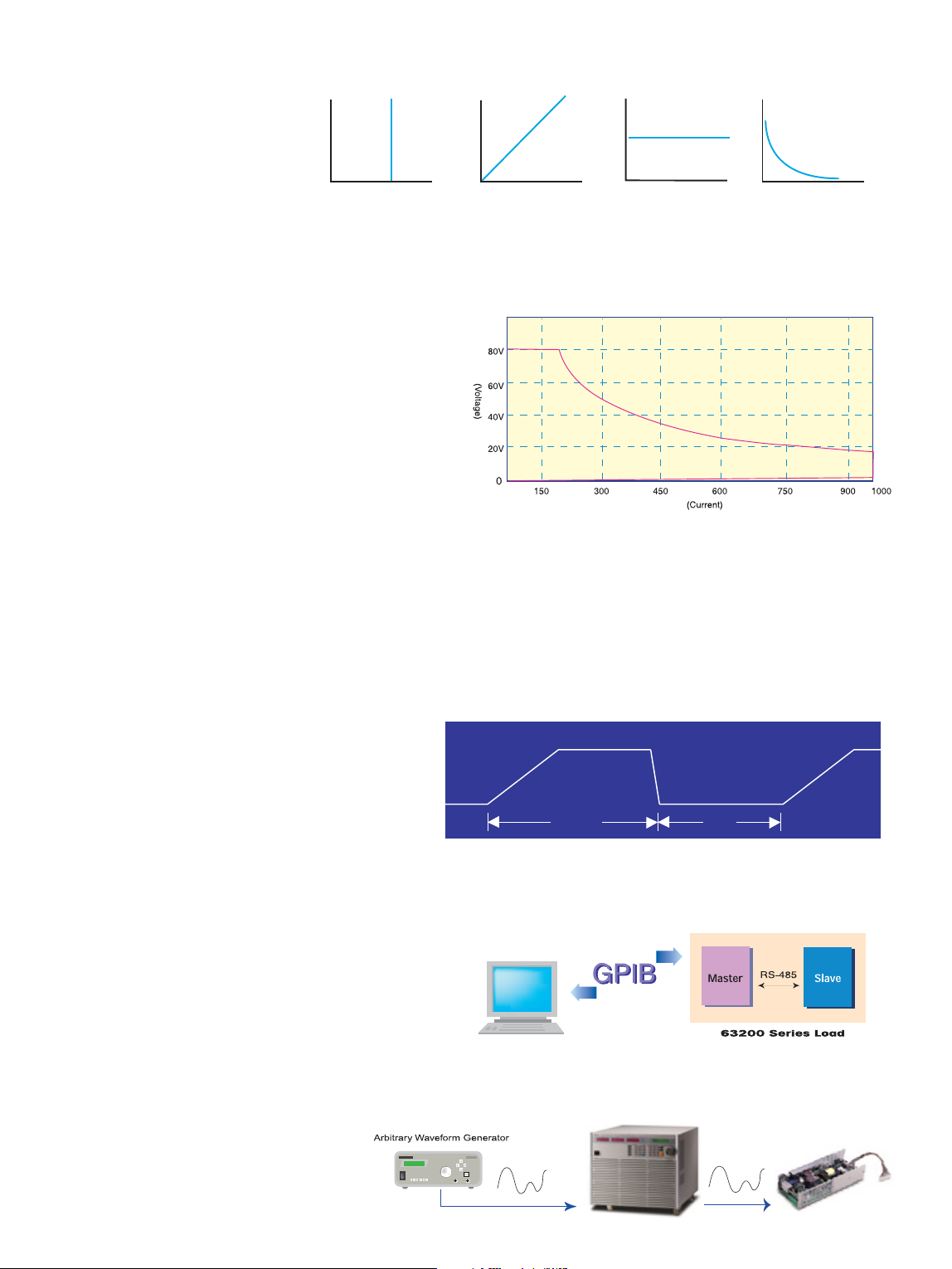
2. LOW VOLTAGE OPERATING CHARACTERISTICS
For high power load, its high loading current may cause dramatic line
drop between UUT and load terminal due to the line impedance of
cabling. So, the lower operating voltage allows the 63200 series
loads to draw sufficient current from a low volt output power supply
directly.
Meanwhile, 63200 series loads use current close loop design, and
connect all power MOSFET devices in parallel to insure high accuracy load control with minimum drift less than 0.15% of the current setting. The MOSFET technology accomplishes the input impedance to
a minimum that enables the load to draw very high current even at
very low voltage. For example, model 63209 is capable of drawing
1000A at only 1V input.
3. MEASUREMENTS
Chroma 63200 series are built in the15-bits precision A/D converter, thus can achieve 0.05%F.S., 0.1%F.S. and 0.3%F.S. accuracy for voltage,
current and power measurement respectively. And they can be shown simultaneously on three big LED displays for user's convenience. In
additional to standard measurements, they also provide voltage and current monitor outputs, which are useful when user needs to monitor the
voltage and current waveform via scope.
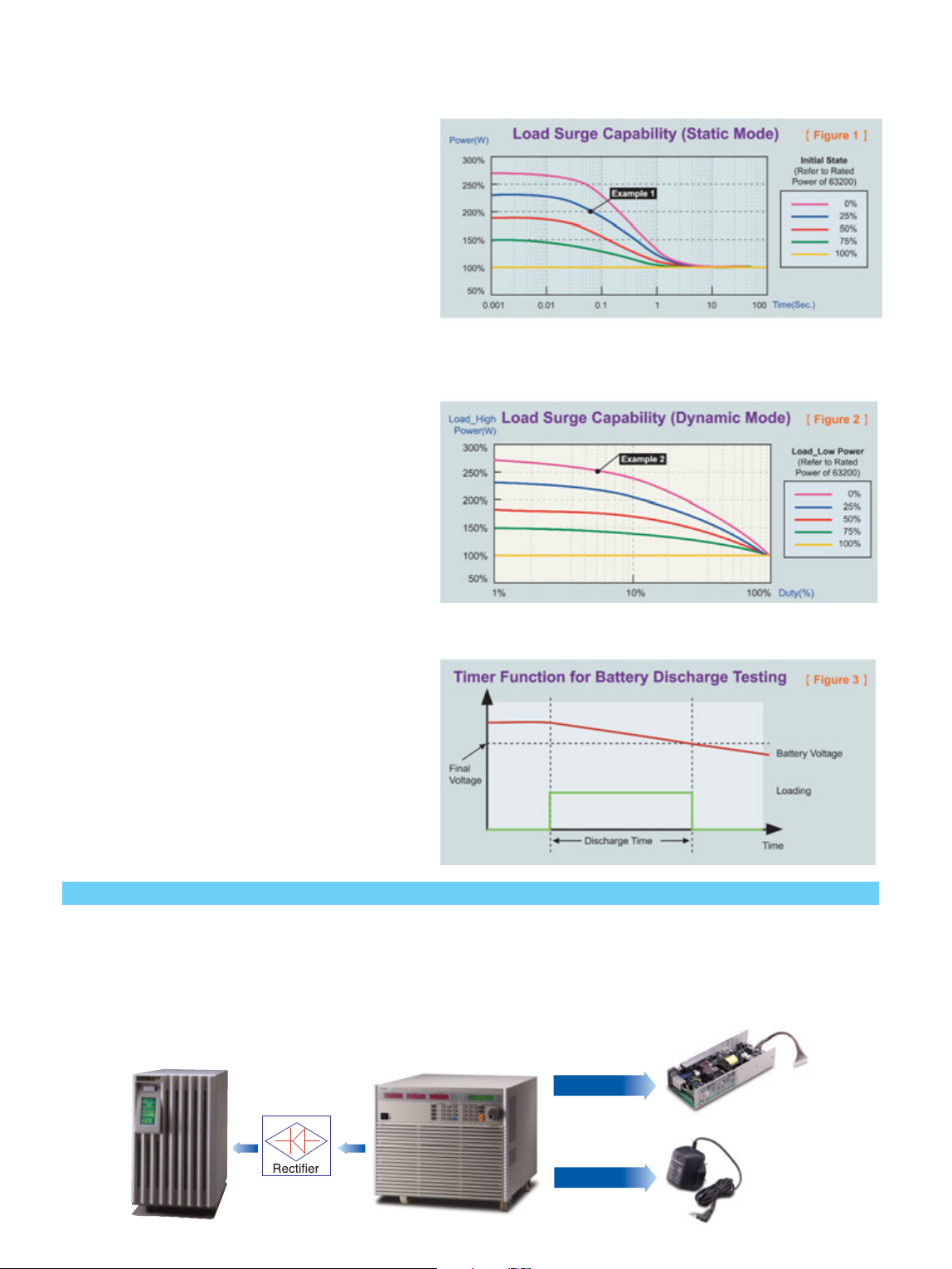
4. DYNAMIC LOADING AND CONTROL
Modern electronic devices operate at very high speed, thus,it is
important for an electronic load to perform well in the transient
and dynamic response of power devices. To satisfy these testing applications, the 63200 loads offer high speed, programmable dynamic load simulation and control capability ever
achieved before. The figure below shows the programmable
parameters of the 63200 load modules. The programmable slew rate makes the simulation of transient load change demanded by the requirement of real life application possible. The internal waveform generator of 63200 is capable of producing maximum slew rate at 25A/uS (63208),
and dynamic cycling up to 20KHz. Its dedicated remote load senses and controls circuit guarantee the minimum waveform distortion during
continuous load changes.
5. MASTER / SLAVE PARALLEL CONTROL
When higher power is required,it is common to parallel two electronic loads together to draw higher current. 63200 series high
power loads have smart Master / Slave control mode. When the
loads are set to Master / Slave mode, users can program the loading (CC mode only) on master unit. The loading current values of
the slave units will be calculated and downloaded by master unit automatically. In short, unlike the traditional design, users may consider several
load units that work under Master / Slave mode as a single load unit. It simplifies the user operation dramatically.
6. EXTERNAL LOADING WAVEFORM
SIMULATION
The 63200 series electronic loads can be controlled by external analog control signal, which is
generated by any kind of signals or arbitrary
waveform generator. Thus, it is capable of simulating any loading waveforms observed in the field.
The CC and CR mode loading simulation is helpful to test whether the output
voltage of the UUT remains stable or
regulated under different loading current or resistance conditions. For battery chargers, CV mode may help to
change the output voltage of a charger
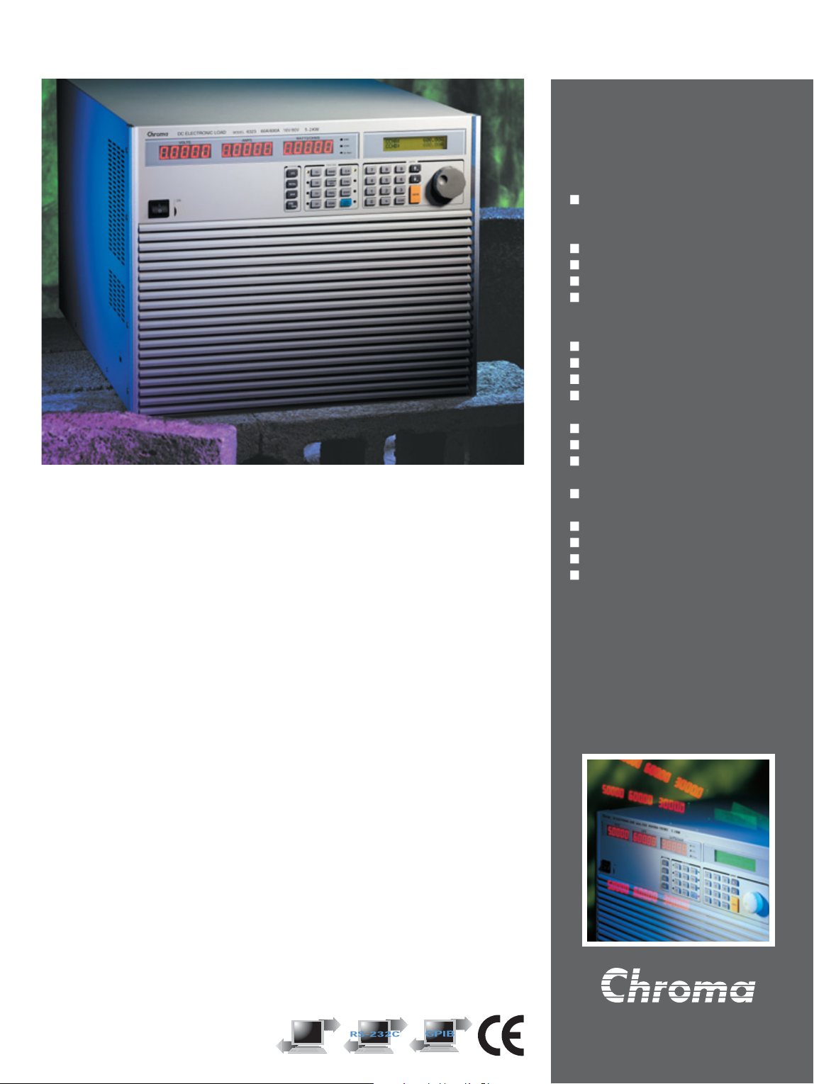
1. APPLICATION SPECIFIC LOAD SIMULATION
Chroma electronic loads 63200 series provide constant current, constant resistance, constant voltage and constant power modes for various
application requirements.
V
I
V
I
V
I
V
I
Constant current
Constant resistance
Constant voltage
Constant power
Model 63209(15600W) input characteristics
Rise rate
Load 1
Fall rate
Load 2
T1 T2
XCL,;LB,N;.B’MBNCLV LLXCLMLVMKCMBBV
C545
VB56566NM GH2333
32233 115666
XZHGCZCKVKCKVCXXMLXMCKMKC
XK CV GH VB CV VB
ZXZCXZVCX
CX
CX
CX
CX
XCXK
VCVV/
HJJ
XCXVCVV
XCXVCVV
XCXVCVV
CX
CVC XD
Page 3
8. SURGE LOAD CAPABILITY
Chroma’s 63200 Series DC Loads provide a unique surge
load simulation capability which allows users to overdrive
the loads up to 2.7 times their rated power for short periods.
This feature is ideal when the average power require by the
UUT is low compared to short-term peak power demands.
Plasma Display Panel (PDPs) testing is one typical application, others include battery 3C discharge, breaker & fuse
over rating (300% to 1000%) tests, car engine startup simulation and DC motor startup simulation.
The amount of surge loading available using the 63200
loads is related to the initial loading conditions. Figures 1
and 2 show the relationship of initial state (Load_Low under
Dynamic mode) and the maximum acceptable overdrive
power. Under this operation, the load will display an Over
Power Protection Alarm (OPP) and will disable the load current if the user violates the maximum surge load capability
showed in the figures.
Note 1 :
The Initial state under Static Mode should last at least 1 second.
Note 2 :
This surge load capability will be regulated by the temperature de-rating characteristics. (Refer to Note 1 in Specifications)
Note 3 :
Examples below assume the use of the Model 63201 load with a continuous rating of 2600W/300A/1-80VDC
9. TIMER FUNCTION FOR BATTERY
DISCHARGE TESTING
The 63200 Loads include unique timing & measurement
function allowing for precision time settings and measurements in the range of 1s to 99999s. This feature allows
users to set a final voltage & timeout value for battery discharge testing and similar applications.
For Example, Figure 3 below shows that the 63200’s internal
timer can be initiated automatically when the battery voltage
falls below a preset value. The timer will continue counting
until the second preset voltage value is reached.
Example 1: STATIC LOADING
The Model 63201 can be overdriven to approximately 5200W (200% of its rated continuous power rating) for 6.0 ms seconds when the starting power is 650W (25% of its
rated power). This is represented by DOT on the blue curve in Figure 1.
Example 2: DYNAMIC LOADING
The Model 63201 is capable of a zero – to- 6500W (250%) pulse at a duty cycle of 5%.
This is represented by the DOT on the purple curve in Figure 2.
7. SHORT CIRCUIT SIMULATION
63200 series electronic loads can also simulate short circuit condition. Owing to this capability, it can short DC power source or any power supplies that have built in current limit function, and measure their short circuit currents. So that users can verify if the UUT current limit is functional.
APPLICATIONS
1. POWER SUPPLY TESTING
Power supplies have played a critical role on electrical and electronic devices. They are diversified into several different configurations for different
applications. For example, AC/AC power supplies are for UPS and AVR, AC/DC power supplies are for PC power supplies, and DC/AC power
supplies are for inverters that transfer battery power to AC for home appliances. As to DC/DC converters, they are widely used in battery powered devices such as cellular phones and laptop computers. With four different load modes, Chroma 63200 series electronic loads are capable
of testing all sorts of DC output power supplies directly or via rectifier, they can also be used to test the AC output power supplies.
CC & CR Mode
CV Mode
A/ D Power supply
D/ D Converter
Battery charger
UPS/AVR
Page 4

2. ELECTRONIC & ELECTRICAL DEVICES TESTING
Almost all modern electronic and electrical devices are built in with
power supply. Therefore, DC electronic load is an important instrument for these devices during R/D and Q/A phases. For example,
A/D, D/D and D/A stages are normally integrated in a UPS.
Consequently, Chroma 63200 electronic loads are helpful to test the
internal A/D and D/D boards of the UPS.
3. BATTERY TESTING
For most of the electronic and electrical devices, their power consumption patterns are constant power. Therefore, the CP mode in 63200
series electronic loads is ideal to use as a discharge load for battery testing.
4. SYSTEM INTEGRATION
Chroma 63200 series electronic loads provide GPIB, RS-232C and RS-485 PC controllable interfaces. The external waveform simulation and
voltage / current monitoring capability make Chroma 63200 family ideal for automatic system integration.
I
V
I
V
I
V
Discharge by CR mode
Discharge by CC mode
Discharge by CP mode
1. Power Switch
2. LED Display:
Voltage read back.
3. LED Display:
Current/ ohm read back.
4. LED Display:
Power read back.
5. LCD Display:
For setting and editing.
6. Rotary knob:
To adjust the loading and parameter setting.
7. Numeric key:
For data setting.
8. Function key:
To select load mode, control mode, and define the
reading specification.
9. System key:
For system config and data store, recall.
10. Load terminal
11. Voltage sense terminal
12. RS-485 connector
13. GPIB connector
14. RS-232C connector
15. Voltage monitor output:
Analog output which indicates the voltage waveform.
16. Current monitor output:
Analog output which indicates the current waveform.
17. External V reference:
External programming voltage input.
2
12
4 6
7
3
8
5
9
1
13
10
11
14
15
17
16
Model: 63203, 63204
PANEL DESCRIPTION
Page 5

Model 63201 63202 63203
Power*1 260W 2600W 260W 2600W 520W 5200W
Current 0-30A 0-300A 0-5A 0-50A 0-60A 0-600A
Voltage 1-80V 2.5-500V 1-80V
Min. Operating Voltage 1V@30A 1V@300A 2.5V@5A 2.5V@50A 1V@60A 1V@600A
Constant Current Mode
Range 0-30A 0-300A 0-5A 0-50A 0-60A 0-600A
Resolution 7.5mA 75mA 1.25mA 12.5mA 15mA 150mA
Accuracy 0.1%+0.1%F.S. 0.2%+0.1%F.S. 0.1%+0.1%F.S. 0.2%+0.1%F.S. 0.1%+0.1%F.S. 0.2%+0.1%F.S.
Constant Resistance Mode
Range 0.005-20ohm 0.25-1000ohm 0.25-1000ohm 10-40000ohm 0.0025-10ohm 0.125-500ohm
Resolution 12bits 12bits 12bits 12bits 12bits 12bits
Accuracy*2 0.6mho+0.35% 0.9mho+0.1% 0.012mho+0.35% 0.04mho+0.1% 1.2mho+0.35%*4 1.2mho+0.1%
Accuracy*3 (Vin>7V) 0.6mho+0.35% 0.012mho+0.35% 0.012mho+0.35% 112.5u mho+0.35% 1.2mho+0.35% 0.024mho+0.35%
Constant Voltage Mode
Range 1-16V 1-80V 2.5-125V 2.5-500V 1-16V 1-80V
Resolution 4mV 20mV 31mV 125mV 4mV 20mV
Accuracy 0.05%+0.1%F.S. 0.05%+0.1%F.S. 0.05%+0.1%F.S. 0.05%+0.1%F.S. 0.05%+0.1%F.S. 0.05%+0.1%F.S.
Constant Power Mode
Range 0.6-260W 6-2600W 0.625-260W 6.25-2600W 1.2-520W 12-5200W
Resolution 7.5mW 75mW 3.125mW 31.25mW 22.5mW 225mW
Accuracy 0.5%+0.5%F.S. 0.5%+0.5%F.S. 0.5%+0.5%F.S. 0.5%+0.5%F.S. 0.5%+0.5%F.S. 0.5%+0.5%F.S.
Dynamic Mode
Timing
T1&T2 0.025-10mS 1mS-30S 0.025-10mS 1mS-30S 0.025-10mS 1mS-30S
Resolution 1µS 1mS 1µS 1mS 1µS 1mS
Accuracy 1µS+100ppm 1mS+100ppm 1µS+100ppm 1mS+100ppm 1µS+100ppm 1mS+100ppm
Slew Arte 5mA-1.25A/µS 50mA-12.5A/µS 0.8mA-0.2A/µS 8mA-2A/µS 10mA-2.5A/µS 100mA-25A/µS
Resolution 5mA/µS 50mA/µS 0.8mA/µS 8mA/µS 10mA/µS 100mA/µS
Min. Rise Time 20 µS (typical) 24 µS (typical) 20 µS (typical)
Current
Range 0-30A 0-300A 0-5A 0-50A 0-60A 0-600A
Resolution 7.5mA 75mA 1.25mA 12.5mA 15mA 150mA
Accuracy 0.4%F.S. 0.4%F.S. 0.4%F.S.
Measurement
Voltage Read Back
Range 0-16V 0-80V 0-125V 0-500V 0-16V 0-80V
Resolution 15bits 15bits 15bits 15bits 15bits 15bits
Accuracy 0.05%+0.05%F.S. 0.05%+0.05%F.S. 0.05%+0.05%F.S.
Current Read Back
Range 0-30A 0-300A 0-5A 0-50A 0-60A 0-600A
Resolution 15bits 15bits 15bits 15bits 15bits 15bits
Accuracy 0.1%+0.1%F.S. 0.1%+0.1%F.S. 0.1%+0.1%F.S.
Power Read Back
Range 0-260W 0-2600W 0-260W 0-2600W 0-520W 0-5200W
Resolution 15bits 15bits 15bits 15bits 15bits 15bits
Accuracy 0.3%+0.3%F.S. 0.3%+0.3%F.S. 0.3%+0.3%F.S.
General
Short Circuit
Current 30A 300A 5A 50A 60A 600A
Size(mm) 440(W)x 177(H)x 644(D) 440(W)x 177(H)x 644(D) 440(W)x 353(H)x 644(D)
Weight 35kg 35kg 58kg
Safety & EMC CE CE CE
Selection Guide :
Model 63208 / 63209 / 63210
Model 63206 / 63207
Model 63203 / 63204
Model
63201 / 63202
Model 63205
SPECIFICATIONS
2600W 5200W 6500W 10400W 14500W 15600W
80V 63201 63203 63205 63206/63207 -- 63208/63209
500V 63202 63204 -- -- 63210 --
Powe r
Model
Voltage
Page 6

Model 63204 63205 63206
Power*1 520W 5200W 650W 6500W 1040W 10400W
Current 0-10A 0-100A 0-18A 0-180A 0-60A 0-600A
Voltage 2.5-500V 1-80V 1-80V
Min. Operating Voltage 2.5V@10A 2.5V@100A 1V@18A 1V@180A 1V@60A 1V@600A
Constant Current Mode
Range 0-10A 0-100A 0-18A 0-180A 0-60A 0-600A
Resolution 2.5mA 25mA 4.5mA 45mA 15mA 150mA
Accuracy 0.1%+0.1%F.S. 0.2%+0.1%F.S. 0.1%+0.2%F.S. 0.1%+0.2%F.S. 0.1%+0.2%F.S. 0.1%+0.2%F.S.
Constant Resistance Mode
Range 0.125-500ohm 5-20000ohm 0.008-32ohm 0.4-1600ohm 0.0025-10ohm 0.125-500ohm
Resolution 12bits 12bits 12bits 12bits 12bits 12bits
Accuracy*2 0.024mho+0.35% 0.08mho+0.1% 0.375mho+0.35% 0.75mho+0.1% 1.2mho+0.35%*4 1.2mho+0.1%
Accuracy*3 (Vin>7V) 0.024mho+0.35% 225u mho+0.35% 0.375mho+0.35% 0.075mho+0.35% 1.2mho+0.35% 0.024mho+0.35%
Constant Voltage Mode
Range 2.5-125V 2.5-500V 1-16V 1-80V 1-16V 1-80V
Resolution 31mV 125mV 4mV 20mV 4mV 20mV
Accuracy 0.05%+0.1%F.S. 0.05%+0.1%F.S. 0.05%+0.1%F.S. 0.05%+0.1%F.S. 0.05%+0.1%F.S. 0.05%+0.1%F.S.
Constant Power Mode
Range 1.25-520W 12.5-5200W 0.36-650W 3.6-6500W 1.2-1040W 12-10400W
Resolution 6.25mW 62.5mW 4.6mW 46mW 22.5mW 225mW
Accuracy 0.5%+0.5%F.S. 0.5%+0.5%F.S. 0.5%+0.5%F.S. 0.5%+0.5%F.S. 0.5%+0.5%F.S. 0.5%+0.5%F.S.
Dynamic mode
Timing
T1&T2 0.025-10mS 1mS-30S 0.025-10mS 1mS-30S 0.025-10mS 1mS-30S
Resolution 1µS 1mS 1µS 1mS 1µS 1mS
Accuracy 1µS+100ppm 1mS+100ppm 1µS+100ppm 1mS+100ppm 1µS+100ppm 1mS+100ppm
Slew Arte 1.6mA-0.4A/µS 16mA-4A/µS 3mA-0.75A/µS 30mA-7.5A/µS 10mA-3A/µS 100mA-25A/µS
Resolution 1.6mA/µS 16mA/µS 3mA/µS 30mA/µS 10mA/µS 100mA/µS
Min. Rise Time 24 µS (typical) 15 µS (typical) 15 µS (typical)
Current
Range 0-10A 0-100A 0-18A 0-180A 0-60A 0-600A
Resolution 2.5mA 25mA 4.68mA 46.8mA 15mA 150mA
Accuracy 0.4%FS 0.4%FS 0.4%FS
Measurement
Voltage Read Back
Range 0-125V 0-500V 0-16V 0-80V 0-16V 0-80V
Resolution 15bits 15bits 15bits 15bits 15bits 15bits
Accuracy 0.05%+0.05%F.S. 0.05%+0.05%F.S. 0.05%+0.05%F.S.
Current Read Back
Range 0-10A 0-100A 0-18A 0-180A 0-60A 0-600A
Resolution 15bits 15bits 15bits 15bits 15bits 15bits
Accuracy 0.1%+0.1%F.S. 0.1%+0.1%F.S. 0.1%+0.1%F.S.
Power Read Back
Range 0-520W 0-5200W 0-650W 0-6500W 0-1040W 0-10400W
Resolution 15bits 15bits 15bits 15bits 15bits 15bits
Accuracy 0.3%+0.3%F.S. 0.3%+0.3%F.S. 0.3%+0.3%F.S.
General
Short Circuit
Current 10A 100A 18A 180A 60A 600A
Size (mm) 440(W)x 353(H)x 644(D) 440(W)x 310(H)x 644(D) 440(W)x 443.7(H)x 644(D)
Weight 58kg 64kg 90kg
Safety & EMC CE CE CE
Series
SPECIFICATIONS
Page 7

Model 63207 63208 63209 63210
Power*1 1040W 10400W 1560W 15600W 1560W 15600W 1450W 14500W
Current 0-30A 0-300A 0-60A 0-600A 0-100A 0-1000A 0-15A 0-150A
Voltage 1-80V 1-80V 1-80V 2.5-500V
Min. Operating Voltage 1V@30A 1V@300A 1V@60A 1V@600A 1V@100A 1V@1000A 2.5V@15A 2.5V@150A
Constant Current Mode
Range 0-30A 0-300A 0-60A 0-600A 0-100A 0-1000A 0-15A 0-150A
Resolution 9.3mA 75mA 15mA 150mA 31.25mA 250mA 3.75mA 37.5mA
Accuracy 0.1%+0.2%F.S. 0.1%+0.2%F.S. 0.1%+0.2%F.S. 0.1%+0.2%F.S. 0.1%+0.2%F.S. 0.1%+0.2%F.S. 0.1%+0.1%F.S 0.2%+0.1%F.S
Constant Resistance Mode
Range 0.005-20ohm 0.25-1000ohm 0.0025-10ohm 0.125-500ohm 0.0015-6ohm 0.075-300ohm 0.083-333ohm 3.3-13200ohm
Resolution 12bits 12bits 12bits 12bits 12bits 12bits 12bits 12bits
Accuracy*2 0.6mho+0.35% 0.9mho+0.1% 1.2mho+0.35%*4 1.2mho+0.1% 1.2mho+0.35%*4 1.2mho+0.1% 0.036mho+0.35% 0.092mho+0.1%
Accuracy*3(Vin>7V) 0.6mho+0.35% 0.012 mho+0.35% 1.2mho+0.35% 0.024mho+0.35% 1.2mho+0.35% 0.024mho+0.35% 0.036mho+0.35% 337.5u mho+0.35%
Constant Voltage Mode
Range 1-16V 1-80V 1-16V 1-80V 1-16V 1-80V 2.5-125V 2.5-500V
Resolution 4mV 20mV 4mV 20mV 4mV 20mV 31mV 125mV
Accuracy 0.05%+0.1%F.S. 0.05%+0.1%F.S. 0.05%+0.1%F.S. 0.05%+0.1%F.S. 0.05%+0.1%F.S. 0.05%+0.1%F.S. 0.05%+0.1%FS 0.05%+0.1%FS
Constant Power Mode
Range 0.744-1040W 6-10400W 1.2-1560W 12-15600W 2.5-1560W 20-15600W 5-1450W 50-14500W
Resolution 9.3mW 75mW 22.5mW 225mW 31.255mW 250mW 25mW 250mW
Accuracy 0.5%+0.5%F.S. 0.5%+0.5%F.S. 0.5%+0.5%F.S. 0.5%+0.5%F.S. 0.5%+0.5%F.S. 0.5%+0.5%F.S. 0.5%+0.5%FS 0.5%+0.5%FS
Dynamic Mode
Timing
T1&T2 0.025-10mS 1mS-30S 0.025-10mS 1mS-30S 0.025-10mS 1mS-30S 0.025-10mS 1mS-30S
Resolution 1µS 1mS 1µS 1mS 1µS 1mS 1uS 1mS
Accuracy 1µS+100ppm 1mS+100ppm 1µS+100ppm 1mS+100ppm 1µS+100ppm 1mS+100ppm 1uS+100ppm 1mS+100ppm
Slew arte 6mA-1.5A/µS 50mA-12.5A/µS 12mA-3A/µS 100mA-25A/µS 20mA-5A/µS 166mA-41.6A/µS 3mA-0.75A/µS 25mA-6A/µS
Resolution 6mA/µS 50mA/µS 12mA/µS 100mA/µS 20mA/µS 166mA/µS 3mA/uS 25mA/uS
Min. Rise Time 15 µS (typical) 15 µS (typical) 15 µS (typical) 24 µS (typical)
Current
Range 0-30A 0-300A 0-60A 0-600A 0-100A 0-1000A 0-15A 0-150A
Resolution 9.37mA 75mA 15mA 150mA 31.25mA 250mA 3.75mA 37.5mA
Accuracy 0.4%FS 0.4%FS 0.4%FS 0.4%FS
Measurement
Voltage Read Back
Range 0-16V 0-80V 0-16V 0-80V 0-16V 0-80V 0-125V 0-500V
Resolution 15bits 15bits 15bits 15bits 15bits 15bits 15 bits 15 bits
Accuracy 0.05%+0.05%F.S. 0.05%+0.05%F.S. 0.05%+0.05%F.S. 0.05%+0.05%F.S.
Current Read Back
Range 0-30A 0-300A 0-60A 0-600A 0-100A 0-1000A 0-15A 0-150A
Resolution 15bits 15bits 15bits 15bits 15bits 15bits 15bits 15bits
Accuracy 0.1%+0.1%F.S. 0.1%+0.1%F.S. 0.1%+0.1%F.S. 0.1%+0.1%F.S.
Power Read Back
Range 0-1040W 0-10400W 0-1560W 0-15600W 0-1560W 0-15600W 0-1450W 0-14500W
Resolution 15bits 15bits 15bits 15bits 15bits 15bits 15bits 15bits
Accuracy 0.3%+0.3%F.S. 0.3%+0.3%F.S. 0.3%+0.3%F.S. 0.3%+0.3%F.S.
General
Short Circuit
Current 30A 300A 60A 600A 100A 1000A 15A 150A
Size (mm) 440(W)x 443.7(H)x 644(D) 546(W)x 843.7(H)x 700(D) (Cabinet) 546(W)x 843.7(H)x 700(D) (Cabinet) 546x843.7x700 mm (Cabinet)
Weight 90kg 160kg 160kg 160Kg
Safety & EMC CE CE CE CE
All specifications are subject to change without notice.
Note*1: The power rating specifications at ambient temperature=25
.
And see the diagram below for power derating. (Derate power by 1.53
per from 25 to 40 )
Note*2: The Vin is greater than min. operating voltage of each model.
Note*3: The Vin is greater than 7V of each model.
Note*4: Setting error will be 1% for R<0.005Ω at CRL range.
SPECIFICATIONS
Page 8

V-I Curve:
Model 63201/ 63203/ 63205/ 63206/ 63207/ 63208/ 63209
V-I Curve: Model 63202/63204/63210
Low Voltage Operating:
Model 63201/ 63203/ 63205/ 63206/ 63207/ 63208/ 63209
Low Voltage Operating: Model 63202/63204/63210
Low Voltage & V-I Curve Operating Characteristics (Typical) of 63200 Series
Note: All specifications are measured at load input terminals. (Ambient temperature of +25 )
Distributed by:
Worldwide Distribution and Service Network
63200-200607-PDF
CHINA
CHROMA ELECTRONICS
(SHENZHEN) CO., LTD.
8F, No.4, Nanyou Tian An
Industrial Estate, Shenzhen,
China PC: 518054
Tel: +86-755-2664-4598
Fax: +86-755-2641-9620
EUROPE
CHROMA ATE EUROPE B.V.
Max Planckstraat 4, 6716 BE
Ede, The Netherlands
Tel: +31-318-648282
Fax: +31-318-648288
U.S.A.
CHROMA ATE INC. (U.S.A.)
7 Chrysler Irvine, CA 92618
Tel: +1-949-421-0355
Fax: +1-949-421-0353
Toll Free: +1-800-478-2026
CHROMA ATE INC.
HEADQUARTERS
66, Hwa-Ya 1st Rd., Hwa-Ya
Technology Park, Kuei-Shan
Hsiang, Taoyuan Hsien 333,
Taiwan
Tel: +886-3-327-9999
Fax: +886-3-327-8898
http://www.chromaate.com
E-mail: chroma@chroma.com.tw
Developed and Manufactured by :
63207 : DC Electronic Load 10.4KW/ 300A/ 80V
63208 : DC Electronic Load 15.6KW/ 600A/ 80V
63209 : DC Electronic Load 15.6KW/ 1000A/ 80V
63210 : DC Electronic Load 14.5KW/ 150A/ 500V
A600009 : GPIB Cable (200 cm)
A600010 : GPIB Cable (60 cm)
A632001 : Remote Controller
63201 : DC Electronic Load 2.6KW/ 300A/ 80V
63202 : DC Electronic Load 2.6KW/ 50A/ 500V
63203 : DC Electronic Load 5.2KW/ 600A/ 80V
63204 : DC Electronic Load 5.2KW/ 100A/ 500V
63205 : DC Electronic Load 6.5KW/ 180A/ 80V
63206 : DC Electronic Load 10.4KW/ 600A/ 80V
A632001
ORDERING INFORMATION
15A
63210
30A 45A 60A
75A
90A 105A
120A
135A 150A
50A
35A
20A
05A
90A
75A
60A
45A
30A
15A
63210
 Loading...