

Page 1
Programmable DC Electronic Load Model 63110A/63113A
KEY FEATURES
■ Unique LED mode for LED power driver test
■ Programmable LED operating resistance (Rd)
■ Programmable internal resistance (Rr) for
simulating LED ripple current
■ Fast response for PWM dimming test
■ Up to eight channels in one mainframe
■ 16-bit precision voltage and current
measurement with dual-range
■ Full Protection: OC, OP, OT protection and OV
alarm
As a constant current source, the LED power driver
has an outpu t v oltage range with a consta nt
output current. LED power drivers are usually
tested in one of the following ways :
1. With LEDs
2. Using resistors for loading
3. Using Electronic Loads in Constant Resistance
(CR) mode, or Constant Voltage (CV) mode
Ch roma has cr eate d the in dus trie s firs t LED
Load Simulator for simulating LED loading with
our 63110A load model from our 6310A serie s
Electronic Loads. By setting the LED power driver's
output voltage, and current, the Electronic Load
can simulate the LED’s loading characteristics.
The LED’s forward voltage and operating
resistance can also be set to further adjust the
lo adi ng curre nt and rippl e cur ren t to bette r
simulate LED characteristics. The 63110A design
also has increased bandwidth to allow for PWM
dimming testing.
Figure 2 shows the dimming current waveform
of the LED. Figure 3 shows the dimming current
waveform when using 63110A as a load.The 6314A
holds up to four 63110A load modules, which will
result in an 8-channel 100W/channel load with
standard front-panel inputs. This makes it ideal
for testing single output and multiple output LED
driver. Add itionally, the GO/NG output por t is
useful for UUT's pass/fail testing on an automated
production line. All modules on the 6314A/6312A
ma infram e sha re a com mon GPIB add ress to
synchronize and speed up the control of the load
modules and the read-back of data.
I
I
LED Curve
I
R
I
Io
Io
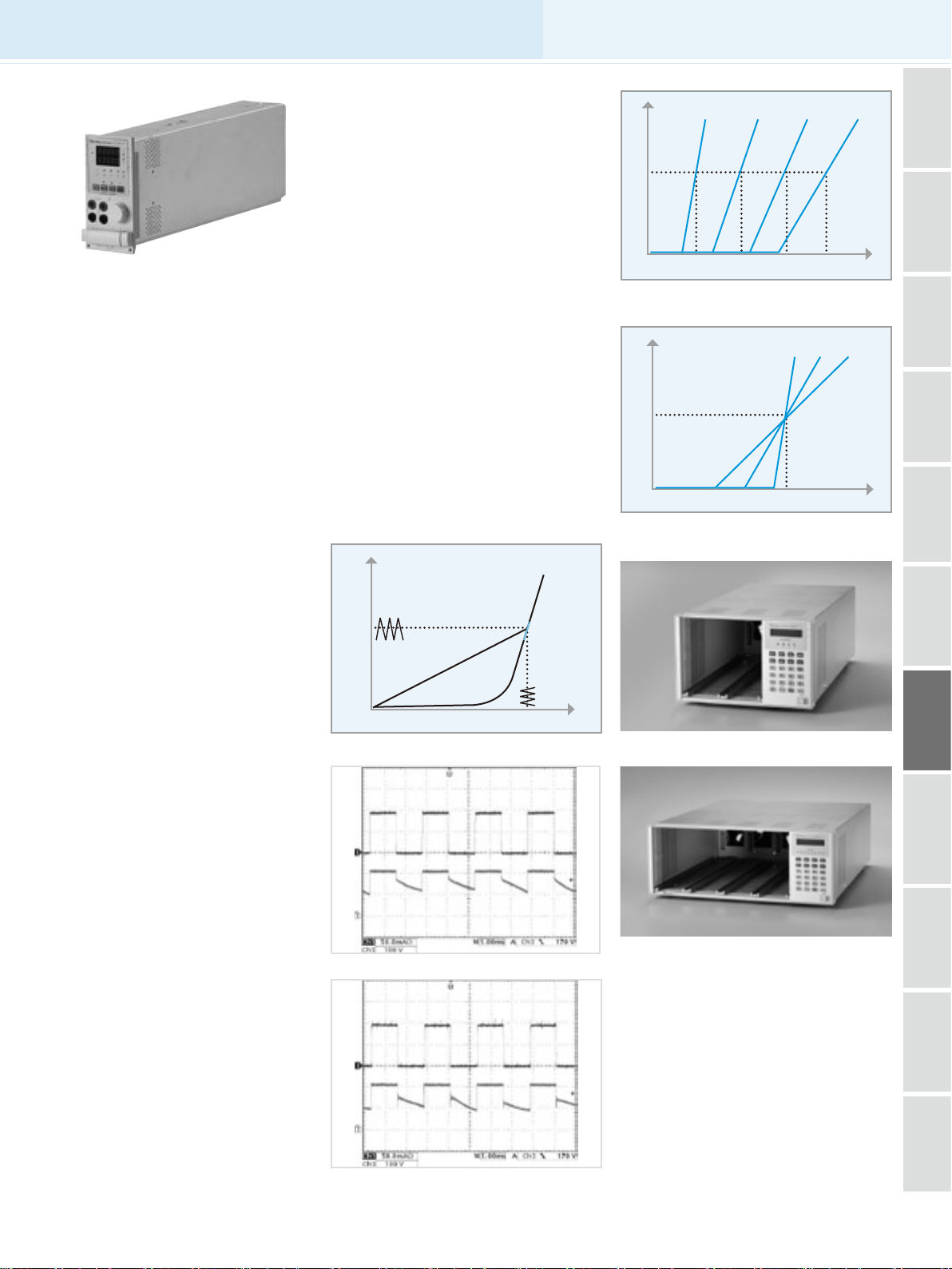
Figure 4 Simulate different number of LEDs
I
Io
Figure 5 Simulate different characteristic of LEDs
d1 Rd2 Rd3 Rd4
V
o1 Vo2 Vo3 Vo4
R
d3 Rd2 Rd1
V
F1 VF2 VF3 Vo
V
V
Test Equipment
Test Equipment
Test Equipment
Test Equipment
Test Equipment
Equipment
Photovoltaic
Semiconductor/IC
LED
LCD/LCM
Video & Color
Optical Inspection
However, all these testing methods, each of them
has their own disadvantages.
As shown on the V-I curve in Figure 1, the LED has
a forward voltage VF and a operating resistance
(Rd). Whe n using a resistor as loa ding, the V-I
curve of the resistor is not able to simulate the V-I
curve of the LED as shown on Figure 1. This may
cause the LED power driver to not start up due
to the difference in V-I characteristic between
the resistors and the LEDs. When using Electronic
Loads, the CR and CV mode settings are set for
wh en the LED is un der sta ble oper ation and
therefore, is unable to simulate turn on or PWM
brightness control characteristics. This may cause
the LED powe r driver to funct ion improper ly
or trigger it's protection circuits. These testing
requirements can be achieved when using a LEDs
as a load; however, issues regarding the LED aging
as well as different LED power drivers may require
different types of LEDs or a number of LEDs. This
makes it inconvenient for mass production testing.
Io
Figure 1 LED V-I Characteristics
Figure 2 LED dimming test
Vo
Rd
V
6312A : 2 in 1 Mainframe
6314A : 4 in 1 Mainframe
Power Electronics
Test Equipment
Passive Component
Test Instruments
Test Instruments
Electrical Safety
Test Instruments
General Purpose
Figure 3 63110A dimming test
• Continued on next page ➟
& Systems
11-12
PXI Instruments
Page 2
11-13
All specifications are subject to change without notice. All specifications are subject to change without notice.
Programmable DC Electronic Load Model 63110A/63113A
SPECIFICATIONS
Model 63110A (100Wx2) 63113A *3
Power 100W 300W
Current 0~0.6A 0~2A 0~5A 0~20A
Voltage *1 0~500V 0~300V
Min. Operating Voltage 6V@2A 4V@20A
LED Mode
Operation Voltage: 0~100V/0~500V
Rd Coefficient : 0.001~1
Range
Resolution *2
Constant Resistance Mode
Range
Resolution*2
Accuracy
Constant Voltage Mode
Range 0~500V 0~300V
Resolution 20mV 6mV
Accuracy 0.05% + 0.1%F.S. 0.05% + 0.1%F.S.
Constant Current Mode
Range 0~0.6A 0~2A 0~5A 0~20A
Resolution 12µA 40µA 100µA 400µA
Accuracy 0.1%+0.1% F.S. 0.1%+0.1% F.S. 0.1%±0.2% F.S.
Measurement Section
Voltage Read Back
Range 0~100V 0~500V 0~60V 0~300V
Resolution 2mV 10mV 1.2mV 6mV
Accuracy 0.025%+0.025% F.S. 0.025%+0.025% F.S.
Current Read Back
Range 0~0.6A 0~2A 0~5A 0~20A
Resolution 12µA 40µA 100µA 400µA
Accuracy 0.05%+0.05% F.S. 0.05%+0.05% F.S.
NOTE*1 : If the operating voltage exceeds 1.1 times of the rated voltage, it would cause permanent damage to the device.
NOTE*2 : S (siemens) is the SI unit of conductance, equal to one reciprocal ohm.
NOTE*3 : Call for availability
VF: 0~100V/0~500V
Current : 0~2A
Rd: 1Ω~1kΩ/10Ω~10kΩ
Vo : 4mV/20mV
Io : 0.1mA
Rd Coefficient : 0.001
Rd : 62.5µs/6.25µs
VF : 4mV/20mV
CRL : 3Ω~1kΩ (100W/100V)
CRH : 10Ω~10kΩ (100W/500V)
CRL : 62.5µS
CRH : 6.25µS
1kΩ : 4mS+0.2%
10kΩ : 1mS+0.1%
Operating Voltage : 0~60V/0~300V
Rd Coefficient : 0.001~1
VF : 0~60V/0~300V
LEDL @ CCH : 0~60V- 0~20A (Rd: 0.05Ω~50Ω)
LEDL @ CCL : 0~60V- 0~5A (Rd: 0.8Ω~800Ω)
LEDH @ CCL : 0~300V- 0~5A (Rd: 4Ω~4kΩ)
Vo : 1.2mV/6mV
Io : 100µA/400µA
Rd Coefficient : 0.001
Rd : 400µs / 25µS / 5µS
VF : 1.2mV/ 6mV
CRL @ CCH : 0.2Ω~200Ω (300W/60V)
CRL @ CCL : 0.8Ω~800Ω (300W/60V)
CRH @ CCL : 4Ω~4kΩ (300W/300V)
CRL @ CCH : 100µS
CRL @ CCL : 25µS
CRH @ CCL : 5µS
200Ω : 0.2% (setting + range)
800Ω : 0.2% (setting + range)
4kΩ : 0.2% (setting + range)
 Loading...