

Page 1
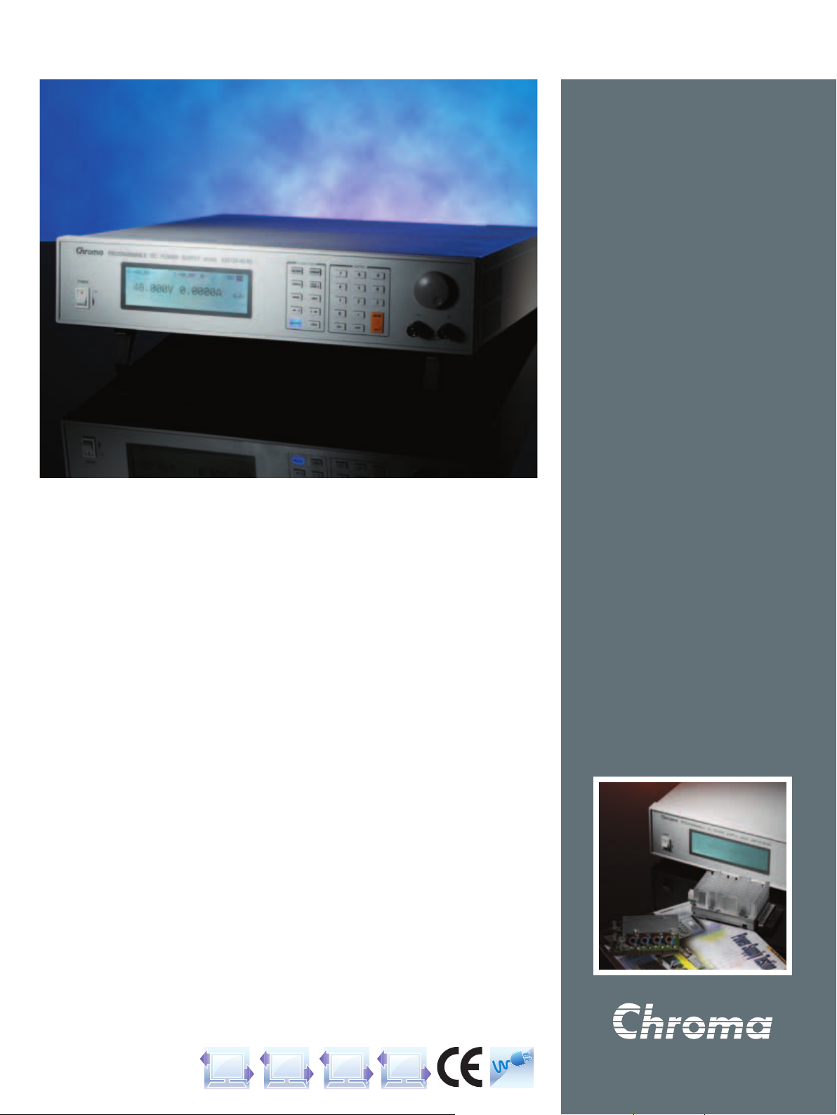
Programmable
DC Power Supply
PROGRAMMABLE DC POWER SUPPLY
MODEL 62000P SERIES
Chroma's new
power supplies offer many unique advantages
for ATE integration and testing. These advantage
include a constant power operating envelope,
precision readback of output current and voltage,
outpu t trig ge r signals as wel l as the ability to
cr eat e co mpl ex DC tr ans ien ts wav eforms to
test device behavior to spikes, drops, and other
vo lta ge devia tio ns.D esi gne d for aut oma ted
testing DC-DC conver ters and similar products,
the
programmable DC supplies.
The
ranging from
to
envelope a single instrument can provide both
high voltage/low current AND low voltage/high
current thereby reducing the number of supplies
needed in typical ATE applications.
P sets a new standard for high accuracy
62000
P Series includes 12 different models
62000
V. Due to their constant power operating
600
P Series of programmable DC
62000
600
W to
5000
W, up to
A and up
120
The
ca pabi lit y for accu rat e vol tag e and curre nt
readi ngs. This mea ns systems no longer nee d
com plex shunt/multiple xers to make accurate
read ings of th e UUT's inp ut par amete rs. The
instruments also include I/O ports providing 8
bit TTLs, DC-ON, fault output signal and remote
inhibit as well as a output trigger signal for system
timing measurements.
Another unique capability of the
supplies is th ei r abi li ty to create complex DC
transient waveforms. This capability allows devices
to be test ed to DC volta ge drop out s, sp ike s
and other voltage vari ations mak ing them an
ideal choice for airborne device testing, inverter
testing and other devices which will experience
voltage interrupts. Applications include DC/DC
Converter & Inver ter voltage drop test, engine
start-up simulation, battery automated charging,
electronic product life cycle test, and etc.
P Series also includes 16 bit readback
62000
62000
P Series
MODEL
62000
P SERIES
Key Features:
Wide range of Voltage & Current
■
Combinations with Constant Power
Voltage range : 0 ~
■
Current range : 0 ~
Power Range :
Digital Encoder Knobs, Keypad
■
and Function Keys
Power Factor Correction (0.95)
■
High-speed Programming
■
Precision V&I Measurements
■
Current Sharing for Parallel Operation
■
with Master/Slave Control
Voltage Ramp Function : Time Range
■
(10ms~99hours)
Auto Sequencing Programming : 10
■
Programs /
Voltage & Current Slew Rate Control
■
OVP, Current Limit, Thermal Protection
■
Remote sense, 5V Line Loss Compensation
■
APG (Analog Programmable Interface)
■
with Isolated Analog Interface Card
Optional GPIB Control with SCPI
■
Optional Ethernet/LXI interface
■
Standard RS-
■
LabView and Labwindows
■
CE Certified
■
600
100
232
V
600
A
120
W,
W,
2400
W,
1200
Sequences / 8 bit TTL
& USB Interface
5000
W
GPIBRS-232USB
Ethernet
PFC
Page 2
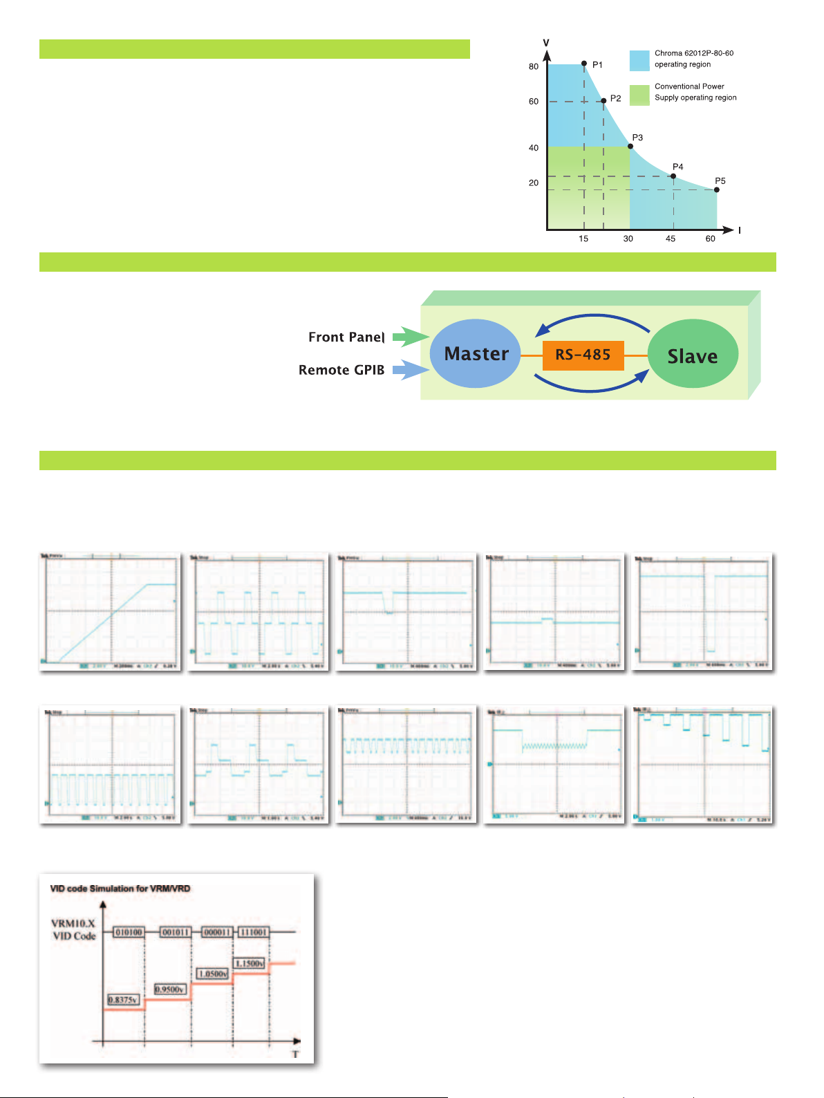
WIDE OPERATING REGION WITH CONSTANT POWER
Th e
specificati on for model
various combinations as shown in the figure at the right. As shown conventional power
supplies prov ide the same rated cu rr ent at all output voltages, howe ver, the
provides greater current at lower outpu t voltage s. This means both low voltage/high
current and high voltage/low current UUTs can be tested using a single supply avoiding the
for multiple supplies saving cost and space within typical ATE systems.
P Serie s suppl ies offe r a wide op erating re gion. For exam ple, the outpu t
62000
62012P-80-60
is
1200W/80V/60
A, it allows operating flexibly in
62000
MASTER/SLAVE PARALLEL & SERIAL CONTROL
Wh en high power is requ ired, it is comm on to
connect two or more power supplies in parall el
or series. Th e
sm a rt Ma s te r / S l av e co nt ro l m o de mak in g
s e ri e s / p ar al le l o pe ra ti o n f as t a nd s
I n th i s mo d e the mas te r sc a le s va l ue s a n d
downl oa ds data to slave units so programming
i s s im p le an d c ur re nt s ha r i ng a ut om at i c .
P S er ies s upplies have a
62 000
i m pl e.
PROGRAMMING SEQUENCES APPLICATIONS
P
The
cu rre nt slew rate con tro l and 8 bit T TL outpu t fo r aut oma ted test app lic ati ons. Ap pli cat ion s inc lud e DC/D C Co nve rte r & In ver ter volt age
opout t e s t i n g, engine s t a r t-u p si mu la tion, batter y au to m ated c h a rging, pr od uc t li fe cy cl e te sting an d ai rb or n e av io n i c s te st i n g.
dr
Soft Start Testing Voltage Step Waveform D/D Converter Sag Testing D/D Converter Surge Testing D/D Converter Cycle drop Testing
Pulse Charge of Battery Life Cycle Testing Line Regulation Testing Starting Profile of ISO
P S er i es su pp li es al lo w fo r
62 000
us er pro gr am ma bl e se qu en ces wi th ti me setting s ra ng in g fr om 5ms t o
10 0
16750-2
Th e
output TTL bits with timing control.
These control lines can be used for
VID cont rol of VRM or to control
other discrete signals.
P Su ppli es pro vid e 8
62000
s, vo lt ag e /
15 000
Reset Behavior at Voltage
Drop of ISO
16750-2
Page 3

PANEL DESCRIPTION
Model : 62012P-80-60
1 2 3 7654
8 9 10
1. LCD Display
2. PROG Key
3. CONFIG Key
4. VOLTAGE Key
5. CURRENT Key
6. NUMERIC Key
7. ROTARY Key
8. POWER Switch
9. OUTPUT Key
10. LOCK Key
11. OUTPUT
Note : 40V,
Display setting, readings and operating status
Program the sequence
Set the system configuration
Set the output voltage
Set the output current limit
Set the data
Adjust the V&I and set the parameter
Enable or disable the output
Lock all settings
Terminal
V &
300
V Model have no output terminal at the front panel.
600
Connect the output cable to a UUT
11
Model : 62012P-80-60
12 19181716151413 20
12. OUTPUT Terminal
13. Sense Terminal
14. System Fan
15. Analog programming interface
16. System I/O port
and trigger input signal
17. GPIB Connector(Optional)
18. RS-232 Connector
19. RS-485 Connector
20. AC Input Terminal
21. USB Connector
Connect the output cable to a UUT
Connect the UUT for voltage compensation
For analog level to program and monitor output voltage & current
Send 8 bit TTL, DC-ON, fault output signal and remote inhibit
GPIB & Ethernet (alternative)
For master/slave control
21
Page 4

SPECIFICATIONS -1
Model 62006P-30-80 62006P-100-25 62006P-300-8 62012P-40-120 62012P-80-60 62012P-100-50
Output Ratings
Output Voltage
Output Current
Output Power
Line Regulation
Voltage
Current
Load Regulation
Voltage
Current
Voltage Measurement
Range
Accuracy
Current Measurement
Range
Accuracy
Output Noise (0 ~ 20MHz)
Voltage Ripple (P-P)
Voltage Ripple (rms)
Current Ripple (rms)
OVP Adjustment Range
Slew Rate Range
Voltage (with USB)
Current (with USB)
Programming Response Time (Typical)
Rise Time (Full & No Load)
Fall Time
Eciency
Drift (8 hours)
Voltage
Current
Temperature Coecient
Voltage
Current
Transient Response Time
% step change
10
Voltage limit @ Series Mode
AC Input Voltage Ranges
Operating Temperature
Dimension (H x W x D)
Weight
All specications are subject to change without notice. Please visit our website for the most up to date specications.
0.05
0.1
110
110
0.001
0.001
0.02
0.02
0.04
12
V
0~30
A
0~80
W
600
mV
0.01%+2
0.01%+25
0.0
0.01%+10
350
0.04
95
mA
mV
1%+3
mA
V
6V/30
% + 0.05%F.S.0.05% + 0.05%F.S.0.05% + 0.05%F.S.0.05% + 0.05%F.S.0.05% + 0.05%F.S.0.05% + 0.05%F.S.
A
16A/80
% + 0.2%F.S.
mV
60
mV
8
mA
60
% of Vset to
% of Vmax
V - 5V/ms
A - 1A/ms
ms
6
ms(max)
0.75 0.75 0.75 0.8 0.8 0.8
% of Vmax
% of Imax
% of Vmax/
% of Imax/
mS
3
mV
150
V
150
to
Vac
250
0~40
℃
kg / 26.43 lbs
0.01%+10
0
110
110
0.001
0.001
0.02
0.04
0.02
℃
0.04
℃
12.1
V
0~100
A
0~25
W
600
mV
0.01%+6
mA
0.01%+5
mV
mA
0.01%+5
V
20V/100
A
5A/25
.1% + 0.2%F.S.
mV
85
mV
10
mA
10
% of Vset to
% of Vmax
V - 10V/ms
A - 1A/ms
ms
10
ms(max)
300
% of Vmax
% of Imax
% of Vmax/
% of Imax/
mS
3
mV
180
V
500
to
95
Vac
250
0~40
℃
kg / 26.65 lbs11.2 kg / 24.67 lbs
0.01%+18
0.03%+20
0.01%+50
0.03%+40
0.1
110
110
0.01
0.001
0.02
0.04
0.02
℃
0.04
℃
x
89
430
0~300
A
0~8
W
600
60V/300
1.6A/8
% + 0.1%F.S.
mV
180
mV
90
mA
60
% of Vset to
% of Vmax
V - 10V/ms
A - 1A/ms
ms
30
s(max)
2.5
% of Vmax
% of Imax
% of Vmax/
% of Imax/
mS
3
mV
600
V
800
to
95
250
0~40
℃
x
425
V
mV
mA
mV
mA
V
A
Vac
mm / 3.5
0.01%+2
0.01%+25
0.01%+3
0.01%+10
24
% + 0.1%F.S..
0.1
110
110
0.001
0.001
4
60
0.02
0.04
% of Vmax/
0.02
℃
0.04
℃
95
x 16.93 x 16.73 inch
kg / 26.43 lbs
12
V
0~40
A
0~120
W
1200
mV
mA
mV
mA
V
8V/40
A /
A
120
mV
90
mV
10
mA
120
% of Vset to
% of Vmax
V - 5V/ms
A - 1A/ms
ms
8
ms(max)
% of Vmax
% of Imax
% of Imax/
mS
3
mV
150
V
200
to
Vac
250
0~40
℃
V
0~80
A
0~60
W
1200
mV
0.01%+8
0.01%+10
0.01%+12
0.01%+20
0.1
110
110
0.001
0.001
240
0.02
0.04
0.02
℃
0.04
℃
95
13
mA
mV
mA
V
16V/80
A
12A/60
% + 0.1%F.S.
mV
100
mV
10
mA
30
% of Vset t
% of Vmax
V - 10V/ms
A - 1A/ms
ms
8
ms(max)
% of Vmax
% of Imax
% of Vmax/
% of Imax/
mS
3
mV
250
V
400
to
Vac
250
0~40
℃
kg / 28.63 lbs
o
℃
℃
0~100
0~50
1200
0.01%+10
0.01%+12
0.01%+18
0.01%+28
20V/100
10A/50
% + 0.1%F.S.
0.1
100
15
20
% of Vset
110
to
% of Vmax
110
V - 10V/ms
0.001
A - 1A/ms
0.001
10
ms(max)
300
% of Vmax
0.02
% of Imax
0.04
% of Vmax/
0.02
% of Imax/
0.04
3
250
500
to
95
0~40
kg / 26.65 lbs
12.1
A
W
mV
mV
mA
ms
mS
mV
V
250
℃
V
mV
mA
mV
mA
V
A
Vac
℃
℃
SOFTPANEL
ISO
16750-2 4.5.1
Supply Voltage
Momentary Drop In
ISO
16750-2 4.5.3
Starting Profile
62050P-100-100
Page 5

SPECIFICATIONS -2
Model 62012P-600-8 62024P-40-120 62024P-80-60 62024P-100-50 62024P-600-8 62050P-100-100
Output Ratings
Output Voltage
Output Current
Output Power
Line Regulation
Voltage
Current
Load Regulation
Voltage
Current
Voltage Measurement
Range
Accuracy
Current Measurement
Range
Accuracy
Output Noise (0 ~ 20MHz)
Voltage Ripple (P-P)
Voltage Ripple (rms)
Current Ripple (rms)
OVP Adjustment Range
Slew Rate Range
Voltage (with USB)
Current (with USB)
Programming Response Time (Typical)
Rise Time (Full & No Load)
Fall Time
Eciency
Drift (8 hours)
Voltage
Current
Temperature Coecient
Voltage
Current
Transient Response Time
% step change
10
Vo lt ag e li mi t @ Se ri es
Mode
AC Input Voltage Ranges
Operating Temperature
Dimensions (H x W x D)
Weight
All specications are subject
Note *1 : The max. power limit of
0.01%+18
0.03%+20
0.01%+50
0.03%+40
0.05%+0.05
0.1%+0.1
to
0.01
0.001
0.02
0.04
0.04
11.2
to change without notice. Please visit our website for the most up to date specications.
V
0~600
A
0~8
W
1200
120V/600
1.6A/8
%F.S.0.1%+0.1%F.S.
mV
180
mV
90
mA
60
% of Vset
110
% of Vmax
110
V - 10V/ms0.
A - 1A/ms0.
ms
60
s(max)
5
0.8 0.85 0.85 0.85 0.85 0.85
% of Vmax0.02% of Vmax0.02% of Vmax
% of Imax
% of
0.02
Vmax/
℃
% of Imax/
mS
3
mV
600
V
800
to
95
250
0~40
℃
kg / 24.67lbs13 kg / 28.63 lbs12.2 kg / 26.87 lbs13 kg / 28.63 lbs13 kg / 28.63 lbs
W is under output voltage 22V~40V, and see the diagram below for operating power envelope.
2400
1200~2400W*1 2400
mV 0.01%+2mV
mA 0.01%+25mA
mV 0.01%+3mV
mA 0.01%+10mA
V
%F.S.0.05%+0.05%F.S.0.05%+0.05%F.S.0.05%+0.05%F.S.0.05%+0.05%F.S.
A
to
0.04
0.04
℃
190
Vac
(single phase)
V
0~40
0~120A*1 0~60
0.01%+8
0.01%+10
0.01%+12
0.01%+20
V / 40V
8
A /
120
24
mV
90
mV
10
mA
120
% of Vset
110
% of Vmax
110
V - 5V/ms0.
001
A - 1A/ms0.
001
ms
8
ms(max)
460
% of Imax
% of
0.02
Vmax/
% of Imax/
mS
3
mV
150
V
200
to
250
0~40
℃
x
89
A
℃
Vac
430
16V/80
12A/60
0.1%+0.1
100
110
o
t
110
001
001
240
0.04
% of Vmax/
0.02
% of Imax/
0.04
℃
250
to
190
(single phase)
0~40
x
mm / 3.5 x 16.93 x 16.73 inch
425
V
0~80
A
W
mV
mA
mV
mA
V
A
%F.S.
mV
mV
10
mA
30
% of Vset
% of Vmax
V - 10V/ms0.
A - 1A/ms0.
ms
8
ms(max)
% of Imax
℃
℃
mS
3
mV
V
400
Vac
250
℃
V
0~100
A
0~50
W
2400
0.01%+10
0.01%+12
0.01%+18
0.01%+28
0.1%+0.1
110
to
110
001
001
300
0.02
0.04
0.02
0.04
190
(single phase)
mV
0.01%+18
mA
0.03
mV
0.01%+50
mA
0.03%+40
V
20V/100
A
10A/50
%F.S.0.1%+0.1%F.S.
mV
100
mV
15
mA
20
% of Vset
% of Vmax
V - 10V/ms0.01V - 10V/ms
A - 1A/ms0.
ms
10
ms(max)
% of Vmax0.02% of Vmax
% of Imax
% of Vmax/
% of Imax/
mS
3
mV
250
V
500
to
250
0~40
℃
Vac
℃
℃
110
to
0.04
0.04
190
(single pha
0~600
0~8
2400
+20mA
%
V /
120
A / 8A
1.6
mV
180
mV
90
mA
60
% of Vset
% of Vmax
110
A - 1A/ms
001
ms
60
s(max)
5
% of Imax
% of
0.02
Vmax
% of Imax/
mS
3
mV
600
800
to
250
0~40
V
A
W
mV
mV
mA
V
600
/
℃
℃
V
(3 phase 4 wire, Delta connection)
Vac
se)
(3phase 5 wire, Y connection)
℃
176
6.93
V
0~100
A
0~100
W
5000
mV
0.01%+8
0.01%+24
0.01%+12
0.01%+56
0.05%+0.05
0.1%+0.1
110
to
0.001
0.001
850
0.02
0.04
0.02
0.04
190
or
x
x 16.85 x 22.28 inch
28
mA
mV
mA
V
20V/100
%F.S.
A
20A/100
%F.S.
mV
50
mV
15
mA
40
% of Vset
% of Vmax
110
V - 10V/ms
A - 2A/ms
ms
10
ms(max)
% of Vmax
% of Imax
% of Vmax/
% of Imax/
mS
3
mV
250
V
500
to
Vac
250
to
0~40
Vac
440
℃
x
mm /
566
342
428
kg / 61.67 lbs
℃
℃
ORDERING INFORMATION
62006P-30-80:
62006P-100-25:
62006P-300-8:
62012P-40-120
62012P-80-60:
62012P-100-50:
62012P-600-8:
62024P-40-120:
62024P-80-60:
62024P-100-50:
62024P-600-8:
62050P-100-100:
A620004:
A620006:
A620009:
A620015:
A620023:
Programmable DC Power Supply, 30V/80A/
Programmable DC Power Supply,
Programmable DC Power Supply,
Programmable DC Power Supply, 40V/
:
Programmable DC Power Supply, 80V/60A/
Programmable DC Power Supply,
Programmable DC Power Supply,
Programmable DC Power Supply, 40V/
Programmable DC Power Supply, 80V/60A/
Programmable DC Power Supply,
Programmable DC Power Supply,
Programmable DC Power Supply,
GPIB Interface for Model
Rack mounting kit for Model
Softpanel for
Rack mounting kit for Model
Ethernet/LXI Interface for Model
62000
P Series
P Series
62000
62000
62050P-100-100
62000
W
600
100V/25A/600
300V/8A/600
100V/50A/1200
600V/8A/1200
100V/50A/2400
600V/8A/2400
100V/100A/5000
P Series (2U model)
P Series
W
120A/1200
1200
120A/2400
2400
W
W
W
W
W
W
W
W
W
W
Model 62024P-40-120
The green area is over specification due to
low voltage (<22V) & high current output (>
The following is operation power envelope :
(10V/
(20V/
120
110
A), (11V/
A), (22V/
A), (15V/
110
A), (24V/
109
(30V/80A), (40V/60A).
110
110
100
A).
A),
A),
Page 6

GENERAL SPECIFICATIONS
Programming & Measurement Resolution
Voltage (Front Panel)
Current (Front Panel)
Voltage (Remote Interface)
Current (Remote Interface)
Voltage (Analog Programming Interface )
Current (Analog Programming Interface )
Programming Accuracy
Voltage Programming (Front Panel and Remote Interface )
Voltage Programming (Analog Programm
ing Interface )
Current Programming (Front Panel and Remote Interface )
Current Programming (Analog Programming Interface )
Programming Response Time
Rise Time : For a programmed 5% to 95% step in output voltage.(Full & No Load)
Fall Time : For a programmed 95% to 5% step in output voltage.
(The fall time will be aected by the external
loading from UUT.)
Vout setting (USB send command to DC source receiver)
Measure Volt , Current (under USB command using Fetch)
Measure Volt , Current (under USB command using Measure)
Analog Programming Interface
Voltage and Current Programming inputs
Voltage and Current monitor
Isolation : Maximum working voltage of any analog progr
amming signal with respect to chassis potential.
Auxiliary Power Supply
Output Voltage
Maximum Current Source Capability
Remote inhibit function (I/O)
Use to disable the output of DC power supply; Active Low TTL
DC-ON Output Signal
Indicate the output status; Active High TTL
Fault output signal
Indicate if there is a fault/protection occurred; Active Low TTL
Series & Parallel operation function
with Master / Slave control
Voltage limit @ Series Mode See Electrical Specication
Number of DC Power Supplies allowed @ Master / Slave control mode
Auto Sequencing Programmable Function
Number of program
Number of sequence
Time Range
TTL signal out
TTL source capability
Voltage Step Mode Programmable Function
Start Voltage Range
End Voltage Range
Total R
un Time Range (hhh:mm:ss.sss)
Slew Rate Control Function
Voltage slew rate range
(The fall slew rate will be aected by the discharge rate of the output capacitors especially under no load condition.)
Current slew rate range See Electrical Specication
Minimum transition time.
Remote Sense
Line loss compensation
All specications are subject to change without notice. Please visit our website for the most up to date specications.
mV
10
mA
10
% of Vmax
0.003
% of Imax
0.002
% of Vmax
0.04
% of Imax
0.04
% of Vmax
0.1
% of Vmax
0.2
% of Imax
0.3
% of Imax
0.3
See Electrical Specication
ms
10
ms
10
ms
70
Vdc or 0~5Vdc of F.S.
0~10
Vdc or 0~5Vdc of F.S.
0~10
Vdc
70
Vdc
12
mA
10
5
10
100
ms - 15,
5
bits
8
mA
7
~full scale
0
~full scale
0
ms - 99 hours
10
000
S
See Electrical Specication
ms
0.5
V
5
Developed and Manufactured by :
CHROMA ATE INC.
致茂電子股份有限公司
HEADQUARTERS
Hwaya 1st Rd., Kueishan
66
Hwaya Technology Park,
Taoyuan County
Taiwan
Tel: +
Fax: +
http://www.
E-mail: info@chromaate.com
33383
886-3-327-9999
886-3-327-8898
chromaate.com
CHINA
CHROMA ELECTRONICS
(SHENZHEN) CO., LTD.
F, No.4, Nanyou Tian An
8
Industrial Estate, Shenzhen,
,
China PC:
Tel: +86Fax: +86-
518052
755-2664-4598
755-2641-9620
JAPAN
CHROMA JAPAN CORP.
Nippa-cho, Kouhoku-ku,
472
Yokohama-shi, Kanagawa,
Japan
223-0057
http://www.chroma.co.jp
E-mail: info@chromaate.com
U.S.A.
CHROMA SYSTEMS
SOLUTIONS, INC.
Commercentre Drive,
25612
Lake Forest, CA
Tel: +1Fax: +1Toll Free: +1http://www.chromausa.com
E-mail: sales@chromausa.com
92630-8830
949-600-6400
949-600-6401
866-600-6050
EUROPE
CHROMA ATE EUROPE B.V.
Morsestraat 32,
The Netherlands
Tel: +31-
318-648282
Fax: +31-
318-648288
http://www.chromaeu.com
E-mail: sales@chromaeu.com
6716
AH Ede,
Worldwide Distribution
and Service Network
P-E-
62000
201207-2000
 Loading...