

Page 1
PROGRAMMABLE DC POWER SUPPLY
MODEL 62000H SERIES
Chroma's new 62000H Series of programmable
D C p o w e r su p p l i e s of f e r ma ny un iq u e
adv anta ges for te lec om, a uto m ate d te s t
sys t em & i n teg r ati o n, i n dus t ria l, ba tte r y
charge & simulation for hybrid cars and solar
panel simulation. These advantages include
high power density of 15KW in 3U, precision
readback of output current and voltage, output
trigger signals as well as the ability to create
complex DC transient waveforms to test device
behavior for spikes, drops, and other voltage
deviations.
The 62000H Se rie s in clu des 14 diff ere nt
mod els ran gin g fr om 5KW to 15KW, w ith
current range up to 375A and voltage range
up to 1000V. The 62000H can easily parallel
up to ten uni t s ca p a b l e of 15 0KW wi t h
current sharing for bulk power app lications,
for examp l e, batte r y ban k s imul a tio n o f
450V/150A/67.5KW for ele ct ri c veh ic le and
military use.
The re ar e 100 u ser p r ogr amma ble i n put
status on the front panel for automated test
ap pl ication and lif e c yc le ON/OFF tes t. In
addition, the 62000H has a 16 bit digital control
with bright vacuum fluorescent display readout.
The 62000H series DC power supplies ar e
very easy to operate either from the front panel
keypad or from the remote controller via USB
/ RS232 / RS485 / APG (Standard) and GPIB
& Ethernet (optional). Its compact size with 3U
only can be stacked on a bench in a standard
rack without any difficulty.
An oth er uni qu e capa bilit y of the 62000H
supplies is their ability to create complex DC
transient wavef orms. This capabi lity allows
devices to be tested to DC voltage dropouts,
spikes and other voltage vari ations making
them an id eal ch oice for aerosp ace device
testing, inverter testing and other devices which
will experience voltage interrupts. Applications
include DC/DC co nverter & inverte r voltage
drop test, engine start-up simulation, battery
autom ated charging, elec tronic prod uct life
cycle test, etc.
Programmable
DC Power Supply
MODEL 62000H SERIES
Key Features :
■ Power range: 5KW / 10KW / 15KW
■ Voltage range: 0 ~ 1000V
■ Current range: 0 ~ 375A
■ High power density (15KW in 3U)
■ Easy master / slave parallel & series
operation up to 150KW
■ Precision V&I Measurements
■ High-speed programming
■ Voltage & Current slew rate control
■ Digital encoder knobs, keypad and
function keys
■ Current sharing operation
■ Voltage ramp function
(time range: 10 ms ~ 99 hours)
■ Auto sequencing programming:
10 programs / 100 sequences
■ OVP, current limit, thermal protection
■ Standard analog programming interface
■ Standard USB / RS232 / RS485 interface
■ Optional GPIB / Ethernet interface
■ Remote output ON / OFF (I / P)
■ Remote sense line drop compensation
■ LabView and Labwindows
■ Solar array simulation function
■ Shade I-V curve simulation
■ I-V curve programming:
10 program / 100 I-V files
■ CE certified
Ethernet
GPIBRS-485APG RS-232
USB
Page 2
HIGH POWER DENSITY 15KW IN 3U PROGRAMMABLE DC POWER SUPPLY
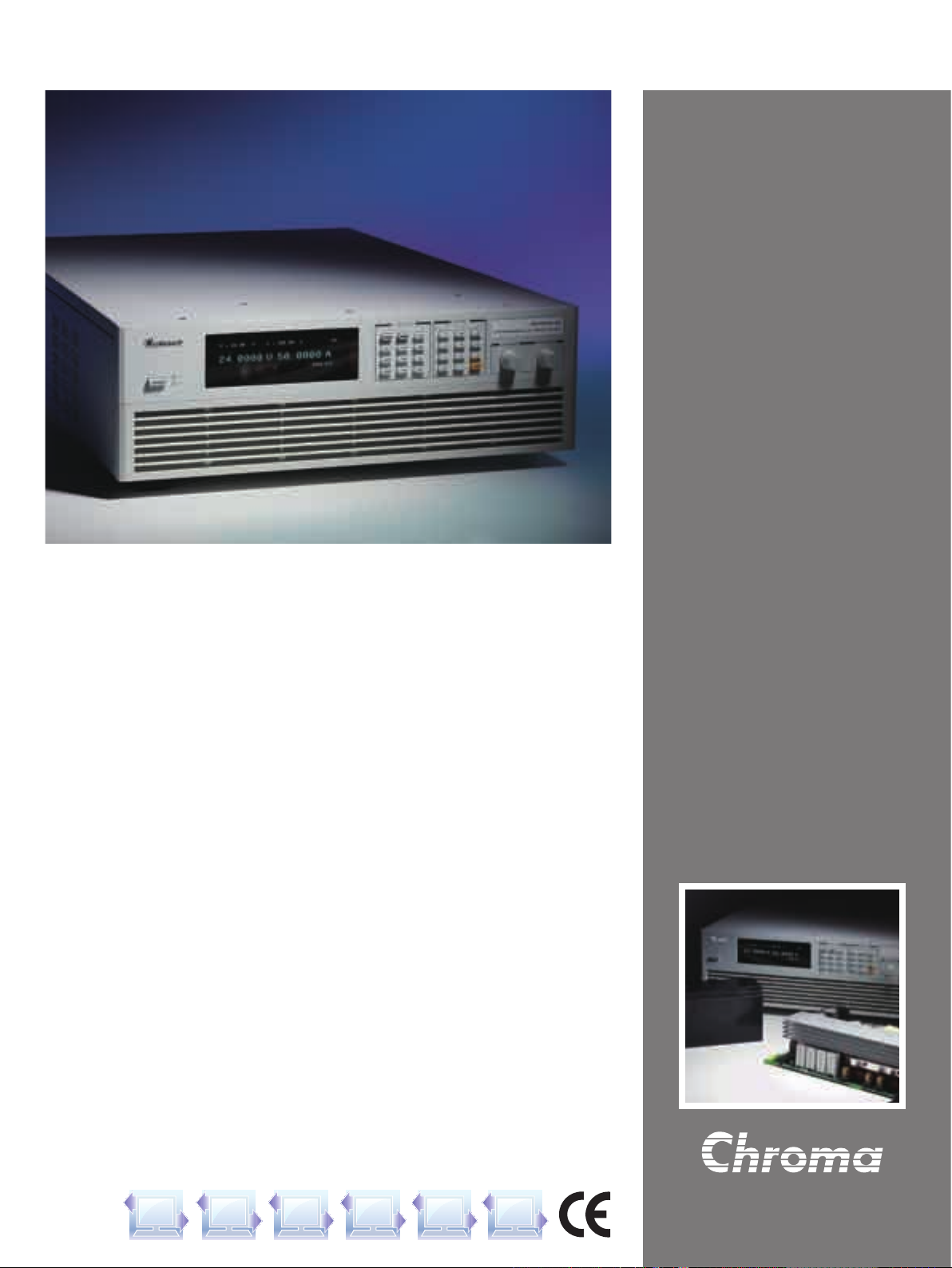
Th e 62000H S eries suppl ies offer a hi gh
power density envelop of maximum 15KW
in 3U, deliv er low output noise and ripple,
exc ell ent line and load regulation, and fast
tra n s ien t r e spon s e, with wi d e ra n g e of
vo ltage (30V~1000V), curr en t (375A~25A)
com bin ati ons , suit a ble for e ver y pa rt of
your manufacturing process from de sign to
production testing.
3U
(132.8mm)
MASTER / SLAVE PARALLEL & SERIES OPERATION UP TO 150KW
When high power is required, it is common to connect two or more power supplies in parallel or series. The 62000H Series supplies have a
smart Master / Slave control mode making series/parallel operation fast and simple. In this mode, the master scales values and downloads
data to slave units so programming is simple and current sharing automatic.
Local Front Panel
Master Slave
Remote GPIB/USB/RS232
SYSTEM
BUS
RS485/Ethernet
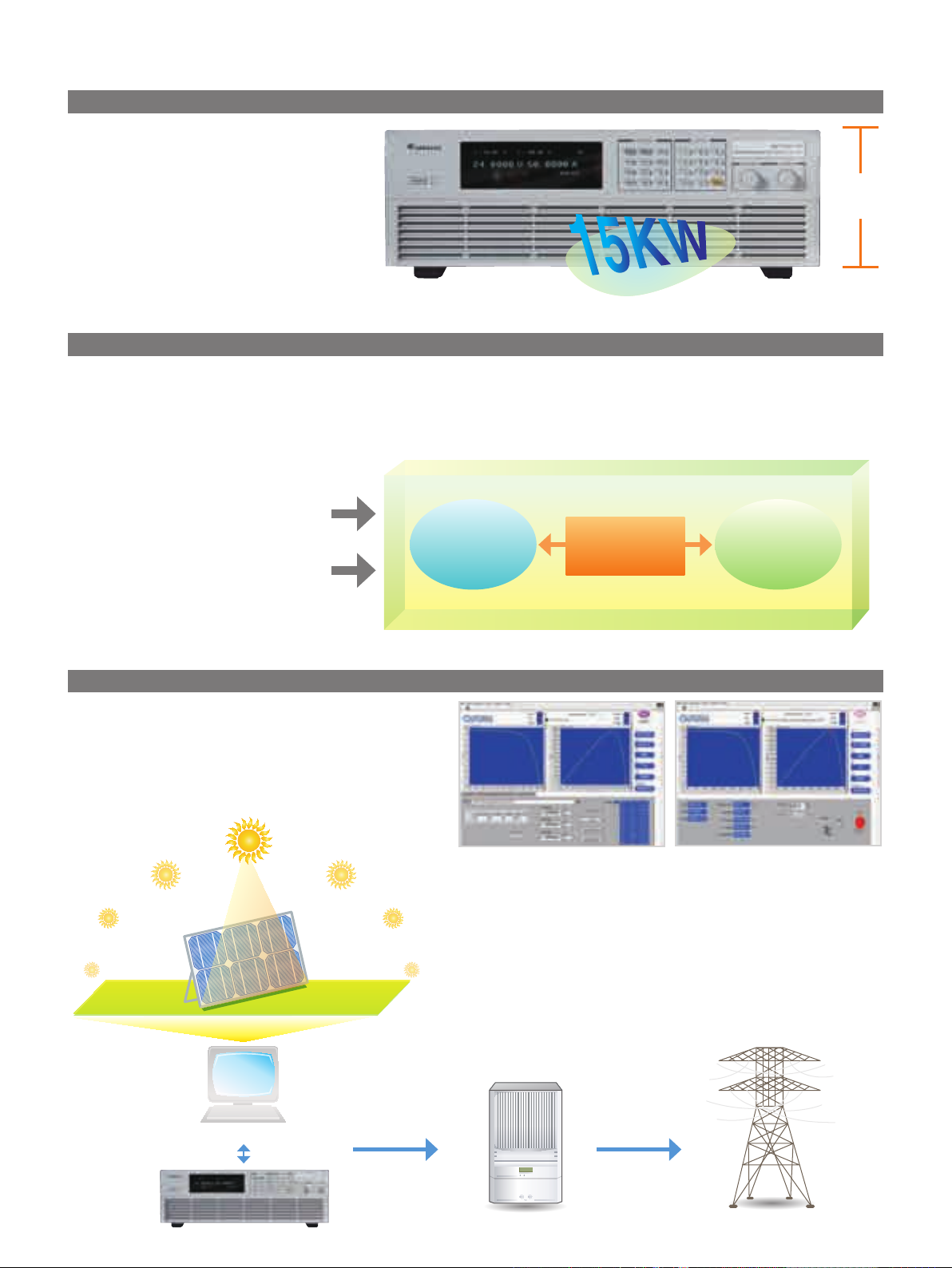
SOLAR ARRAY SIMULATION FUNCTION *
Mo del 62150H-600S/1000S pr ovi de s a u niq ue f eat ure to
simulate the output characteristics of a solar array. This function
is useful for MPPT performance evaluation on solar inverter
device. User can easily edit the I-V curve, testing and monitor
the PV inverter via softpanel , see the right Figure A & B.
*Call for availability
Solar Panel
Figure A : IV Curve Edit Table Mode
Figure B : Static MPPT Test
PC
Solar Array Simulator
DC Voltage Input AC Power Output
UUT (Solar Inverter)
Page 3
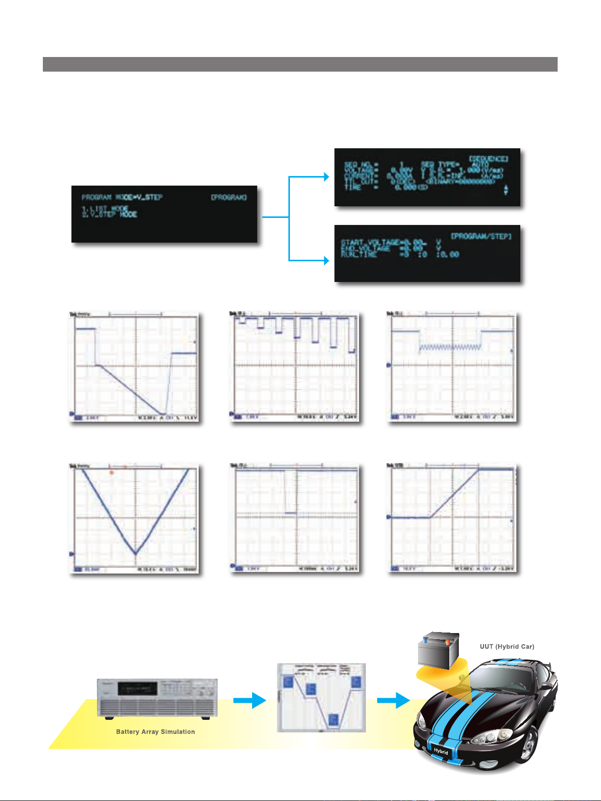
PROGRAMMING SEQUENCES APPLICATIONS
The 62000H Series supplies' LIST and STEP modes allow for auto sequencing function. The LIST mode allows for 100 user programmable
sequences with time settings ranging from 5ms to 15000s and voltage / current slew rate control. The STEP mode allows for setting start, end
voltage and run time of 10ms to 99 hours for automated test applications. Applications include DC/DC Converter & Inverter voltage dropout
testing, engine start-up simulation, battery automated charging, battery voltage dropout simulation, product life cycle testing and avionics
testing.
LIST Mode
STEP Mode
Battery Voltage Dropout
Battery Voltage Slow
Decrease & Decrease profile
Reset Behavior at Voltage Drop
of ISO 16750-2
Telecom Converter Sag Testing Output Voltage Slew Rate Control
Engine Starting Profile
of ISO 16750-2
Page 4

PANEL DESCRIPTION
1 2 3 4 5 6 7 8 9 10
1. POWER Switch
2. VFD Display
Display setting, readings and operating status
3. LOCK Key
Lock all settings
4. OUTPUT Key
Enable or disable the output
5. CONFIG Key
Set the system configuration
6. VOLTAGE Key
Set the output voltage
7. CURRENT Key
Set the output current
8. PROG Key
Program the sequence
9. NUMERIC Key
Set the data
10. ROTARY Key
Adjust the V&I and set the parameter
11 12 13 14 15 16 17 18 19 20
11. Analog programming interface
For analog level to program and monitor output
voltage & current
12. RS-232 or RS-485 Interface (alternative)
13. System Bus
For master/slave parallel and series control
14. USB Interface
15. OUTPUT Terminal
Connect the output cable to a UUT
16. System Fan
With fan speed control
17. Current Sharing Terminal
Connect the cable to slave unit
18. Sense Terminal
Connect the UUT for voltage compensation
19. GPIB or ETHERNET Interface (optional)
20. AC Input Terminal
ORDERING INFORMATION
Power Rating 62000H Series Programmable DC Power Supply
62050H-40 : Programmable DC Power Supply 40V/125A/5KW
5KW
10KW
15KW
Options
Note :
Please specify the input voltage level at time of order.
GPIB or Ethernet Interface (alternative). Please specified at time of order.
*Call for Availability.
*62050H-450 : Programmable DC Power Supply 450V/11.5A/5KW
62050H-600 : Programmable DC Power Supply 600V/8.5A/5KW
62075H-30 : Programmable DC Power Supply 30V/250A/7.5KW
62100H-30 : Programmable DC Power Supply 30V/375A/11KW
62100H-40 : Programmable DC Power Supply 40V/250A/10KW
*62100H-450 : Programmable DC Power Supply 450V/23A/10KW
62100H-600 : Programmable DC Power Supply 600V/17A/10KW
*62100H-600S: Programmable DC Power Supply 600V/17A/10KW with Solar Array Simulation
62150H-40 : Programmable DC Power Supply 40V/375A/15KW
62150H-450 : Programmable DC Power Supply 450V/34A/15KW
62150H-600 : Programmable DC Power Supply 600V/25A/15KW
62150H-600S : Programmable DC Power Supply 600V/25A/15KW with Solar Array Simulation
*62150H-1000S:Programmable DC Power Supply 1000V/15A/15KW with Solar Array Simulation
GPIB Interface for 62000H Series (Factory installed)
Ethernet Interface for 62000H Series (Factory installed)
Rack Mounting Kit for 62000H Series
Page 5

ELECTRICAL SPECIFICATIONS -1
Model 62075H-30 62050H-40 62050H-450 62050H-600 62100H-30 62100H-40
Output Ratings
Output Voltage 0-30V 0-40V 0-450V 0-600V 0-30V 0-40V
Output Current 0-250A 0-125A 0-11.5A 0-8.5A 0-375A 0-250A
Output Power 7500W 5000W 5000W 5000W 11250W 10000W
Line Regulation
Voltage ±0.01% F.S.
Current ±0.05% F.S.
Load Regulation
Voltage ±0.02% F.S.
Current ±0.1% F.S.
Voltage Measurement
Range 6V / 30V 8V / 40V 90V / 450V 120V / 600V 6V / 30V 8V / 40V
Accuracy 0.05% + 0.05% F.S.
Current Measurement
Range 50A / 250A 25A / 125A 2.3A / 11.5A 1.7A / 8.5A 75A / 375A 50A / 250A
Accuracy 0.1% + 0.1% F.S.
Output Noise & Ripple
Voltage Noise (P-P) 60mV 60mV 300mV 350mV 60mV 60mV
Voltage Ripple (rms) 15mV 15mV 450mV 600mV 15mV 15mV
Current Ripple (rms) 100mA 50mA 20mA 15mA 150mA 100mA
OVP Adjustment Range
Range 0-110% programmable from front panel or digital
Accuracy ±1% of full-scale output
Programming Response Time
Rise Time: Full Load 6ms 8ms 60ms 60ms 6ms 8ms
Rise Time: No Load 6ms 8ms 60ms 60ms 6ms 8ms
Fall Time: Full Load 6ms 8ms 60ms 60ms 6ms 8ms
Fall Time: 10% Load 100ms 100ms 250ms 250ms 100ms 100ms
Fall Time: No Load 1s 1s 2.5s 2.5s 1s 1s
Slew Rate Control
Voltage slew rate
range
Current slew rate
range
Minimum transition
time
Transient Response
Time
Efficiency 0.87(Typical)
Drift (30 minutes)
Voltage 0.04% of Vmax
Current 0.06% of Imax
Drift (8 hours)
Voltage 0.02% of Vmax
Current 0.04% of Imax
Temperature Coefficient
Voltage 0.04% of Vmax/°C
Current 0.06% of Imax/°C
All specifications are subject to change without notice. Please visit our website for the most up to date specifications.
0.001V/ms - 5V/ms 0.001V/ms - 5V/ms 0.001V/ms - 7.5V/ms 0.001V/ms - 10V/ms 0.001V/ms - 5V/ms 0.001V/ms - 5V/ms
0.001A - 1A/ms,
or INF
Recovers within 1ms to +/- 0.75% of steady-state output for a 50% to 100% or 100% to 50% load change(1A/us)
0.001A - 1A/ms,
or INF
0.001A - 0.1A/ms,
or INF
0.001A - 0.1A/ms,
or INF
0.5ms
0.001A - 1A/ms,
or INF
0.001A - 1A/ms,
or INF
Page 6

ELECTRICAL SPECIFICATIONS -2
Model 62100H-450 62100H-600 62150H-40 62150H-450 62150H-600
Output Ratings
Output Voltage 0-450V 0-600V 0-40V 0-450V 0-600V
Output Current 0-23A 0-17A 0-375A 0-34A 0-25A
Output Power 10000W 10000W 15000W 15000W 15000W
Line Regulation
Voltage ±0.01% F.S.
Current ±0.05% F.S.
Load Regulation
Voltage ±0.02% F.S.
Current ±0.1% F.S.
Voltage Measurement
Range 90V/450V 120V/600V 8V/40V 90V/450V 120V/600V
Accuracy 0.05% + 0.05%F.S.
Current Measurement
Range 4.6A/23A 3.2A/17A 75A/375A 6.8A/34A 5A/25A
Accuracy 0.1% + 0.1%F.S.
Output Noise & Ripple
Voltage Noise(P-P) 300mV 350mV 60mV 300mV 350mV
Voltage Ripple(rms) 450mV 600mV 15mV 450mV 600mV
Current Ripple(rms) 40mA 30mA 150mA 60mA 45mA
OVP Adjustment Range
Range 0-110% programmable from front panel or digital
Accuracy ±1% of full-scale output
Programming Response Time
Rise Time:Full Load 60ms 60ms 8ms 60ms 60ms
Rise Time:No Load 60ms 60ms 8ms 60ms 60ms
Fall Time: Full Load 60ms 60ms 8ms 60ms 60ms
Fall Time: 10% Load 250ms 250ms 100ms 250ms 250ms
Fall Time: No Load 2.5s 2.5s 1s 2.5s 2.5s
Slew Rate Control
Voltage slew rate
range
Current slew rate
range
Minimum transition
time
Transient Response
Time
Efficiency 0.87(Typical)
Drift (30 minutes)
Voltage 0.04% of Vmax
Current 0.06% of Imax
Drift (8 hours)
Voltage 0.02% of Vmax
Current 0.04% of Imax
Temperature Coefficient
Voltage 0.04% of Vmax/°C
Current 0.06% of Imax/°C
All specifications are subject to change without notice. Please visit our website for the most up to date specifications.
0.001V/ms - 7.5V/ms 0.001V/ms - 10V/ms 0.001V/ms - 5V/ms 0.001V/ms - 7.5V/ms 0.001V/ms - 10V/ms
0.001A - 0.1A/ms,
or INF
Recovers within 1ms to +/- 0.75% of steady-state output for a 50% to 100% or 100% to 50% load change(1A/us)
0.001A - 0.1A/ms,
or INF
0.001A - 1A/ms,
or INF
0.5ms
0.001A - 0.1A/ms,
or INF
0.001A -0.1A/ms,
or INF
Page 7

GENERAL SPECIFICATIONS
Programming & Measurement Resolution
Voltage (Front Panel ) 10 mV
Current (Front Panel) 10 mA
Voltage (Digital Interface) 0.002% of Vmax
Current (Digital Interface) 0.002% of Imax
Voltage (Analog Interface ) 0.04% of Vmax
Current (Analog Interface ) 0.04% of Imax
Remote Interface
Analog programming Standard
USB Standard
RS232 Standard
RS485 Standard
GPIB Optional
Ethernet Optional
System bus(CAN) Standard for master/slave control
Programming Accuracy
Voltage (Front Panel and Digital Interface ) 0.1% of Vmax
Current (Front Panel and Digital Interface ) 0.3% of Imax
Voltage (Analog Interface) 0.2% of Vmax
Current (Analog Interface) 0.3% of Imax
GPIB Command Response Time
Vout setting GPIB send command to DC source receiver <20ms
Measure V&I Under GPIB command using Measure <25ms
Analog Interface (I/O)
Voltage and Current Programming inputs (I/P) 0-10Vdc / 0-5Vdc / 0-5k ohm / 4-20 mA of F.S.
Voltage and Current monitor output (O/P) 0-10Vdc / 0-5Vdc / 4-20mA of F.S.
External ON/OFF (I/P) TTL:Active Low or High(Selective)
DC_ON Signal (O/P) Level by user define. ( Time delay = 1 ms at voltage slew rate of 10V/ms.)
CV or CC mode Indicator (O/P) TTL Level High=CV mode ; TTL Level Low= CC mode
OTP Indicator (O/P) TTL: Active Low
System Fault indicator(O/P) TTL: Active Low
Auxiliary power supply(O/P) Nominal supply voltage : 12Vdc / Maximum current sink capability: 10mA
Safety interlock(I/P) Time accuracy: <100ms
Remote inhibit(I/P) TTL: Active Low
Series & Parallel Operation*1 Master / Slave control via CAN for 10 units up to 150KW. (Series: two units / Parallel: ten units )
Auto Sequencing(List Mode)
Number of program 10
Number of sequence 100
Dwell time Range 5ms - 15000S
Trig. Source Manual / Auto / External
Auto Sequencing (Step Mode)
Start voltage 0 to Full scale
End voltage 0 to Full scale
Run time 10ms - 99hours
Input Specification
AC input voltage 3phase , 3 wire + ground
AC frequency range 47-63 Hz
208/220 Vac 5KW Model:39A 10KW Model:66A 15KW Model:91A
Max Current(each phase)
380/400 Vac 5KW Model:22A 10KW Model:37A 15KW Model:50A
440/480 Vac 5KW Model:19A 10KW Model:32A 15KW Model:44A
General Specification
Maximum Remote Sense Line Drop Compensation
Operating Temperature Rage 0°C ~ 50°C
Storage Temperature Rage -40°C ~ +85°C
Dimension (HxWxD) 132.8 x 428 x 610 mm / 5.23 x 16.85 x 24.02 inch
Weight
All specifications are subject to change without notice. Please visit our website for the most up to date specifications.
Note*1 : To parallel more than 5 units, please contact factory.
Note*2 : Call for availability.
208/220 Vac(operating range 187 -242 Vac) *2
380/400 Vac(operating range 342 - 440 Vac)
440/480 Vac(operating range 396 - 528 Vac) *2
<100V model: 5% of full scale voltage per line(10% total)
>100V model :2% of full scale voltage per line (4% total)
5KW Model : Approx. 23 kg / 50.66 lbs
10KW Model : Approx. 29 kg / 63.88 lbs
15KW Model : Approx. 35 kg / 77.09 lbs
Page 8

ELECTRICAL SPECIFICATIONS - Solar Array Simulator Model
MODEL 62100H-600S*1 62150H-600S 62150H-1000S*1
Output Ratings
Output Voltage 0-600V 0-600V 0-1000V
Output Current 0-17A 0-25A 0-15A
Output Power 10000W 15000W 15000W
Line Regulation
Voltage +/- 0.01% F.S.
Current +/- 0.05% F.S.
Load Regulation
Voltage +/- 0.05% F.S.
Current +/- 0.1% F.S.
Voltage Measurement
Range 120V / 600V 120V / 600V 200V / 1000V
Accuracy 0.05% + 0.05%F.S.
Current Measurement
Range 6.8A / 17A 10A / 25A 6A / 15A
Accuracy 0.1% + 0.1%F.S.
Output Noise&Ripple
Voltage Noise(P-P)
Voltage Ripple(rms)
Current Ripple(rms) 300 mA 450 mA 90mA
OVP Adjustment Range
Range 0-110% programmable from front panel, remote digital inputs.
Accuracy +/- 1% of full-scale output
Programming Response Time
Rise Time: 50%F.S. CC Load 30ms 30ms 25ms
Rise Time: No Load 30ms 30ms 25ms
Fall Time: 50%F.S. CC Load 30ms 30ms 25ms
Fall Time: 10%F.S. CC Load 100ms 100ms 80ms
Fall Time: No Load 1.2s 1.2s 3s
Slew Rate Control
Voltage Slew Rate Range 0.001V/ms - 20V/ms 0.001V/ms - 20V/ms 0.001V/ms - 40V/ms
Current Slew Rate Range 0.001A/ms - 0.1A/ms, or INF 0.001A/ms - 0.1A/ms, or INF 0.001A/ms - 0.1A/ms, or INF
Minimum Transition Time 0.5ms
Transient response time Recovers within 1ms to +/- 0.75% of steady-state output for a 50% to 100% or 100% to 50% load change(1A/us)
Efficiency 0.87(Typical)
Programming & Measurement Resolution
Voltage (Front Panel) 10 mV 10 mV 100mV
Current (Front Panel) 1mA 1mA 1mA
Voltage (Digital Interface) 0.002% of Vmax
Current (Digital Interface) 0.002% of Imax
Voltage (Analog Interface) 0.04% of Vmax
Current (Analog Inteface) 0.04% of Imax
Programming Accuracy
Voltage (Front Panel and Digital Interface) 0.1% of Vmax
Current (Front Panel and Digital Interface) 0.3% of Imax
Voltage (Analog Interface) 0.2% of Vmax
Current (Analog Interface) 0.3% of Imax
Series & Parallel Operation*2 Master / Slave control via CAN for 10 units up to 150KW. (Series: two units / Parallel: ten units )
Auto Sequencing(I-V program)
Number of program 10
Number of sequence 100
Dwell time Range 1s - 15,000S
Trig. Source Manual / Auto
General Specification
Maximum Remote Sense Line Drop Compensation 2% of full scale voltage per line (4% total)
Operating Temperature Range 00C ~ 400C
Storage Temperature Range -400C ~ +850C
Dimension (HxWxD) 132.8 mm x 428 mm x 610 mm / 5.23 x 16.85 x 24.02 inch
Weight Approx. 29 kg / 63.88 lbs Approx. 35 kg / 77.09 lbs Approx. 35 kg / 77.09 lbs
Approval CE CE CE(Optional)*
All specification are subject to change without notice.
Note*1 : Call for Availability.
Note*2 : To parallel operation more than 5 units, please contact factory. There is parallel mode for DC power supply when the I-V curve function is enabled.
Developed and Manufactured by :
CHROMA ATE INC.
致茂電子股份有限公司
HEADQUARTERS
No. 66, Hwa-Ya 1st Rd.,
Hwa-Ya Technology Park,
Kuei-Shan Hsiang,33383
Taoyuan County 33383
Taiwan
Tel: +886-3-327-9999
Fax: +886-3-327-8898
http://www.chromaate.com
E-mail: chroma@chroma.com.tw
CHINA
CHROMA ELECTRONICS
(SHENZHEN) CO., LTD.
8F, No.4, Nanyou Tian An
Industrial Estate, Shenzhen,
China PC: 518052
Tel: +86-755-2664-4598
Fax: +86-755-2641-9620
1500 mV 1500 mV 2550 mV
650 mV 650 mV 1950 mV
JAPAN
CHROMA JAPAN CORP.
11F NARA Building II 2-2-8
Shinyokohama, Kouhokuku,
Yokohama City 222-0033
Kanagawa, Japan
Tel: +81-45-470-2285
Fax: +81-45-470-2287
http://www.chroma.co.jp
U.S.A.
CHROMA SYSTEMS
SOLUTIONS, INC.
25612 Commercentre Drive,
Lake Forest, CA
92630-8830
Tel: +1-949-600-6400
Fax: +1-949-600-6401
Toll Free: +1-866-600-6050
http://www.chromausa.com
E-mail: sales@chromausa.com
Distributed by:
EUROPE
CHROMA ATE EUROPE B.V.
Morsestraat 32, 6716 AH Ede,
The Netherlands
Tel: +31-318-648282
Fax: +31-318-648288
http://www.chromaeu.com
E-mail: sales@chromaeu.com
Worldwide Distribution and Service Network
1
62000H-201008-2000
 Loading...