

Page 1
Model 600A225,
M1 through M9
600 Watts CW
10kHz–225MHz
The Model 600A225 is a self-contained, air-cooled, broadband, completely solid state amplifier designed for applications
where instantaneous bandwidth and high gain are required. Push-pull LDMOS circuitry is utilized in all high power stages
in the interest of lowering distortion and improving stability. The Model 600A225, when used with an RF sweep generator,
will provide a minimum of 600 watts of swept power.
The Model 600A225 is equipped with a Digital Control Panel (DCP) which provides both local and remote control of the
amplifier. The DCP uses a 3.75 inch diagonal graphic display, menu assigned softkeys, a single rotary knob, and four
dedicated switches to offer extensive control and status reporting capability. The display provides operational presentation
of Forward Power and Reflected Power plus control status and reports of internal amplifier status. Special features include
a gain control, forward RF sample port, and a reflective RF sample port for precise power measurements.
All amplifier control functions and status indications are available remotely in GPIB/IEEE-488, RS-232 and USB format.
The buss interface connectors are located on the back panel and positive control of local or remote operation is assured
by a keylock on the front panel of the amplifier.
High efficiency universal input, power factor corrected switching power supplies provides DC to all internal subassemblies.
Housed in a stylish, contemporary enclosure, the Model 600A225 provides readily available RF power for typical
applications such as RF susceptibility testing, antenna and component testing, watt meter calibration, particle accelerators,
plasma generation, communications and use as a driver for higher power amplifiers.
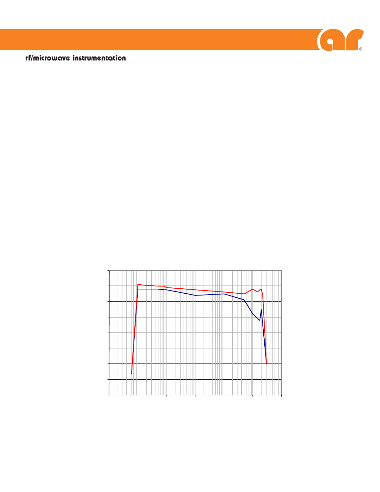
800
600A225 Typical Power Output
700
600
500
400
300
200
100
0
0.001 0.01 0.1 1 10 100 1000
PSat
P1dB
061611
160 School House Road Souderton, PA 18964-9990 • 215-723-8181 • www.ar-worldwide.com Page 1 of 3
Page 2

RATED OUTPUT POWER ............................................... 600 watts
INPUT FOR RATED OUTPUT .......................................... 1.0 milliwatt maximum
POWER OUTPUT @ 3 dB compression
Nominal ................................................................ 600 watts
Minimum ............................................................... 550 watts
POWER OUTPUT @ 1 dB compression
Nominal ................................................................ 550 watts
Minimum ............................................................... 400 watts
FLATNESS ..................................................................... 2.5 dB maximum
FREQUENCY RESPONSE ............................................... 10 kHz–225 MHz instantaneously
GAIN (at maximum setting) ........................................... 58 dB minimum
GAIN ADJUSTMENT (continuous range) ......................... 20 dB minimum
INPUT IMPEDANCE ....................................................... 50 ohms, VSWR 1.5:1 maximum
OUTPUT IMPEDANCE ................................................... 50 ohms, nominal
MISMATCH TOLERANCE ............................................... 100% rated power without foldback up to 6.0:1 mismatch, above which may
MODULATION CAPABILITY ........................................... Will faithfully reproduce AM, FM, or pulse modulation appearing on the input
HARMONIC DISTORTION ............................................. Minus 20 dBc maximum at 400 watts
THIRD ORDER INTERCEPT POINT .................................. 65 dBm typical
RF POWER DISPLAY ...................................................... 0–750 watts full scale
PRIMARY POWER .......................................................... 180–264 VAC
47–63 Hz, 2500 watts maximum @ 0.99 P.F. typical
CONNECTORS
RF input ................................................................. See Model Configuration
RF output ............................................................... See Model Configuration
Forward Sample ..................................................... BNC female on front panel (coupling factor 60 dB typical; data supplied)
Reverse Sample ...................................................... BNC female on front panel (coupling factor 60 dB typical)
Safety Interlock ....................................................... 15 pin female Type D on rear panel
REMOTE CONTROL
IEEE-488 ............................................................ 24-pin female on rear panel
RS-232 .............................................................. 9 pin female Type D on rear panel
USB ................................................................... Type B female
COOLING .................................................................... Forced air (self contained fans)
WEIGHT, maximum ...................................................... See Model Configurations
SIZE (W x H x D) ............................................................ See Model Configurations
SPECIFICATIONS, MODEL 600A225
limit to 300W reflected power. Will operate without damage or oscillation with
any magnitude and phase of source and load impedance.
signal
Page 2 of 3
Page 3

Model Number RF Input RF Output Weight Size
600A225 Type N female, front Type N female, front 45.8 kg (101 lb)
600A225M1 Type N female, rear Type N female, rear 45.8 kg (101 lb)
600A225M2 BNC female, rear 7-16 DIN female, rear 45.8 kg (101 lb)
600A225M4
600A225M5 Type N female, front 7-16 DIN female, rear 45.8 kg (101 lb)
600A225M6
600A225M7 Type N female, front Type N female, rear 45.8 kg (101 lb)
600A225M8
600A225M9
Same as 600A225M2 with enclosure removed for
Same as 600A225M1 with enclosure removed for
BNC female, rear Type N female, rear
Enclosure removed for rack mounting
Same as 600A225 with enclosure removed for rack
MODEL CONFIGURATIONS
rack mounting.
rack mounting.
mounting.
35.4 kg (78 lb)
35.4 kg (78 lb)
35.4 kg (78 lb)
35.4 kg (78 lb)
50.3 x 34 x 56.9 cm
19.8 x 13.4 x 22.0 in
50.3 x 34 x 56.9 cm
19.8 x 13.4 x 22.0 in
50.3 x 34 x 56.9 cm
19.8 x 13.4 x 22.0 in
48.3 x 30.5 x 54.4 cm
19.0 x 12.0 x 21.4 in
50.3 x 34 x 56.9 cm
19.8 x 13.4 x 22.0 in
48.3 x 30.5 x 54.4 cm
19.0 x 12.0 x 21.4 in
50.3 x 34 x 56.9 cm
19.8 x 13.4 x 22.0 in
48.3 x 30.5 x 54.4 cm
19.0 x 12.0 x 21.4 in
48.3 x 30.5 x 54.4 cm
19.0 x 12.0 x 21.4 in
Page 3 of 3
 Loading...