

Page 1
Variable Transformers
ll
Series 6000
35.0 to 315.0 Amperes
Page 2
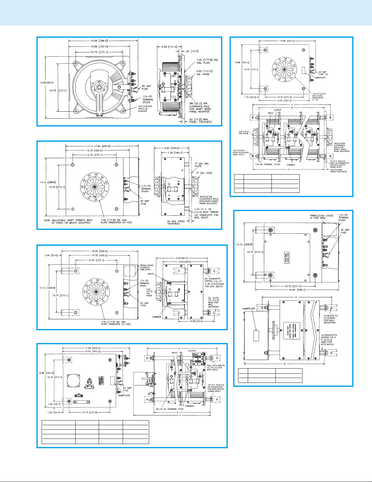
5000/6000 Series
Manual Single, Uncased
Two Ganged Three Ganged
A 17.06” [433.3] 23.12” [587.4]
B 13.56” [344.4] 19.62” [498.3]
C 15.12” [384.2] 21.19” [538.2]
Manual Single, Cased
Manual Tw o-Ganged, Cased
Manual Tw o and Three-Ganged, Uncased
Single Unit Two Ganged
A 12.94” [328.6] 19.18” [487.3]
B 15.50” [393.7] 21.56” [547.6]
A
B
C (5 sec.) 13.53” [343.7] 19.62” [498.5] 25.75” [654.0]
C (15, 30 & 60 sec.) 15.12” [384.2] 21.19” [538.2] 27.25” [692.0]
Single Unit Two Ganged Three Ganged
13.25” [336.6] 19.32” [490.7] 25.38”[644.5]
9.75” [247.7] 15.82” [401.8] 21.88”[555.7]
Motor Driven, Single,Two and Three-Ganged, Uncased
Motor Driven, Single and Two-Ganged, Cased
Page 3
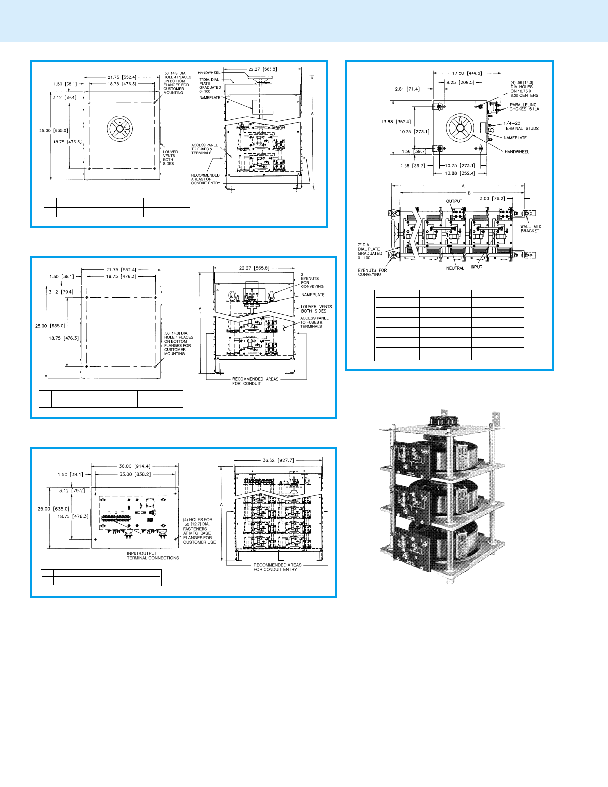
5000/6000 Series
3 Ganged 4, 5, 6 Ganged 7, 8, 9 Ganged
A
35.8” [909.32] 54.8” [1391.9] 72.8” [1849.1]
Manual Three to Nine-Ganged, Cased
AB
4 Ganged 30.38” [771.5] 27.38” [695.3]
5 Ganged 36.44”[925.5] 33.44” [849.3]
6 Ganged 42.50” [1079.5] 39.50”[1003.3]
7 Ganged 48.56” [1233.5] 45.56”[1157.3]
8 Ganged 54.62” [1387.5] 51.62”[1311.3]
9 Ganged 60.69” [1541.5] 57.69”[1465.3]
3 Ganged 4, 5, 6 Ganged 7, 8, 9 Ganged
A
33.5” [850.9] 52.5” [1333.5] 70.5”[1061.9]
Motor-Driven Three to Nine-Ganged, Cased
10 & 12 Ganged 14, 16 & 18 Ganged
A
52.5” [1333.5] 70.5” [1790.7]
Motor-Driven 10, 12, 14, 16 & 18-Ganged Open Delta and Parallel,
Cased
Manual Four to Nine-Ganged, Uncased
5021-3Y
Page 4

5000/6000 Series
12 Ganged 15 Ganged 18 Ganged 21 Ganged 24 Ganged 27 Ganged
A
36.31” [922.3] 42.38”[1076.4] 48.44” [1230.3] 54.50” [1384.3] 60.56”[1538.3] 66.62” [1692.3]
B
30.94” [786.8] 37.00” [939.8] 43.06”[1093.8] 49.12” [1247.8] 55.19” [1401.8] 61.25” [1555.8]
Motor-Driven 12, 15, 18, 21, 24 & 27-Ganged,Uncased
12, 15, 18 Ganged 21,24,27 Ganged
A
52.5” [1333.5] 70.5”[1790.7]
Motor-Driven 12, 15, 18, 21, 24 & 27-Ganged,Cased
10 Ganged 12 Ganged 14 Ganged 16 Ganged 18 Ganged
A
42.38” [1076.3] 48.44” [1230.3] 54.50”[1384.3] 60.56” [1538.3] 66.62” [1692.3]
B
37.00” [939.8] 43.06” [1093.8] 49.12” [1247.8] 55.19” [1401.8] 61.25” [1555.8]
Motor-Driven 10, 12, 14, 16 & 18-Ganged Open Delta
& Parallel, Uncased
60M5021-27Y
Page 5

6000 Series
Variable transformers of the 6011/6020 Series are designed
for larger KVA requirements. The 6011, 120 volt unit is rated
for constant current of 60 amperes. The 6020, 240 volt unit is
housing to accomodate conduit or cable connections. For three
ganged and above, we offer our Nema 1, dripproof, fully front
accessible “E” enclosure.
rated at 35 amperes for constant current loads. All single
units have coil tapping arrangements allowing output voltage
from 0 to line voltage or 17% above line voltage.
Adjustable shaft design on manually operated models permits
back-of-panel or bench mounting. Terminals are 1/4” screw
type. For single and two ganged units, case styles are available
in either “C” style, which encloses only the coil, or the “CT”
style, which provides protective housing for both the coil and
terminal board. Knockouts are provided in the terminal board
P AR T NUMBER INPUT OUTPUT SHAFT TERMINAL CONNECTIONS NET WEIGHT
MANUALLY MOTOR VOLTS HERTZ VOL TS MAX MAX VOLTAGE MA TIC
OPERA TED DRIVEN AMPS KVA INCREASE INPUT OUTPUT
6011 M6011 0-120 60 7.2
6011C M6011C
6011CT M6011CT
6020 M6020 240 50/60
6020C M6020C
6020CT M6020CT
6011-2D M6011-2D
6011C-2D M6011C-2D
6011CT-2D M6011CT-2D
6011-2P M6011-2P Single
6011C-2P M6011C-2P Phase 120 50/60
6011CT-2P M6011CT-2P Parallel
6011-2S M6011-2S Single
6011C-2S M6011C-2S Phase 240 50/60
6011CT-2S M6011CT-2S Series
6020-2D M6020-2D
6020C-2D M6020C-2D
6020CT-2D M6020CT-2D
6020-2P M6020-2P Single 240 50/60
6020C-2P M6020C-2P Phase
6020CT-2P M6020CT-2P Parallel 120 50/60 0-280
6020-2S M6020-2S Single 480 50/60
6020C-2S M6020C-2S Phase
6020CT-2S M6020CT-2S Series 240 50/60 0-560
6011-3P M6011-3P
6011E-3P M6011E-3P
6011-3Y M6011-3Y
6011E-3Y M6011E-3Y
WIRING FOR As Vie wed fr om Rotor End SCHE- (MAX)
Single
Phase
Single
Phase CCW 4-1 4-3
Three
Phase
Open
Delta
Three
Phase 0-280 35 16.9 CW 2-1-2 3-1-3
Open
Delta V.D.
Single
Phase 120 50/60
Parallel
Three
Phase 240 60
Wye
120 50/60
120 50/60 0-280
120 50/60
240 50/60
120 50/60 0-280
0-140 60 8.4
0-240 35 8.4
0-280 35 9.8
0-120 60 12.5 CW 4-1-4 3-1-3
0-140 60 14.5 CW 2-1-2 3-1-3
0-120 120 14.4 CW 1-4 1-B
0-140 120 16.8 CW 1-2 1-B
0-240 60 14.4 CW 4-4 3-3
0-280 60 16.8 CW 2-2 3-3
0-240 35 14.5 CW 4-1-4 3-1-3
0-240 70 16.8 CW 1-4 1-B
0-280 70 19.6 CW 1-2 1-B
0-480 35 16.8 CW 4-4 3-3
0-560 35 19.6 CW 2-2 3-3
0-120 180 21.6 CW 1-4 1-D
0-140 180 25.2 CW 1-2 1-D
0-240 60 24.9 CW 4-4-4 3-3-3
0-280 60 29.1 CW 2-2-2 3-3-3
35*-15
V.D. CCW 4-7 4-3
35*-15
70*-30
V. D.
35*-15
V. D.
Motor-driven models are available from single thru 27
ganged assemblies; cased or uncased (identified with the
prefix “M” in the par t number. The synchronous motor is
designed for operation on 120 volt, 50/60 Hertz lines and
draws approximately 0.3 amperes. To meet a wide range of
application requirements, standard motor speeds of 5, 15,
30 and 60 seconds are available depending upon the size of
the variable transformer.
ROTATION For Increasing Voltage IN LBS.
CW 2-4 2-3
CCW 4-2 4-3
CW 2-5 2-3
CCW 4-1 4-3
CW 2-4 2-3
CCW 4-2 4-3
CW 2-5 2-3
4.2‡
7.3‡ CW 5-1-5 3-1-3
8.4‡ CW 1-5 1-B
8.4‡ CW 5-5 3-3
CW 2-6 2-3
(Pg 8 & 9)
20 & 5 154 175
20 & 4 154 175
20 & 5 146 167
20 & 4 146 167
20 & 6 242 263
MAN- MOT OR
UAL DRIVEN
19 67 88
19 63 84
21 156 177
21 148 169
22 246 267
6011
6011
6020
Page 6

6000 Series
VIEW FROM ROTOR END
For opposite rotation interchange external
connections from 5 to 1, 2 to 4 and 6 to 7.
6011 Ganged Unit6011 Single Unit 6020 Single Unit 6020 Ganged Unit
P AR T NUMBER INPUT OUTPUT SHAFT TERMINAL CONNECTIONS NET WEIGHT
MANUALLY MOTOR VOLTS HERTZ VOL TS MAX MAX VOLTAGE MATIC
OPERA TED DRIVEN AMPS KVA INCREASE INPUT OUTPUT
6020-3P M6020-3P
6020E-3P M6020E-3P
6020-3Y M6020-3Y
6020E-3Y M6020E-3Y
6011-4D M6011-4D Phase
6011E-4D M6011E-4D Open
6011-4P M6011-4P
6011E-4P M6011E-4P
6011-4PS M6011-4PS Phase
6011E-4PS M6011E-4PS Series
6020-4D M6020-4D Phase 0-280 70 33.9 CW 2-1-2 B-1-B
6020E-4D M6020E-4D Open
6020-4P M6020-4P
6020E-4P M6020E-4P
6020-4PS M6020-4PS Phase 0-560 70 39.2 CW 2-2 B-B
6020E-4PS M6020E-4PS Series
6011-5P M6011-5P
6011E-5P M6011E-5P
6020-5P M6020-5P
6020E-5P M6020E-5P
6011-6D M6011-6D Phase
6011E-6D M6011E-6D Open
6011-6P M6011-6P
6011E-6P M6011E-6P
6011-6PS M6011-6PS Phase
6011E-6PS M6011E-6PS Series
6011-6Y M6011-6Y
6011E-6Y M6011E-6Y
WIRING FOR As Vie wed fr om Rotor End SCHE- (MAX)
Single 240 50/60
Phase
Parallel 120 50/60 0-280
Three 480
Phase
Wye 240 60 0-560
Three
0-240 105 25.2 CW 1-4 1-D
0-280 105 29.4 CW 1-2 1-D
105*-45
V. D.
50/60 0-480 35 29.1 CW 4-4-4 3-3-3
60 0-560 35 33.9 CW 2-2-2 3-3-3
35*-15
V. D.
0-120 120 24.9 CW 4-1-4 B-1-B
120 50/60
Delta
Single
Phase 120 50/60
Parallel
Single
0-140 120 29.1 CW 2-1-2 B-1-B
0-120 240 28.8 CW 1-4 1-D
0-140 240 33.6 CW 1-2 1-D
0-240 120 28.8 CW 4-4 B-B
240 50/60
Parallel
Three
Delta V.D.
240 50/60
120 50/60 0-280
Single 240 50/60
Phase
Parallel 120 50/60 0-280
Single
Parallel V. D.
480 50/60
240 50/60 0-560
Single
Phase 120 50/60
Parallel
Single 240 50/60
Phase
Parallel 120 50/60 0-280
Three
0-280 120 33.6 CW 2-2 B-B
0-240 70 29.1 CW 4-1-4 B-1-B
70*-30
0-240 140 33.6 CW 1-4 1-D
0-280 140 39.2 CW 1-2 1-D
140*-60
V. D.
0-480 70 33.6 CW 4-4 B-B
70*-30
0-120 300 36.0 CW 1-4 1-D
0-140 300 42.0 CW 1-2 1-D
0-240 175 42.0 CW 1-4 1-D
0-280 175 49.0 CW 1-2 1-D
175*-75
V. D.
0-120 180 37.4 CW 4-1-4 D-1-D
120 50/60
Delta
Single
Phase 120 50/60
Parallel
Single
0-140 180 43.6 CW 2-1-2 D-1-D
0-120 360 43.2 CW 1-4 1-D
0-140 360 50.4 CW 1-2 1-D
0-240 180 43.2 CW 4-4 D-D
240 50/60
Parallel
Three
Phase 240 60
Wye
0-280 180 50.4 CW 2-2 D-D
0-240 120 49.8 CW 4-4-4 B-B-B
0-280 120 58.1 CW 2-2-2 B-B-B
ROTATION For Increasing Voltage IN LBS.
(Pg 8 & 9)
22 246 267
12.6‡ CW 1-5 1-D
20 & 6 240 261
14.5‡ CW 5-5-5 3-3-3
21 & 5 354 375
22 356 377
21 & 4 354 375
21 & 5 338 359
14.5‡ CW 5-1-5 B-1-B
22 340 361
16.8‡ CW 1-5 1-D
21 & 4 338 359
16.8‡ CW 5-5 B-B
22 450 471
22 430 451
21.0‡ CW 1-5 1-D
22 & 5 541 562
22 543 564
22 & 4 541 562
21 & 6 539 560
MAN- MOT OR
UAL DRIVEN
Page 7

6000 Series
P AR T NUMBER INPUT OUTPUT SHAFT TERMINAL CONNECTIONS NET WEIGHT
MANUALLY MOTOR VOLTS HERTZ VOL TS MAX MAX VOLTAGE MATIC
OPERA TED DRIVEN AMPS KVA INCREASE INPUT OUTPUT
6020-6D M6020-6D Phase 0-280 105 50.9 CW 2-1-2 D-1-D
6020E-6D M6020E-6D Open
6020-6P M6020-6P
6020E-6P M6020E-6P
6020-6PS M6020-6PS Phase 0-560 105 58.8 CW 2-2 D-D
6020E-6PS M6020E-6PS Series
6020-6Y M6020-6Y
6020E-6Y M6020E-6Y
6011-7P M6011-7P
6011E-7P M6011E-7P
6020-7P M6020-7P
6020E-7P M6020E-7P
6011-8D M6011-8D Phase
6011E-8D M6011E-8D Open
6011-8P M6011-8P
6011E-8P M6011E-8P
6011-8PS M6011-8PS Phase
6011E-8PS M6011E-8PS Series
6020-8D M6020-8D Phase 0-280 140 67.8 CW 2-1-2 D-1-D
6020E-8D M6020E-8D Open
6020-8P M6020-8P
6020E-8P M6020E-8P
6020-8PS M6020-8PS Phase 0-560 140 78.4 CW 2-2 D-D
6020E-8PS M6020E-8PS Series
6011-9P M6011-9P
6011E-9P M6011E-9P
6011-9Y M6011-9Y
6011E-9Y M6011E-9Y
6020-9P M6020-9P
6020E-9P M6020E-9P
6020-9Y M6020-9Y
6020E-9Y M6020E-9Y
M6011-10D Phase
—
M6011E-10D Open
M6011-10PS Phase
—
M6011E-10PS Series
M6020-10D Phase 0-280 175 84.8 CW 2-1-2 D-1-D
—
M6020E-10D Open
WIRING FOR As Vie wed fr om Rotor End SCHE- (MAX)
Three
Delta V.D.
Single
Phase
Parallel
Single
Parallel V. D.
Three 480
Phase
Wye 240 60 0-560
Single
Phase 120 50/60
Parallel
Single 240 50/60
Phase
Parallel 120 50/60 0-280
Three
Delta
Single
Phase 120 50/60
Parallel
Single
Parallel
Three
Delta V.D.
Single 240 50/60
Phase
Parallel 120 50/60 0-280
Single
Parallel V. D.
Single
Phase 120 50/60
Parallel
Three
Phase 240 60
Wye
Single 240 50/60
Phase
Parallel 120 50/60 0-280
Three 480
Phase
Wye 240 60 0-560
Three
Delta
Single
Parallel
Three
Delta V.D.
240 50/60
120 50/60 0-280
240 50/60
120 50/60 0-280
480 50/60
240 50/60 0-560
120 50/60
240 50/60
240 50/60
120 50/60 0-280
480 50/60
240 50/60 0-560
120 50/60
240 50/60
240 50/60
120 50/60 0-280
0-240 105 43.6 CW 4-1-4 D-1-D
105*-45
0-240 210 50.4 CW 1-4 1-D
0-280 210 58.8 CW 1-2 1-D
210*-90
V. D.
0-480 105 50.4 CW 4-4 D-D
105*-45
50/60 0-480 70 58.1 CW 4-4-4 B-B-B
60 0-560 70 67.8 CW 2-2-2 B-B-B
50/60 0-480 105 87.2 CW 4-4-4 D-D-D
60 0-560 105 101.7 CW 2-2-2 D-D-D
70*-30
V. D.
0-120 420 50.4 CW 1-4 1-D
0-140 420 58.8 CW 1-2 1-D
0-240 245 58.8 CW 1-4 1-D
0-280 245 68.6 CW 1-2 1-D
245*-105
V. D.
0-120 240 49.8 CW 4-1-4 D-1-D
0-140 240 58.1 CW 2-1-2 D-1-D
0-120 480 57.6 CW 1-4 1-D
0-140 480 67.2 CW 1-2 1-D
0-240 240 57.6 CW 4-4 D-D
0-280 240 67.2 CW 2-2 D-D
0-240 140 58.1 CW 4-1-4 D-1-D
140*-60
0-240 280 67.2 CW 1-4 1-D
0-280 280 78.4 CW 1-2 1-D
280*-120
V. D.
0-480 140 67.2 CW 4-4 D-D
140*-60
0-120 540 64.8 CW 1-4 1-D
0-140 540 75.6 CW 1-2 1-D
0-240 180 74.7 CW 4-4-4 D-D-D
0-280 180 87.2 CW 2-2-2 D-D-D
0-240 315 75.6 CW 1-4 1-D
0-280 315 88.2 CW 1-2 1-D
315*-135
V. D.
105*-45
V. D.
0-120 300 62.3 CW 4-1-4 D-1-D
0-140 300 72.7 CW 2-1-2 D-1-D
0-240 300 72.0 CW 4-4 D-D
0-280 300 84.0 CW 2-2 D-D
0-240 175 72.7 CW 4-1-4 D-1-D
175*-75
ROTATION For Increasing Voltage IN LBS.
(Pg 8 & 9)
21.8‡ CW 5-1-5 D-1-D
25.2‡ CW 1-5 1-D
25.2‡ CW 5-5 D-D
29.1‡ CW 5-5-5 B-B-B
29.4‡ CW 1-5 1-D
29.1‡ CW 5-1-5 D-1-D
33.6‡ CW 1-5 1-D
33.6‡ CW 5-5 D-D
37.8‡ CW 1-5 1-D
43.6‡ CW 5-5-5 D-D-D
36.3‡ CW 5-1-5 D-1-D
22 & 5 517 538
22 489 510
22 & 4 487 508
21 & 6 485 506
22 633 654
22 598 619
22 & 5 720 741
22 722 743
22 & 4 720 741
22 & 5 688 709
22 690 711
22 & 4 688 709
22 811 832
22 & 6 807 828
22 775 796
22 & 6 771 792
22 & 5 — 912
22 & 4 — 912
22 & 5 — 912
MAN- MOT OR
UAL DRIVEN
Page 8

6000 Series
P AR T NUMBER INPUT OUTPUT SHAFT TERMINAL CONNECTIONS NET WEIGHT
MANUALLY MOTOR VOLTS HERTZ VOL TS MAX MAX VOLTAGE MATIC
OPERA TED DRIVEN AMPS KVA INCREASE INPUT OUTPUT
M6020-10PS Phase 0-560 175 98.0 CW 2-2 D-D
—
M6020E-10PS Series
M6011-12D Phase
—
M6011E-12D Open
M6011-12PS Phase
—
M6011E-12PS Series
M6020-12D Phase 0-280 210 101.7 CW 2-1-2 D-1-D
—
M6020E-12D Open
M6020-12PS Phase 0-560 210 117.6 CW 2-2 D-D
—
M6020E-12PS Series
M6011-14D Phase
—
M6011E-14D Open
M6011-14PS Phase
—
M6011E-14PS Series
M6020-14D Phase 0-280 245 118.7 CW 2-1-2 D-1-D
—
M6020E-14D Open
M6020-14PS Phase 0-560 245 137.2 CW 2-2 D-D
—
M6020E-14PS Series
M6011-16D Phase
—
M6011E-16D Open
M6011-16PS Phase
—
M6011E-16PS Series
M6020-16D Phase 0-280 280 135.6 CW 2-1-2 D-1-D
—
M6020E-16D Open
M6020-16PS Phase 0-560 280 156.8 CW 2-2 D-D
—
M6020E-16PS Series
M6011-18D Phase
—
M6011E-18D Open
M6011-18PS Phase
—
M6011E-18PS Series
M6020-18D Phase 0-280 315 152.6 CW 2-1-2 D-1-D
—
M6020E-18D Open
M6020-18PS Phase 0-560 315 176.4 CW 2-2 D-D
—
M6020E-18PS Series
M6011-12Y
—
M6011E-12Y
WIRING FOR As Vie wed fr om Rotor End SCHE- (MAX)
Single
Parallel V. D.
Three
Delta
Single
Parallel
Three
Delta V.D.
Single
Parallel V. D.
Three
Delta
Single
Parallel
Three
Delta V.D.
Single
Parallel V. D.
Three
Delta
Single
Parallel
Three
Delta V.D.
Single
Parallel V. D.
Three
Delta
Single
Parallel
Three
Delta V.D.
Single
Parallel V. D.
Three
Phase 240 60
Wye
480 50/60
240 50/60 0-560
120 50/60
240 50/60
240 50/60
120 50/60 0-280
480 50/60
240 50/60 0-560
120 50/60
240 50/60
240 50/60
120 50/60 0-280
480 50/60
240 50/60 0-560
120 50/60
240 50/60
240 50/60
120 50/60 0-280
480 50/60
240 50/60 0-560
120 50/60
240 50/60
240 50/60
120 50/60 0-280
480 50/60
240 50/60 0-560
0-480 175 84.0 CW 4-4 D-D
175*-75
0-120 360 74.7 CW 4-1-4 D-1-D
0-140 360 87.2 CW 2-1-2 D-1-D
0-240 360 86.4 CW 4-4 D-D
0-280 360 100.8 CW 2-2 D-D
0-240 210 87.2 CW 4-1-4 D-1-D
210*-90
0-480 210 100.8 CW 4-4 D-D
210*-90
0-120 420 87.2 CW 4-1-4 D-1-D
0-140 420 101.7 CW 2-1-2 D-1-D
0-240 420 100.8 CW 4-4 D-D
0-280 420 117.6 CW 2-2 D-D
0-240 245 101.7 CW 4-1-4 D-1-D
245*-105
0-480 245 117.6 CW 4-4 D-D
245*-105
0-120 480 99.6 CW 4-1-4 D-1-D
0-140 480 116.3 CW 2-1-2 D-1-D
0-240 480 115.2 CW 4-4 D-D
0-280 480 134.4 CW 2-2 D-D
0-240 280 116.3 CW 4-1-4 D-1-D
280*-120
0-480 280 134.4 CW 4-4 D-D
280*-120
0-120 540 112.1 CW 4-1-4 D-1-D
0-140 540 130.8 CW 2-1-2 D-1-D
0-240 540 129.6 CW 4-4 D-D
0-280 540 151.2 CW 2-2 D-D
0-240 315 130.8 CW 4-1-4 D-1-D
315*-135
0-480 315 151.2 CW 4-4 D-D
315*-135
0-240 240 99.6 CW 4-4-4 D-D-D
0-280 240 116.3 CW 2-2-2 D-D-D
ROTATION For Increasing Voltage IN LBS.
(Pg 8 & 9)
22 & 4 — 872
42.0‡ CW 5-5 D-D
22 & 5 — 1060
22 & 4 — 1060
22 & 5 — 1012
43.6‡ CW 5-1-5 D-1-D
22 & 4 — 1012
50.4‡ CW 5-5 D-D
22 & 5 — 1237
22 & 4 — 1237
22 & 5 — 1181
50.9‡ CW 5-1-5 D-1-D
22 & 4 — 1181
58.8‡ CW 5-5 D-D
22 & 5 — 1414
22 & 4 — 1414
22 & 5 — 1350
58.1‡ CW 5-1-5 D-1-D
22 & 4 — 1350
67.2‡ CW 5-5 D-D
22 & 5 — 1597
22 & 4 — 1597
22 & 5 — 1525
94.5‡ CW 5-1-5 D-1-D
22 & 4 — 1525
75.6‡ CW 5-5 D-D
22 & 6 — 1062
MAN- MOT OR
UAL DRIVEN
Page 9

6000 Series
P AR T NUMBER INPUT OUTPUT SHAFT TERMINAL CONNECTIONS NET WEIGHT
MANUALLY MOTOR VOLTS HERTZ VOL TS MAX MAX VOLTAGE MATIC
OPERA TED DRIVEN AMPS KVA INCREASE INPUT OUTPUT
M6020-12Y
—
M6020E-12Y
M6011-15Y
—
M6011E-15Y
M6020-15Y
—
M6020E-15Y
M6011-18Y
—
M6011E-18Y
M6020-18Y
—
M6020E-18Y
M6011-21Y
—
M6011E-21Y
M6020-21Y
—
M6020E-21Y
M6011-24Y
—
M6011E-24Y
M6020-24Y
—
M6020E-24Y
M6011-27Y
—
M6011E-27Y
M6020-27Y Three 60 0-560 315 305.2 CW 2-2-2 D-D-D
—
M6020E-27Y Phase
WIRING FOR As Vie wed fr om Rotor End SCHE- (MAX)
Three 480
Phase
Wye 240 60 0-560
Three
Phase 240 60
Wye
Three 480
Phase
Wye 240 60 0-560
Three
Phase 240 60
Wye
Three 480
Phase
Wye 240 60 0-560
Three
Phase 240 60
Wye
Three 480
Phase
Wye 240 60 0-560
Three
Phase 240 60
Wye
Three 480
Phase
Wye 240 60 0-560
Three
Phase 240 60
Wye
Wye V .D.
50/60 0-480 140 116.3 CW 4-4-4 D-D-D
60 0-560 140 135.6 CW 2-2-2 D-D-D
50/60 0-480 175 145.3 CW 4-4-4 D-D-D
60 0-560 175 169.5 CW 2-2-2 D-D-D
50/60 0-480 210 174.6 CW 4-4-4 D-D-D
60 0-560 210 203.4 CW 2-2-2 D-D-D
50/60 0-480 245 203.4 CW 4-4-4 D-D-D
60 0-560 245 237.4 CW 2-2-2 D-D-D
50/60 0-480 280 232.5 CW 4-4-4 D-D-D
60 0-560 280 271.3 CW 2-2-2 D-D-D
50/60 0-480 315 261.6 CW 4-4-4 D-D-D
480
240 60 0-560
140*-60
V. D.
0-240 300 124.6 CW 4-4-4 D-D-D
0-280 300 145.3 CW 2-2-2 D-D-D
175*-75
V. D.
0-240 360 149.5 CW 4-4-4 D-D-D
0-280 360 174.4 CW 2-2-2 D-D-D
210*-90
V. D.
0-240 420 174.4 CW 4-4-4 D-D-D
0-280 420 203.4 CW 2-2-2 D-D-D
245*-105
V. D.
0-240 480 199.3 CW 4-4-4 D-D-D
0-280 480 232.5 CW 2-2-2 D-D-D
280*-120
V. D.
0-240 540 224.2 CW 4-4-4 D-D-D
0-280 540 261.6 CW 2-2-2 D-D-D
315*-135
ROTATION For Increasing Voltage IN LBS.
(Pg 8 & 9)
22 & 6 — 1014
58.1‡ CW 5-5-5 D-D-D
22 & 6 — 1329
22 & 6 — 1269
72.7‡ CW 5-5-5 D-D-D
22 & 6 — 1595
22 & 6 — 1523
87.2‡ CW 5-5-5 D-D-D
22 & 6 — 1864
22 & 6 — 1780
101.7‡ CW 5-5-5 D-D-D
22 & 6 — 2132
22 & 6 — 2036
116.3‡ CW 5-5-5 D-D-D
22 & 6 — 2401
22 & 6 — 2293
130.8‡ CW 5-5-5 D-D-D
MAN- MOT OR
UAL DRIVEN
* Maximum output current in output voltage range from 0 to 25 percent above line voltage.At higher output voltages, output current m ust be reduced according
to rating curve Figure B, page 6.
‡ Maximum KVA at maximum output and corresponding de-rated current. Maximum KVA at lower output voltages may be calculated from rating curve Figure B,
page 6.
V. D. Voltage Doubler
 Loading...