

Page 1
SYNC AND TIMING
58503B
GPS Time and Frequency Reference Receiver
KEY FEATURES
• SmartClock Technology
• Designed for R&D Labs, Manufacturing
and Calibration Labs
• Low Cost Source for Precision Time
and Frequency
INTRODUCTION
The Symmetricom 58503B GPS time and
frequency reference receiver is a high quality
source of precision time, time interval, and
frequency in a lightweight compact package.
The high-performance 58503B ensures
excellent accuracy and reliability—the 58503B
delivers precise time and frequency virtually
anywhere in the world at an affordable price.
When locked to the GPS signal, the 58503B
provides a 10 MHz signal with an accuracy of
better than 1
1 pulse per second (1 PPS) signal with timing
<
jitter of
racy relative to GPS of 20ns (1 Sigma, typical)
can be obtained once the unit is properly
installed and all systematic offsets have been
compensated out.
If the GPS signal is interrupted, the 58503B
enters an intelligent holdover mode, which
ensures frequency is maintained to better
than 1
<
which does this is called SmartClock.™
750 ps rms is provided. Time accu-
×
10
8.6 µsec after 24 hours). The technology
–12
×
10
using a 1 day average. A
–10
per day (phase accumulation
SMARTCLOCK
SmartClock technology contributes
significantly to the performance of the
58503B GPS time and frequency reference
receiver. SmartClock learns and corrects for
the effects of oscillator aging and temperature.
This technology, combined with a highly reliable
oscillator, contributes to the superior price,
performance, size and reliability delivered by
the 58503B.
FIG.1 58503B GPS Time and Frequency Receiver
Page 2
714600
714500
714400
714300
714200
EFC COMMAND
714100
START
714000
3 DAY LEARNING PERIOD
713900
713800
01234567
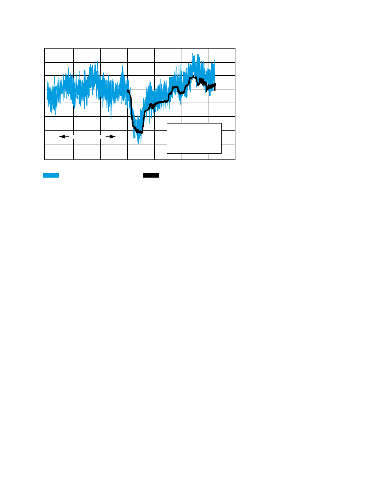
FIG.2 SmartClock operation
TIME (DAYS)
ACTUAL STEERING COMMAND
PREDICTED STEERING COMMAND
DAY
ACCUM.
OF
TIME
ERROR
4
1.74∞S
5
6
4.03
7.50
AVG.
FREQ.
2.04e-11
2.63e-11
4.07e-11
SMARTCLOCK TECHNOLOGY
Integrated with the quartz oscillator,
SmartClock greatly enhances the performance
of the 58503B GPS time and frequency
reference receiver under both locked and
unlocked conditions. In the locked condition,
it has all the desirable short-term stability
attributes of a state-of-the-art quartz
oscillator, but it is drift free. In the event the
GPS reference is lost, the combination of the
quartz oscillator and SmartClock delivers
performance which approaches the
performance of rubidium oscillators.
Figure 2 gives typical data illustrating the
operation of SmartClock. All data is taken
with the unit locked to GPS. During the first
three days, SmartClock uses the GPS reference
to “learn” the aging behavior of the quartz
oscillator. This information, along with the
temperature compensation that is taught to
SmartClock when the unit is tested at the
factory, is used to steer the oscillator. The
light, shaded line shows the actual digital
steering commands sent to the oscillator to
keep it synchronized with GPS time.
The heavy, solid line shows a plot of the steering
commands computed using the SmartClock
algorithm starting with Day 4. The dominant
effects during the predicting period are changes
due to external temperature. If the GPS signal
had not been present, the oscillator would
have been steered in holdover by SmartClock
using the corrections that it had determined
from the learning period.
Holdover performance can be computed from
the difference between the actual steered
performance and the predicted performance.
The data for the first three days in holdover
are shown in Figure 2.
ENHANCED GPS
Enhanced GPS includes digital filtering
designed to remove most of the effects of
SA (Selective Availability) on the timing
performance of the 58503B.
Enhanced GPS is based on extensive study of
the spectrum of SA, a method superior to
simple averaging techniques. Enhanced GPS
couples SA data with clock instability models
to derive optimum digital filters which minimize
the effects of SA. The benefits of Enhanced
GPS apply only to stationary 58503B GPS
time and frequency reference receivers.
When a Symmetricom GPS receiver is initially
turned on and locked to the GPS satellite
system, it will achieve GPS lock within 30
minutes of operation. It has a 95% probability
of meeting unlocked (holdover) specifications
after 48 hours of GPS operation, followed by
24 hours of learning. The longer the GPS
receiver (and its quartz oscillator) operates,
the better its stability and unlocked
(holdover) performance becomes.
SATSTAT PROGRAM
The Symmetricom 58503B comes with a
Microsoft
“SatStat” which displays important internal
parameters. SatStat operates on any PC
which can run Windows 3.1 programs and
which has a serial interface available.
SatStat provides several useful functions. It
continuously polls the RS-232 interface and
displays receiver information most likely to
be of interest. This includes satellites being
tracked along with their elevation and
azimuth, receiver state (locked, holdover,
etc.), antenna coordinates, time and frequency
figures of merit and other data. In addition, a
clock window is provided to display time of
day in real time. Finally, SatStat allows you to
easily change many receiver parameters,
such as antenna delay, by simply picking the
item from a pop-up menu and entering a new
value. With SatStat and a PC, you can monitor
and control many aspects of the receiver status
without developing software.
®
Windows 3.1 program called
2
Page 3

OPTIONAL 16-CHARACTER FRONT
PANEL DISPLAY
Available options include a built-in front panel
display. The standard 58503B GPS time and
frequency reference receiver does not include
a display. While a display is not necessary, it
may be convenient to track the receiver’s
progress during installation and startup by
monitoring the satellites being tracked,
location, time, and other parameters.
OPTIONAL 1 PP2S OUTPUT
(EVEN-SECOND OOUTPUT)
An even-second (1 PP2S) output is available
as an option to the 58503B. The even-second
output option provides one pulse every other
second, synchronized to the even seconds in
GPS time. This is the reference time used in
CDMA base stations. GPS even-second pulses
from the 1 PP2S option are used to synchronize
the Agilent 8921A (Option 600) and the Agilent
8935A cellular base station test sets.
Synchronizing the test set from an independent
source permits remote base station testing
and independent base station frequency and
time reference accuracy checks.
TIME DOMAIN STABILITY
-10
1 x 10
-11
1 x 10
-12
1 x 10
ROOT ALLEN VARIANCE
-13
1 x 10
-14
1 x 10
.01
FIG.3 Time Domain Stability
0.1 1 10 100 1000 10000 100000 1000000
TYPICAL PERFOMANCE
Locked to GPS
SAMPLE TIME (SECONDS)
SPECIFICATION
58503B SPECIFICATIONS AND CHARACTERISTICS
GPS RECEIVER FEATURES
GENERAL SPECIFICATIONS
• Eight channel, parallel tracking GPS engine
• C/A Code, L1 Carrier
• SmartClock/ Enhanced GPS
• Optional DC power operation available
ANTENNA AND CABLING
INFORMATION
The 58532A GPS L1 Reference antenna is
recommended to ensure specified performance
of the 58503B. For optimum performance,
the antenna should be installed in a location
which gives it a clear view of the entire sky.
TYPE
• Active antenna
• Power supplied to the 5 volts nominal
antenna by the 58503B 50 mA max
ANTENNA CONNECTOR (58503B)
• Type N jack (female).
ANTENNA CABLE
• 58521A cables are recommended. These cables are
LMR 400 with Type-N connectors (male) on both ends.
A variety of lengths are available.
ADDITIONAL ACCESSORIES
• 58502A broadband distribution amplifier; provides
12-Channel broadband (0.1 to 10 MHz) sine wave distribution.
• 58535A/36A/17A GPS L1 signal distribution
amplifiers/splitters allows multiple receivers (2, 4, or 8)
to share a single antenna.
• 58529A GPS line amplifier with L1 bandpass filter;
provides the gain to overcome cable loss and protection
against noise and interference signals.
• 58530A GPS L1 bandpass filter; provides protection
against noise and interference signals
• 58538A/ 58539A lightning arrestors; provides protection
against nearby lightning strikes.
10 MHz Output Specifications (with SA on)
LOCKED
• Frequency Accuracy: Better than 1 × 10
UNLOCKED
• Holdover aging: <1 × 10
unlocked operation. (See Notes 1 and 2.)
PHASE NOISE (LOCKED)
• Offset From Signal (Hz) SSB Phase Noise (dBc)
1 -85
10 -125
100 -135
1000 -140
10000 -145
TIME DOMAIN STABILITY (LOCKED)
(See Figure 3)
• Averaging Time Seconds Root Allan Variance
0.01 1.5 × 10
0.1 1.5 × 10
15 × 10
10 5 × 10
100 5 × 10
1000 5 × 10
SUPPLEMENTAL INFORMATION
• Waveform Sine wave
• Amplitude >1.7 volts p-p (+8 to +10 dBm) into a 50 Ω load
• Harmonic Distortion <–25 dBc (Typical)
• Non-harmonic signals <–80 dBc (Typical)
• Source impedance 50Ω (nominal)
• Coupling AC
• Connector BNC
–10
per day average frequency change in 24 hours of
-12
, for a one day average, 0 ºC to 50 ºC.
–10
–11
–12
–12
–11
–11
3
Page 4

1 PPS Output/1 PP2S Output (Option 002) Specifications
(with SA on)
LOCKED
Jitter of leading edge: <750 ps rms with at least one satellite in view.
TIME ACCURACY
20ns typical (1 Sigma) SA off with respect to UTC (USNO MC) and all systematic
offsets have been removed, calibrated, and locked to GPS.
UNLOCKED
Accumulated time error: <8.6 µs accumulated in 24 hours of unlocked operation.
(See Notes 1 and 2.)
SUPPLEMENTAL INFORMATION
• Pulse Width 26 µs
• Amplitude >2.4 volts into 50 W load. (TTL compatible)
• Connector BNC
• Rise time 40 ns typical
ADDITIONAL FEATURES
ALARM OUTPUT
TTL open collector with internal pull-up resistor. Circuit can sink up to 10 ma.
Provides a logic output to allow monitoring of normal (H) and abnormal (L)
operation externally and remotely. BNC connector.
FRONT PANEL INDICATORS (LEDs)
•Power
• GPS Lock
• Holdover Mode
• Alarm
REMOTE INTERFACE
• RS-232C DTE configuration Complete remote control and interrogation of all
• Factory defaults Baud rate 9600, 8 data bits, 1 start bit, 1 stop bit, no parity.
• Connector 25-pin female rectangular D subminiature on rear panel.
• Time code output is available to a computer immediately preceding the 1 PPS signal
for the current second.
instrument functions and parameters.
Other settings are programmable.
ENVIRONMENTAL SPECIFICATIONS
TIME AND FREQUENCY REFERENCE RECEIVER (58503B)
Operating 0° C to +50° C
Storage -40° C to +80° C
ANTENNA (58532A)
Operating -40° C to +85° C
Storage -45° C to +90° C
Additional Information
POWER REQUIREMENTS
• AC power (standard)
AUTO RANGING
• 100 -127 Vac, nominal
• 220 - 240 Vac, nominal
RANGES
• 90 - 132 Vac
• 198 - 264 Vac
• 47 - 63 Hz
Option AWQ (replaces AC power operation with
DC power operation)
AUTO RANGING
• 24 - 48 Vdc, nominal
RANGE
• 20 - 60 Vdc, greater than +23 Vdc required to start
INPUT POWER (all options)
• <35 watts (nominal)
DIMENSIONS
• 88.5 mm H x 212.6 mm W x 348.3 mm D
Half-rack module.
NOTE 1
This specification has a 95% probability, and is based on the availability of four or more
GPS satellites during three days of locked operation with a fixed antenna location. The
temperature must remain within a 10 ºC range between 10 ºC and 40 ºC.
NOTE 2
When a quartz oscillator has not been operated for a period of time, or if it has been
subjected to severe thermal or mechanical shock as might be encountered during
product shipment, the oscillator may take some time to stabilize. In most cases, the
oscillator will drift and then stabilize at or below its specified rate within a few days
after being turned on. In isolated cases, depending upon the amount of time the oscillator
has been off and the environmental conditions it has experienced, the oscillator may
take up to one week to reach its specified aging rate and to operate without significant
frequency “jumps.”
When a Symmetricom GPS receiver is initially turned on and locked to the GPS satellite
system, it will achieve GPS lock within 30 minutes of operation. It has a 95% probability
of meeting unlocked (holdover) specifications after 48 hours of GPS operation, followed
by 24 hours of learning. The longer the GPS receiver (and its quartz oscillator) operates,
the better its stability and unlocked (holdover) performance becomes.
SYMMETRICOM, INC.
2300 Orchard Parkway
San Jose, California
95131-1017
tel : 408.433.0910
fax : 408.428.7896
info@symmetricom.com
www.symmetricom.com
SYMMETRICOM EMEA
150 Wharfedale Road
Winnersh Triangle, Nr. Wokingham
Berkshire
RG41 5RB, United Kingdom
tel : 44.1189.699799
fax : 44.1189.277520
info@symmetricom.com
©2002 Symmetricom. Symmetricom and the Symmetricom logo are registered trademarks of Symmetricom, Inc. All specifications
subject to change without notice. DS/58503B/D/0902/PDF
SYMMETRICOM LATIN AMERICA
1560 Sawgrass Corporate Parkway
4th Floor
Sunrise, Florida
33323
tel : 954.331.4592
fax : 954.331.4601
info@symmetricom.com
SYMMETRICOM ASIA ACIFIC
Unit 1005, Jubilee Centre
42–46 Gloucester Road
Wan Chai
Hong Kong
tel : 852.2529.7180
fax : 852.2529.7190
info@symmetricom.com
 Loading...