

Page 1
Elgar ■1.800.733.5427 ■858.450.0085 ■Fax 858.458.0267 ■9250 Brown Deer Road, San Diego, CA 92121 ■www.elgar.com ■email: sales@elgar.com
20
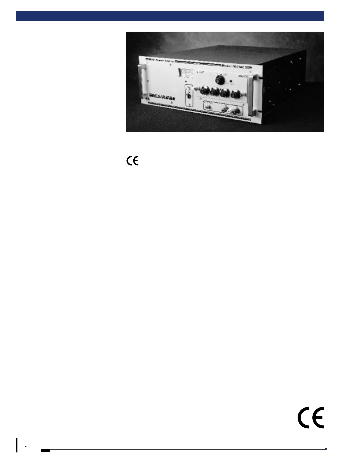
SL AND B SERIES
PRODUCT OVERVIEW
Elgar SL and B Series power sources are
wide range, solid-state linear amplifiers
that convert the incoming line to low
distortion, stable sine wave power.
These solid-state frequency changers are
benchtop/19" rackmount units that can be
driven over their full voltage and frequency
ranges by fixed, variable or programmable
plug-in oscillators.
The SL and B’s offer overload and overtemperature protection, can operate
continuously at up to 150% rated capacity,
and provide up to three output voltage ranges.
FEATURES AND
BE N E FITS
CONTINUOUS DUTY AT
150% RATED CAPACITY
Due to their conservative design, the
SL Series provides continuous duty at 150%
rated capacity into a linear resistive load,
while the B Series models are rated at 100%.
LOW HARMONIC DISTORTION
The SL and B Series power sources
provide low harmonic distortion normally
below 0.3% midband, 0.6% over the full
frequency range.
WIDE FREQUENCY RANGE
Elgar AC power sources offer frequencies
from 45 Hz to 5 kHz at full rated power.
(optionally expandable to 10 kHz)
CONFIGURABLE
SL and B Series components can b e used
as building blocks for creating a full
range of single, dual and three-phase AC
power sources.
OUTPUT POWER VOLT AMPERE
RATING
Single phase 120 VA to 18 kVA
Dual phase 240 VA to 18 kVA
Three phase 150 VA to 36 kVA
WARRANTY
Elgar offers a two year warranty on the SL
and B Series power supplies.
EMC/ SA FET Y (S LE Models Only)
The 1001 SLE and 1751 SLE have
been designed to meet the
requirements for the CE mark.
OPTIONS
PROG RAMMABLE VIA IE E E -448 G P IB
Elgar’s SL and B Series, when used w ith a
Plug-In Programmer, provide full G PIB
control of voltage, frequency, phase angle,
voltage dropouts and test readback of
output parameters.
RANGE CHANGE RELAYS
An optional internal range change relay
switches between 130 VAC and 260 VAC
ranges under GPIB control or front panel
local control when used with a P I P or a
modified oscillator.
TEST OPTION/BUILT-IN
TEST E Q U IPME NT (BIT E)
This feature is available when used with
an Elgar PIP9 012A, PIP9 023 or P I P704 that
also has the test option. Depending on the
PIP, the R MS voltage, RM S current,
frequency, phase angle and true power in
watts can be read from the front panel or
over the GPIB.
PROGRAMMABLE CURRENT LIMIT
When equipped w ith the test option (Builtin Test Equipment/B IT E), a current limit may
be programmed via the GPIB or from the
front panel which, if exceeded, will cause
system shutdown and status reporting.
REMOTE SENSE
This feature provides full programming
accuracy without sacrificing response time
and is available with Elgar Plug-In
Programmers and other selected oscillators
for 0.015% regulation .
DISCONNECT RELAY
The optional internal output relay connects
the load to the output of the power source
under GPIB control or from the front panel
keypad with a Plug-In Programmer.
APPLICATIONS
The linear design of the SL and B Series
provides a highly regulated, clean sine
wave, making these units ideal for linear
loads in general purpose test applications
as well as for Automatic Test Equipment
systems and avionics testing.
■
Power fault simulation when used
with an Elgar Plug-In Programmer
■
Frequency conversion (60 to 50 Hz
or 50 to 60 Hz) for generating
international or USA power
■
Power supply testing
■
Gyro testing
■
Avionics testing (400 Hz)
1001 SL and 400 SD
Page 2
Elgar ■1.800.733.5427 ■858.450.0085 ■Fax 858.458.0267 ■9250 Brown Deer Road, San Diego, CA 92121 ■www.elgar.com ■email: sales@elgar.com
21
SL AND B SERIES SPECIFICATIONS
SPECIFICATIONS
OUTPUT
Voltage Range: SL Series: 0-65, 0-130,
0-260 VAC; B Series: 0-32, 0-65, 0-130,
0-260 VAC (varies per model). Specific
output range is selected by jumper change
on rear panel. Consult Elgar for other voltage
ranges.
Rated Power Voltage Range: Full rated
VA from 55-65 VAC, 110-130 VAC, or
220-260 VAC over a ±10% input and rated
PF range
SL Series: Continuous duty at 150% of
rated capacity at 55C°*
B Series: Continuous duty at 100% of
rated capacity*
Load Power Factor: Unity to ±0.7 PF at
rated VA with an output voltage
adjustment range of 85-100% of full scale*
Frequency Range: 45 Hz to 5 kHz at full
rated power
Total Harmonic Distortion:
SL Series:0.4% 200 Hz to 1000 Hz
0.6% Full frequency range
B Series: 0.5% 100 Hz to 1000 Hz
0.9% Full frequency range
Load Regulation: ±1% no load to full
load over full frequency range. Better than
±0.25% for fixed frequency output.
Adjustable to ±0.1% for specific load
conditions and to ±0.015% with a PIP
Line Regulation: ±0.25% at rated load
for a ±10% input change at full scale
output voltage
Response Time: < 50 microseconds
AC Noise Level: 70 dB below full output
voltage with input grounded
INPUT
Voltage S L Series: See mo del numb er
description on page 23.
Three Phase B Series Models: See table
Frequency: 47 to 63 Hz (400 Hz option,
special order)
Efficiency: Up to 45%
GENERAL
Operating Temperature Range: 0° to
+55°C
Operating Humidity Range: Up to 95%
non-condensing
Metering: SL Series: 0-300 VAC output
voltmeter, ±3% accuracy
B Series: 0-150 VAC
Controls: Input power switch/circuit
breaker and pilot light. Full range, 10-turn
output voltage control potentiometer
*See Power Rating Curve on page 23.
Single Phase Output Power
Model Power Output Input Physical Comments
Total VA Vol . Range Max Current Frequency Voltage and Nominal/ Max Height and Depth Weight WT
(RMS)L-N (RMS)1Range (Hz) Phase (kVA)
2
(in/mm) (lbs/kg)
121B 120 0-130 1.1 45 to 5k 115 or 230, 1ø 0.4 3.5/89 H 47/21 Net 0-32V/4.4A range available;
0-260 0.55 5/127 D 51/23 Ship Model 121B-101
251B 250 0-32 9.2 45 to 5k 115 or 230, 1ø 0.8 5.25/133 H 49/22 Net
0-130 2.25 16/405 D 55/25 Ship
0-260 1.1
351 SL-XX 350 0-65 8.0 45 to 5k 115 or 230, 1ø 1.0/1.6 5.25/133 H 75/34 Net
0-130 4.0 21/533 D 83/38 Ship
0-260 2.0
501 SL-XX 500 0-65 11.5 45 to 5k 115 or 230, 1ø 1.5/2.2 5.25/133 H 80/36 Net
0-130 5.8 21/533 D 88/40 Ship
0-260 2.9
751 S L-XX 750 0-65 17.3 45 to 5k 115, 208 or 2.2/3.2 7.00/178 H 115/52 Net
0-130 8.65 230, 1ø 21/533 D 25/57 Ship
0-260 4.3
1001 S L- XX 1000 0-65 23.1 45 to 5k 115, 208 or 3.0/4.2 7.00/178 H 125/57 Net
& 0-130 11.5 230, 1ø 21/533 D 135/61 Ship
1001 SLE-2X 0-260 5.8 1001 SLE-21 only
1751 S L -X X 1750 0-65 40.4 45 to 5k 115, 208 or 5.2/7.5 12.25/311 H 190/86 Net
& 0-130 20.2 230, 1ø 21/533 D 200/91 Ship
1751 SLE-2X 0-260 10.1 1751 SLE-21 only
3001 3000 0-65 54.5 45to 3k 208 or 416 9.0 17.5/445 H 315/143 Net
0-130 27.2 L-L, 3 ø 22/560 D 361/164 Ship
0-260 13.6
3500 SL-XX 3500 0-65 80.8 45 to 5k 115, 208 10.5/15.0 24.50/622 H 380/172 Net 2ea 1751 SL, 1 ea 400 SR,
& 0-130 40.4 or 230, 1ø 21/533 D 400/182 Ship 1easignal cable
3500 SLE-2X 0-260 20.2 3500 SLE-21 only
6000-1 6000 0-130 54.5 45 to 3k 208 or 416, 18.0 35/890 H 630/286 Net 2ea 3001 (Series)1ea 400 SR
0-260 27.2 L-L, 3ø 22/560 D 722/328 Ship 1ea signal cable
0-520 13.6
9000-1 9000 0-130 81.8 45 to 3k 208 or 416, 27.0 52.5/1335 H 945/429 Net 3ea 3001-165A (parallel)
0-260 40.9 L-L, 3ø 22/560 D 1083/4 92 Ship 2ea 400 SR, 1ea signal cable
1
All SL models are specifie d at 150% of normal output current into a linear resistive load
2
SL models show value in kVA for both nominal and 150% load
Page 3

SL AND B SERIES SPECIFICATIONS
Dual Phase Output Power
Model Power Output Input Physical Comments
Total VA Vol . Range Max Current Frequency Range Voltage and Nominal/Max Height and Depth Weight W T
(RMS)L-N (RMS)
240-2 240 0-130 1.1 45 to 5K 115 or 230, 1ø 0.7 7/128 H 94/42 Net 2ea 121B in 2ø 90°, 1ea 400 SR,
0-260 0.55 15/381 D 102/46 Ship 1ea signal cable
500-2 500 0-32 9.2 45 to 5K 115 or 230, 1ø 1.5 10.5/267 H 98/44 Net 2ea 251B in 2ø 90°, 1ea 400 SR,
0-130 2.25 16/406 D 110/50 Ship 1easignal cable
0-260 1.1
1000 SL-2-XX 1000 0-65 11.5 45 to 5K 115 or 230, 1ø 3.0/4.4 10.5/267 H 160/73 Net 2ea 501S L in 2ø 90°, 1ea 4 00 S R,
0-130 5.8 21/533 D 176/80 Ship 1ea signal cable
0-260 2.9
1500 SL-2-XX 1500 0-65 17.3 45 to 5K 115, 208 or 4.5/6.4 14/356 H 230/105 Net 2ea 751S L in 2ø 90°, 1ea 400 S R,
0-130 8.65 230, 1ø 21/533 D 250/114 Ship 1ea signal cable
0-260 4.3
2000 SL-2-XX 2000 0-65 23.1 45 to 5K 115 or 208 or 6.0/8.4 14/356 H 260/118 Net 2ea 1001 SL (or 1001 SLE) in 2ø 90°, &
& 0-130 11.5 230, 1ø 21/533 D 280/127 Ship 1ea 400 SR, 1ea signal cable
2000 SLE-2-2X 0-260 5.8 2000 SLE-2-21 only
3500 SL-2-XX 3500 0-65 40.4 45 to 5K 115, 208 or 10.5/15.0 24.5/622 H 380/172 Net 2ea 1751 SL (or 1751 SLE) in 2ø 90°, &
& 0-130 20.2 230, 1ø 21/533 D 4 00/182 Ship 1ea 400 SR, 1ea signal cable
3500 SLE-2X 0-260 10.1 3500 SLE -21 only
6000-2 6000 0-65 54.5 45 to 3K 208 or 416, 18.0 35/890 H 6 30/286 Net 2ea 3001 in 2ø 90°, 1ea 400 S R,
0-130 27.2 L-L, 3ø 22/560 D 722/328 Ship 1easignal cable
0-260 13.6
1
(Hz) Phase (kVA)
2
(in/mm)
3
(lbs/kg)
Three Phase Output Power
3
153B
360-3 360 0-130 1.1 45 to 5K 115 or 230, 1ø 1.3 10.5/267 H 141/64 Net 3ea 121B (4 wire Y), 2ea 400 S R,
3
503A
750-3 750 0-32 9.2 45 to 5K 115 or 230, 1ø 2.2 15.75/400 H 147/66 Net 3ea 251B (4 wire Y) 2ea 400 SR,
1203 SL-XX
2253 SL-0X
3000 SL-3-XX 3000 0-65 23.1 45 to 5K 115, 208, 230, 9.0/12.6 21/533 H 390/177 Net 3ea 1001 SL or 1001 SLE (4 wire Y),
& 0-130 11.5 1ø or 3ø 21/533 D 420/191 Ship 2ea 400 SR, 1ea signal cable
3000 SLE-3-2X 0-260 5.8 3000 SLE-3-21 only
52505 SL-3-XX 5250 0-65 40.4 45 to 5K 115, 208 or 230, 15.7/22.5 36.75/933 H 570/259 Net 3ea 1751 SL or 1751 S LE (4 w ire Y), &
& 0-130 20.2 1ø or 3ø 21/533 D 600/273 Ship 2ea 400 SR, signal cable
5250 SLE-3-2X 0-260 10.1 5250 SLE-3-21 only
9000-3 9000 0-65 54.5 45 to 3K 208, or 416 27.0 52.5/1335 H 945/429 Net 3ea 3001 (4 wire Y), 2ea 400 SR,
18000-3 18000 0-130 54.5 45 to 3K 208 or 416 54.0 105/2670 H 1890/858 Net 6ea 3001 (4 wire Y), 5ea 400 SR,
*Other configurations available, please contact the factory.
1
All SL models are specified at 150% of nominal output current into a linear resistive load.
2
SL models show value in VA for both nominal and 150% load .
3
Three-phase system in one chassis.
150 0-30 2.0 45 to 5K 115 or 230, 1ø 0.5 5.25/133 H 70/32 Net For 0-30V range specify Model
0-130 0.45 17/432 D 80/36 Ship 153B-121
0-260 0.55 15/381 D 153/70 Ship 1ea signal cable
500 0-75 2.6 45 to 5K 115 or 230, 1ø 1.5 8.75/220 H 125/57 Net 75V L-N (130V L-L ) 0-32V L-N option;
0-130 1.5 19/482 D 130/59 Ship Mo del 503B-121
0-130 2.25 16/406 D 165/75 Ship 1easignal cable
3
3
0-260 1.1
1200 0-65 9.7 45 to 5K 115, 208 or 3.5/5.4 8.75/220 H 135/61 Net
0-130 4.8 230, 1ø 21/533 D 142/65 Ship
0-260 2.4
2250 0-65 17.3 45 to 5K 208, 3ø 6.7/9.6 14/536 H 207/95 Net
0-130 8.65 19/482 D 225/103 Ship
0-260 4.3
0-130 27.2 L-L, 3ø 22/560 D 1083/492 Ship 1ea signal cable
0-260 13.6
0-260 27.2 L-L, 3ø 22/560 D 2166/984 Ship 1ea signal cable
0-560 13.6
22
Elgar ■1.800.733.5427 ■858.450.0085 ■Fax 858.458.0267 ■9250 Brown Deer Road, San Diego, CA 92121 ■www.elgar.com ■email: sales@elgar.com
Page 4

Elgar ■1.800.733.5427 ■858.450.0085 ■Fax 858.458.0267 ■9250 Brown Deer Road, San Diego, CA 92121 ■www.elgar.com ■email: sales@elgar.com
23
SL, SX AND B SERIES POWER SOURCE RATINGS
SL AND SX MODELS
Elgar’s knowledgeable application engineers
and sales administrators will help you
determine which AC power source and
oscillator or Plug-In Programmer fits your
application. Here are the steps we’ll go
through with you to determine the model
number of a single chassis unit. For multiple
unit configurations, please consult an
applications engineer or sales administrator.
To determine the mo del number, please
refer to the diagram on the right and follow
the steps below.
1. First, determine the power range
necessary. This will help to indicate the
basic model number (eg. 350 VA =
model 351, 500 VA = model 501,
750 VA = model 751, etc.).
2. Determine the model type depending
upon the specific application (either
SL or SX).
3. Select the input power option; see
chart for the choices available.
4. Determine the output voltage range
you require. There are eight voltage
ranges from which to choose.
5. Indicate any standard options you may
need (test, disconnect, synchronization
or parallel output capability).
6. If any non-standard options or features
are required for your specific
application, an additional three-digit
number will be assigne d to our
power source.
B SERI E S MODELS
Many of the options available on the SL
and SX Series are available on the B Series.
Please call Elgar to discuss your specific
requirements with an applications engineer
or sales administrator.
CONFIGURATION TI PS
1. Automatic Range Change requires the
use of a PIP or a 4 00 SD/ SP oscillator
with -110 option (e.g. 401 SD -001-110).
2. The Test (“T”) option must be selected
on both the AC source and the PIP.
3. The Synchronization (“S”) option allows
two or more PIP 9 023 controllers to be
frequency phase locked together.
POWER SOURCE RATINGS
MODEL NUMB E R DESC RIPTION
Model
Total
1.
Series
351
501
751
1001
1751
1203
2253
Power
350 VA
500 VA
750 VA
1000 VA
1750 VA
1200 VA
2250 VA
Output
Phases
1 Phase
1 Phase
1 Phase
1 Phase
1 Phase
3 Phase
3 Phase
2. Model Type
SL Standard Model
SX Peak Load Version
(501, 1001, 17 51 Onl y )
SLE C E mark
SXE CE mark
1001 SL-1 1 TD-116
4.
Output Voltage Options
1 130/260 VAC Shipped 130VAC
2 260/130 VAC Shipped 260VAC
3 65/130 VAC Shipped 65VAC
4 130/260 VAC Relay Ranging
5 65/130 VAC Relay Ranging
6 65/130/260 VAC Relay Ranging
7 35 VAC Fixed Single Range
8 65/260 VAC Relay Ranging
5. Other Standard Options 6. Non-Standard Options
T Test (Output Monitoring)
D Disconnect
S Synchronization
P Parallel Output Capability
3. Input Power Options
-0 208 VAC 3 Phase 47-63Hz
(2253 only)
-1 115 VAC 1 Phase 47-63 Hz
-2 230 VAC 1 Phase 47-63 Hz
-3 208 VAC 1 Phase 47-63 Hz
(not available on 351, 501)
-4 115 VAC 1 Phase 400 Hz
114 150/300 VAC Ouput
116 45-10000 Hz Freq. Range
XXX Consult Factory
SL/SX SERIES
150
140
130
120
110
100
90
80
70
60
50
40
30
20
10
PERCENT OF RATED OUTPUT VOLTAGE
100 90 80 70 60 50 40 30 20 10 0
unity pf
0.7 pf
0.5 pf
0.3 pf
0 pf
PERCENT OF RATED OUTPUT VOLT-AMPS
B SERIES
100
90
80
70
60
50
40
30
20
10
PERCENT OF RATED OUTPUT VOLTAGE
100 90 80 70 60 50 40 30 20 10 0
unity pf
0.7 pf
0.5 pf
0.3 pf
PERCENT OF RATED OUTPUT VOLT-AMPS
Page 5

Elgar ■1.800.733.5427 ■858.450.0085 ■Fax 858.458.0267 ■9250 Brown Deer Road, San Diego, CA 92121 ■www.elgar.com ■email: sales@elgar.com
24
SX SERIES
PRODUCT OVE RVIEW
Elgar’s SX Series AC linear power sources
are designed to drive non-linear, capacitive
input filter rectifier loads. They meet all the
electrical power requirements for testing
modern switch mode DC power supplies .
Increased peak power capacity and a
reduced physical size make the SX units
ideal for benchtop testing as well as for
automated DC p ower supply test systems .
FEATUR E S AND
BE N E FITS
CONTINUOUS DUTY AT
150% RATED CAPACITY
Due to their conservative design, the SX
Series provides continuous duty at 150%
rated capacity into a linear resistive load
(see chart on page 25).
HIGH CREST FACTOR
The SX Series is ideal for power supply
test, with a crest factor capability of 3.5
and up to 6.1 on firing angles of less than
10 degrees from the voltage peak.
LOW EFFECTIVE OUTPUT IMPEDANCE
High impedance inhibits the quick transfer
of current to the load source, which
reduces peak current. Elgar linear sources
typically offer less than 0.05Ω, allowing
quick transfer of peak current to the load.
RANGE CHANGE RELAYS
The SX Series comes standard with
programmable range change relays,
making switching between the 0-130 and
0-260V ranges easy. This allows quick
testing of both U.S. and Europ ean
electronic equipment.
CONFIGURABLE
SX Series components are used as building
blocks for creating a full range of single,
dual and three phase AC power sources.
OUTPUT POWER VOLT AMPERE
RATING
Single-phase 500 VA to 5250 VA
Dual-phase 1000 VA to 10.5 kVA
Three-phase 1500 VA to 15.75 kVA
TWO YEAR WARRANTY
Elgar offers a two year warranty on the SX
Series power supplies.
OPTIONS
PROG RAMMABLE VIA IE E E -488 G P IB
The SX Series, when used with an Elgar
Plug-In Programmer, provides full G PIB
control of voltage, frequency, phase angle,
voltage dropouts and test readback of
output parameters.
TEST OPTION/BUILT-IN TEST
EQUIPME NT (BITE)
This optional feature is available when
used with an Elgar PIP 9012A, PI P 9023
or PIP 704 that also has the test option.
Depending on the PIP, the RMS voltage,
RMS current, frequency, phase angle and
RMS p ower in watts can b e read from the
front panel or over the GPIB.
PROGRAMMABLE CURRENT LIMIT
When equipped w ith the test option (BuiltIn Test Equipment/B IT E), a current limit may
be programmed via the GPIB or from the
front panel, which if exceeded, will cause
system shutdown and status reporting.
REMOTE SENSE
This feature provides full programming
accuracy without sacrificing response time
and is available with Elgar Plug-In
Programmers and other selected oscillators
for 0.015% regulation .
DISCONNECT RELAY
The optional internal output relay connects
the load to the output of the power source
under GPIB control or from the front panel
keypad with a Plug-In Programmer.
EMC/ SA FET Y (SX E Models Only)
The 1751SX E has been designe d to
meet the requirements for CE mark.
MATE QUALIFIED – EM BE DDE D TMA
The SX Series can be modified to meet U .S .
Air Force (MATE) guidelines . All
requirements of MAT E - STD-280673
including built-in TMA for CIIL interfacing
can be met when the SX is used with a
MATE-compatible Plug-In Programmer.
APPLICATIONS
The SX Series can maximize power supply
test productivity and improve test quality.
Key tests can be performed under program
control for repeatability and accuracy, such
as static line regulation and frequency
margins, dynamic line regulation to check
sudden line drops or missing cycles, startup time under various line conditions,
hold-up time and power sequencing,
inrush current testing, plus ramp-up and
ramp-down tests for soft start and power
failure signals.
High speed, high accuracy testing of D C
power supplies is now possible at a
reduced cost in a reduced package size.
The SX Series is designed for testing both
AC and DC switch mo de p ower supplies.
■
Production line testing
■
Power cycling for burn-in
applications
■
Testing for power line disturbance
susceptibility
■
Uninterruptible power supply testing
1001 SX AND PI P 704
Page 6

Elgar ■1.800.733.5427 ■858.450.0085 ■Fax 858.458.0267 ■9250 Brown Deer Road, San Diego, CA 92121 ■www.elgar.com ■email: sales@elgar.com
25
SX SERIES SPECIFICATIONS
SPEC I FICATIONS
OUTPUT
Voltage Range: 0-65/130/260 VAC (varies
per model). Spe cific output range is
selected by jumper change on rear panel.
Consult Elgar for other voltage ranges.
Rated Power Voltage Range: Full rated
VA from 55-65 VAC, 110-130 VAC, or
220-260 VAC over a ±10% input and rated
PF range. Continuous duty at 150% of
rated capacity at 55°C*
Load Power Factor: Unity to ±0.7 PF to
rated VA with an output voltage
adjustment range of 80-100% of full scale*
Frequency Range: 45 Hz to 1kHz
Total Harmonic Distortion:
0.5% from 45 Hz to 1 kHz with linear load
1.0% from 45 Hz to 75 Hz with pulsed load
4.0% from 75 Hz to 450 Hz with pulsed load
Load Regulation: ±1% from 45 Hz to
450 Hz with pulsed load or from 45 Hz to
1 kHz with linear load
Line Regulation: ±0.25% at rated load for
a ±10% input change at full scale output
voltage
Response Time: <2 ms
AC Noise Level: 70 dB below full output
voltage with input grounded
INPUT
Voltage: 115/208/230 VAC, ±10% (208 VAC
not available on 501 SX.) User selectable
(See model description on page 23)
Frequency: 47 to 63 Hz (400 Hz option,
special order)
Efficiency: Up to 45%
GENERAL
Operating Temperature Range: 0° to
+55°C
Operating Humidity Range: Up to 95%
non-condensing
Metering: 0 to 300 VAC output voltmeter,
±3% accuracy
Controls: Input power switch/circuit
breaker and pilot light. Full range, 10-turn
output voltage control potentiometer
* See power derating curve on page 23.
Single-Phase Output Power
Model Power Output Input Physical Comments
Total VA Vol. Range Max Current Frequency Range Voltage and Nominal/Max Height and Depth Weight
(RMS)L-N (RMS)
1
(Hz) Phase (kVA)
2
(in/mm) (lbs/kg)
501 SX-X4 500 0-65 11.5/36 45 to 1k 115 or 230, 1.5/2.2 5.25/133 H 80/36 Net
0-130 5.8/18 1ø 21/533 D 88/40 Ship
0-260 2.9/9
1001 SX-X4 1000 0-65 23.1/72 45 to 1k 115, 208 or 3.0/4.2 7.00/178 H 130/59 Net
0-130 11.5/36 230, 1ø 21/533 D 140/64 Ship
0-260 5.8/18
1751 SX-X4 1750 0-65 40.4/120 45 to 1k 115,108 or 5.2/7.5 12.25/311 H 195/89 Net
& 0-130 20.2/60 230, 1ø 21/533 D 205/93 Ship
1751 SX E -2X 0-260 10.1/30 1751 SX E -24 only
Dual-Phase Output Power
1000 SX-2-X4 1000 0-65 11.5/36 45 to 1k 115 or 230, 3.0/4.4 10.50/267 H 160/73 Net 2 ea 501 SX in 2ø 90°, 1ea 400 SR,
0-130 5.8/18 1ø 21/533 D 176/80 Ship 1ea signal cable
0-260 2.9/9
2000 SX-2-X4 2000 0-65 23.1/72 45 to 1k 115,208 or 6.0/8.4 14/356 H 260/118 Net 2ea 1001 SX in 2ø 90°, 1ea 400 SR,
0-130 11.5/36 230, 1ø 21/533 D 280/127 Ship 1ea signal cable
0-260 5.8/18
3500 SX-2-X4 3500 0-65 40.4/120 45 to 1k 115, 208 or 10.5/15.0 24.50/622 H 390/177 Net
2 ea 1751 SX or 1751 SXE in 2ø 90°,
& 0-130 20.2/60 230, 1ø 21/533 D 410/186 Ship
1 ea
400 SR, 1 ea signal cable
3500 SXE-2-2X 0-260 10.1/30 3500 SXE-2-24 only
Three-Phase Output Power
1500 SX-3-X4 1500 0-65 11.5/36 45 to 1k 115 or 230, 4.5/6.6 15.75/400 H 240/109 Net 3 ea 501 SX (4 wire Y),
0-130 5.8/18 1ø or 3ø 21/533 D 264/120 Ship 2 ea 400 SR, 1 ea signal cable
0-260 2.9/9
3000 SX-3-X4 3000 0-65 23.1/72 45 to 1k 115, 208 or 9.0/12.6 21/533 H 390/177 Net 3 ea 1001 SX (4 w ire Y)
0-130 11.5/36 230, 1ø or 3ø 21/533 D 420/191 Ship 2 ea 4 00 S R, 1 ea signal cable
0-260 5.8/18
5250 SX-3-X4 5250 0-65 40.4/120 45 to 1k 115, 208 or 15.7/22.5 36.75/933 H 585/266 Net
3 ea 1751 SX or 1751 SXE (4 wire Y),
& 0-130 20.2/60 230, 1ø or 3ø 21/533 D 615/280 Ship
2 ea
400 SR, 1ea signal cable
5250 SXE-3-2X 0-260 10.1/30 5250 SXE-3-24 only
1
All SX models specified are at 150% of nominal output current into a linear resistive load.
2
Maximum volt/amps under worst case conditions of load and input line at 150% capacity.
 Loading...