

Page 1
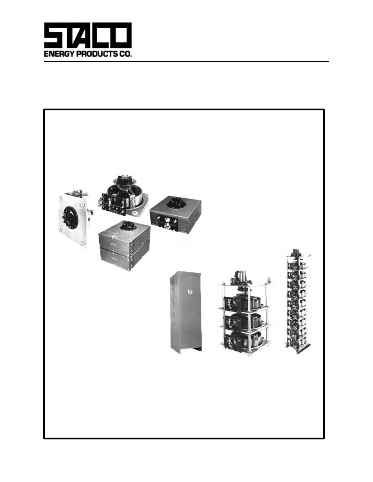
Variable Transformers
ll
Series 5000
28.0 to 252.0 Amperes
Page 2
5000 Series
The 5011/5021 Series Variable transformers are designed to
control large KVA requirements. The 5011 operates on 120
volts and is rated for constant current of 50 amperes. The 5021
operates on 240 volts and constant current of 28 amperes. The
5011 Series units have coil tapping arrangements allowing output voltage from 0-117% of line voltage, while the 5021 Series
allows output voltage from 0 to line voltage or 17% above line
voltage. They can be operated at frequencies between 50 and
400 Hertz with a rating at higher than rated frequency.
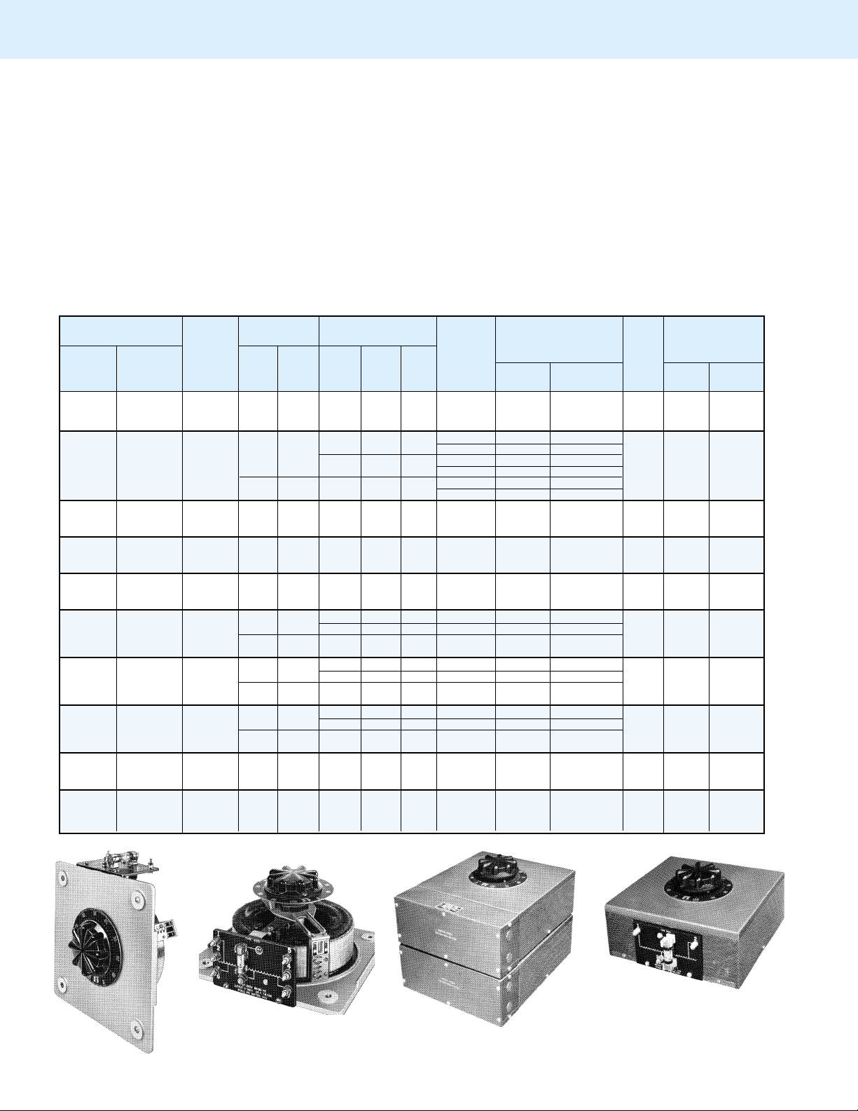
Adjustable shaft design on manually operated models permits
back-of-panel or bench mounting. Terminals are 1/4” screw
type. For single and two ganged units, case styles are available
in either “C”style, which encloses only the coil, or the “CT”style,
P AR T NUMBER INPUT OUTPUT SHAFT TERMINAL CONNECTIONS NET WEIGHT
MANUALLY MOTOR
OPERA TED DRIVEN AMPS KVA INCREASE INPUT OUTPUT
5011 M5011
5011C M5011C
5011CT M5011CT
5021 M5021
5021C M5021C
5021CT M5021CT
5011-2D M5011-2D Three
5011C-2D M5011C-2D Phase 120 50/60 0-140 50 12.1 CW 2-1-2 3-1-3 20 & 5 134 155
5011CT-2D M5011CT-2D Open Delta
5011-2P M5011-2P Single
5011C-2P M5011C-2P Phase 120 50/60 0-140 100 14.0 CW 1-2 1-B 21 136 157
5011CT-2P M5011CT -2P Parallel
5011-2S M5011-2S Single
5011C-2S M5011C-2S Phase 240 50/60 0-280 50 14.0 CW 2-2 3-3 20 & 4 134 155
5011CT-2S M5011CT -2S Series
5021-2D M5021-2D Three 240 50/60
5021C-2D M5021C-2D Phase
5021CT-2D M5021CT-2D Open Delta 120 50/60 0-280
5021-2P M5021-2P Single 240 50/60
5021C-2P M5021C-2P Phase
5021CT-2P M5021CT -2P Parallel 120 50/60 0-280
5021-2S M5021-2S Single 480 50/60
5021C-2S M5021C-2S Phase
5021CT-2S M5021CT -2S Series
5011-3P M5011-3P
5011E-3P M5011E-3P
5011-3Y M5011-3Y
5011E-3Y M5011E-3Y
WIRING
Single
Phase
Single
Phase CCW 4-1 4-3
Single
Phase 120 50/60 0-140 150 21.0 CW 1-2 1-D 22 216 237
Parallel
Three
Phase 240 60 0-280 50 24.2 CW 2-2-2 3-3-3 20 & 6 212 233
Wye
VOLTS HERTZ VOLTS
120 50/60 0-140 50 7.0 CW 1-2 1-3 18 57 78
240 50/60
120 50/60 0-280
240 50/60 0-560
0-240 28 6.7
0-280 28 7.8
0-240 28 11.6 CW 4-1-4 3-1-3
0-280 28 13.6 CW 2-1-2 3-1-3
0-240 56 13.4 CW 1-4 1-B
0-280 56 15.7 CW 1-2 1-B
0-480 28 13.5 CW 4-4 3-3
0-560 28 15.7 CW 2-2 3-3
MAX MAX VOLTAGE MA TIC
28*-12
VD CCW 4-7 4-3
28*-12
V.D.
56*-24
V.D.
28*-12
V.D.
which provides protective housing for both the coil and terminal
board. Knockouts are provided in the terminal board housing to
accomodate conduit or cable connections. For three ganged
and above, we offer our Nema 1, dripproof, fully front accessible “E” enclosure.
Motor-driven models are available from single thru 27 ganged
assemblies; cased or uncased (identified with the prefix “M” in
the part number). The synchronous motor is designed for
operation on 120 volt, 50/60 Hertz, single phase lines and
draws approximately 0.3 amperes. To meet a wide range of
application requirements, standard motor speeds of 5, 15, 30
and 60 seconds are available depending upon the size of the
variable transformer.
ROTATION For Increasing Voltage IN LBS.
FOR As Vie wed fr om Rotor End SCHE- (MAX)
MAN- MOTOR
UAL DRIVEN
19 57 78
21 136 157
CW 2-4 2-3
CCW 4-2 4-3
CW 2-5 2-3
3.4‡
5.8‡
6.8‡ CW 1-5 1-B
6.8‡ CW 5-5 3-3
CW 2-6 2-3
CW 5-1-5 3-1-3
(Pg 8 & 9)
20 & 5 134 155
20 & 4 134 155
5011
5021
5011C
5021CT-2
Page 3
5000 Series
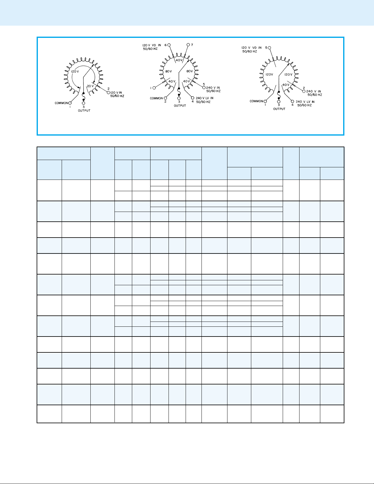
VIEW FROM ROTOR END
5011 5021 Single Unit 5021 Ganged Unit
For opposite rotation interchange external
connections from 5 to 1, 2 to 4 and 6 to 7.
P AR T NUMBER INPUT OUTPUT SHAFT TERMINAL CONNECTIONS NET WEIGHT
MANUALLY MOTOR
OPERA TED DRIVEN AMPS KVA INCREASE INPUT OUTPUT
5021-3P M5021-3P
5021E-3P M5021E-3P
5021-3Y M5021-3Y
5021E-3Y M5021E-3Y
5011-4D M5011-4D
5011E-4D M5011E-4D
5011-4P M5011-4P
5011E-4P M5011E-4P
WIRING
Single 240 50/60
Phase
Parallel
Three 480
Phase
VOLTS HERTZ VOLTS
0-240 84 20.2 CW 1-4 1-D
0-280 84 23.5 CW 1-2 1-D
120 50/60 0-280
50/60 0-480 28 23..3 CW 4-4-4 3-3-3
60 0-560 28 27.2 CW 2-2-2 3-3-3
Wye 240 60 0-560
MAX MAX VOLTAGE MA TIC
84*-36 10.2‡
V. D.
28*-12
V. D.
Three
Phase 120 50/60 0-140 100 24.2 CW 2-1-2 B-1-B 21 & 5 314 335
Open Delta
Single
Phase 120 50/60 0-140 200 28.0 CW 1-2 1-D 22 316 337
Parallel
ROTATION For Increasing Voltage IN LBS.
FOR As Vie wed fr om Rotor End SCHE- (MAX)
(Pg 8 & 9)
22 216 237
CW 1-5 1-D
20 & 6 212 233
11.8‡ CW 5-5-5 3-3-3
MAN- MOTOR
UAL DRIVEN
Single
5011-4PS M5011-4PS Phase
5011E-4PS M5011E-4PS Series
240 50/60 0-280 100 28.0 CW 2-2 B-B 21 & 4 314 335
Parallel
5021-4D M5021-4D
5021E-4D M5021E-4D
5021-4P M5021-4P
5021E-4P M5021E-4P
5021-4PS M5021-4PS
5021E-4PS M5021E-PS
5011-5P M5011-5P
5011E-5P M5011E-5P
5011-6D M5011-6D
5011E-6D M5011E-6D
5011-6P M5011-6P
5011E-6P M5011E-6P
Three 240 50/60
Phase
Open Delta 120 50/60 0-280
Single 240 50/60
Phase
Parallel 120 50/60 0-280
Single 480 50/60
Phase
Series 240 50/60 0-560
Single
Phase 120 50/60 0-140 250 35.0 CW 1-2 1-D 22 400 420
Parallel
Three
Phase 120 50/60 0-140 150 36.4 CW 2-1-2 D-1-D 22 & 5 481 502
Open Delta
Single
Phase 120 50/60 0-140 300 42.0 CW 1-2 1-D 22 483 504
Parallel
0-240 56 23.3 CW 4-1-4 B-1-B
0-280 56 27.2 CW 2-1-2 B-1-B
56*-24
11.8‡ CW 5-1-5 B-1-B
V. D.
0-240 112 26.9 CW 1-4 1-D
0-280 112 31.4 CW 1-2 1-D
112*-48
V.D.
13.5‡
CW 1-5 1-D
0-480 56 26.9 CW 4-4 B-B
0-560 56 31.4 CW 2-2 B-B
56*-24
13.5‡ CW 5-5 B-B
V. D.
21 & 5 314 335
22 316 337
21 & 4 314 335
Single
5011-6PS M5011-6PS Phase
5011E-6PS M5011E-6PS Series
240 50/60 0-280 150 42.0 CW 2-2 D-D 22 & 4 481 502
Parallel
5011-6Y M5011-6Y
5011E-6Y M5011E-6Y
Three
Phase 240 60 0-280 100 48.5 CW 2-2-2 B-B-B 21 & 6 479 500
Wye
Page 4

5000 Series
P AR T NUMBER INPUT OUTPUT SHAFT TERMINAL CONNECTIONS NET WEIGHT
MANUALLY MOTOR VOLTS HERTZ VOLTS MAX MAX VOL TAGE MATIC
OPERA TED DRIVEN AMPS KVA INCREASE INPUT OUTPUT
5021-6D M5021-6D
5021E-6D M5021E-6D
5021-6P M5021-6P
5021E-6P M5021E-6P
5021-6PS M5021-6PS Phase 0-560 84 47.0 CW 2-2 D-D
5021E-6PS M5021E-6PS Series
5021-6Y M5021-6Y
5021E-6Y M5021E-6Y
5011-7P M5011-7P
5011E-7P M5011E-7P
5021-7P M5021-7P
5021E-7P M5021E-7P
5011-8D M5011-8D
5011E-8D M5011E-8D
5011-8P M5011-8P
5011E-8P M5011E-8P
5011-8PS M5011-8PS Phase
5011E-8PS M5011E-8PS Series
5021-8D M5021-8D
5021E-8D M5021E-8D
5021-8P M5021-8P
5021E-8P M5021E-8P
5021-8PS M5021-8PS Phase 0-560 112 62.7 CW 2-2 D-D
5021E-8PS M5021E-8PS Series
5011-9P M5011-9P
5011E-9P M5011E-9P
5011-9Y M5011-9Y
5011E-9Y M5011E-9Y
5021-9P M5021-9P
5021E-9P M5021E-9P
5021-9Y M5021-9Y
5021E-9Y M5021E-9Y
M5011-10D
—
M5011E-10D
M5011-10PS Phase
—
M5011E-10PS Series
M5021-10D
—
M5021E-10D
WIRING FOR As Vie wed fr om Rotor End SCHE- (MAX)
Three 240 50/60
Phase
Open Delta 120 50/60 0-280
Single 240 50/60
Phase
Parallel 120 50/60 0-280
Single
Parallel V.D.
Three 480
Phase
Wye 240 60 0-560
Single
Phase 120 50/60 0-140 350 49.0 CW 1-2 1-D 22 563 584
Parallel
Single 240 50/60
Phase
Parallel 120 50/60 0-280
Three
Phase 120 50/60 0-140 200 48.4 CW 2-1-2 D-1-D 22 & 5 640 661
Open Delta
Single
Phase 120 50/60 0-140 400 56.0 CW 1-2 1-D 22 642 663
Parallel
Single
Parallel
Three 240 50/60
Phase
Open Delta 120 50/60 0-280
Single 240 50/60
Phase
Parallel 120 50/60 0-280
Single
Parallel V.D.
Single
Phase 120 50/60 0-140 450 63.0 CW 1-2 1-D 22 721 742
Parallel
Three
Phase 240 60 0-280 150 72.5 CW 2-2-2 D-D-D 22 & 6 717 738
Wye
Single 240 50/60
Phase
Parallel 120 50/60 0-280
Three 480
Phase
Wye 240 60 0-560
Three
Phase 120 50/60 0-140 250 60.6 CW 2-1-2 D-1-D 22 & 5 812
Open Delta
Single
Parallel
Three 240 50/60
Phase
Open Delta 120 50/60 0-280
480 50/60
240 50/60 0-560
240 50/60 0-280 200 56.0 CW 2-2 D-D 22 & 4 640 661
480 50/60
240 50/60 0-560
240 50/60 0-280 250 70.0 CW 2-2 D-D 22 & 4 812
0-240 84 34.9 CW 4-1-4 D-1-D
0-280 84 40.7 CW 2-1-2 D-1-D
84*-36
V. D.
0-240 168 40.3 CW 1-4 1-D
0-280 168 47.0 CW 1-2 1-D
168*-72
V. D.
0-480 84 40.3 CW 4-4 D-D
84*-36
50/60 0-480 56 46.6 CW 4-4-4 B-B-B
60 0-560 56 54.3 CW 2-2-2 B-B-B
50/60 0-480 84 69.8 CW 4-4-4 D-D-D
60 0-560 84 81.5 CW 2-2-2 D-D-D
56*-24
V. D.
0-240 196 47.0 CW 1-4 1-D
0-280 196 54.9 CW 1-2 1-D
196*-84
V. D.
0-240 112 46.6 CW 4-1-4 D-1-D
0-280 112 54.3 CW 2-1-2 D-1-D
112*-48
V. D.
0-240 224 53.8 CW 1-4 1-D
0-280 224 62.7 CW 1-2 1-D
224*-96
V. D.
0-480 112 53.8 CW 4-4 D-D
112*-48
0-240 252 60.5 CW 1-4 1-D
0-280 252 70.6 CW 1-2 1-D
252*-108
V. D.
84*-36
V. D.
0-240 140 58.2 CW 4-1-4 D-1-D
0-280 140 67.9 CW 2-1-2 D-1-D
140*-60
V. D.
ROTATION For Increasing Voltage IN LBS.
(Pg 8 & 9)
17.6‡ CW 5-1-5 D-1-D
20.4‡ CW 1-5 1-D
20.4‡ CW 5-5 D-D
23.5‡
23.5‡ CW 1-5 1-D
23.3‡ CW 5-1-5 D-1-D
26.9‡ CW 1-5 1-D
26.9‡ CW 5-5 D-D
30.2‡ CW 1-5 1-D
35.0‡ CW 5-5-5 D-D-D
29.1‡ CW 5-1-5 D-1-D
CW 5-5-5 B-B-B
22 & 5 481 502
22 483 504
22 & 4 481 502
21 & 6 479 500
22 563 584
22 & 5 640 661
22 642 663
22 & 4 640 742
22 721 742
22 & 6 717 738
22 & 5 812
MAN- MOTOR
UAL DRIVEN
Page 5

5000 Series
P AR T NUMBER INPUT OUTPUT SHAFT TERMINAL CONNECTIONS NET WEIGHT
MANUALLY MOTOR VOLTS HERTZ VOLTS MAX MAX VOL TAGE MATIC
OPERA TED DRIVEN AMPS KVA INCREASE INPUT OUTPUT
M5021-10PS Phase 0-560 140 78.4 CW 2-2 D-D
—
M5021E-10PS Series
M5011-12D
—
M5011E-12D
M5011-12PS Phase
—
M5011E-12PS Series
M5021-12D
—
M5021E-12D
M5021-12PS Phase 0-560 168 94.1 CW 2-2 D-D
—
M5021E-12PS Series
M5011-14D
—
M5011E-14D
M5011-14PS Phase
—
M5011E-14PS Series
M5021-14D
—
M5021E-14D
M5021-14PS Phase 0-560 196 109.8 CW 2-2 D-D
—
M5021E-14PS Series
M5011-16D
—
M5011E-16D
M5011-16PS Phase
—
M5011E-16PS Series
M5021-16D Phase 0-280 224 108.6 CW 2-1-2 D-1-D
—
M5021E-16D Open Delta
M5021-16PS Phase 0-560 224 125.5 CW 2-2 D-D
—
M5021E-16PS Series
M5011-18D
—
M5011E-18D
M5011-18PS Phase
—
M5011E-18PS Series
M5021-18D
—
M5021E-18D
M5021-18PS Phase 0-560 252 141.0 CW 2-2 D-D
—
M5021E-18PS Series
M5011-12Y
—
M5011E-12Y
M5021-12Y
—
M5021E-12Y
WIRING FOR As Vie wed fr om Rotor End SCHE- (MAX)
Single
Parallel V.D.
Three
Phase 120 50/60 0-140 300 72.7 CW 2-1-2 D-1-D 22 & 5 — 940
Open Delta
Single
Parallel
Three 240 50/60
Phase
Open Delta 120 50/60 0-280
Single
Parallel V.D.
Three
Phase 120 50/60 0-140 350 84.9 CW 2-1-2 D-1-D 22 & 5 — 1097
Open Delta
Single
Parallel
Three 240 50/60
Phase
Open Delta 120 50/60 0-280
Single
Parallel V.D.
Three
Phase 120 50/60 0-140 400 96.7 CW 2-1-2 D-1-D 22 & 5 — 1254
Open Delta
Single
Parallel
Three
Single
Parallel V.D.
Three
Phase 120 50/60 0-140 450 109.0 CW 2-1-2 D-1-D 22 & 5 — 1417
Open Delta
Single
Parallel
Three 240 50/60
Phase
Open Delta
Single
Parallel V.D.
Three
Phase 240 60 0-280 200 96.7 CW 2-2-2 D-D-D 22 & 6 — 942
Wye
Three 480
Phase
Wye 240 60 0-560
480 50/60
240 50/60 0-560
240 50/60 0-280 300 84.0 CW 2-2 D-D 22 & 4 — 940
480 50/60
240 50/60 0-560
240 50/60 0-280 350 98.0 CW 2-2 D-D 22 & 4 — 1097
480 50/60
240 50/60 0-560
240 50/60 0-280 400 112.0 CW 2-2 D-D 22 & 4 — 1254
240 50/60
120 50/60 0-280
480 50/60
240 50/60 0-560
240 50/60 0-280 450 126.0 CW 2-2 D-D 22 & 4 — 1417
120 50/60 0-280
480 50/60
240 50/60 0-560
0-480 140 67.2 CW 4-4 D-D
140*-60
0-240 168 69.8 CW 4-1-4 D-1-D
0-280 168 81.5 CW 2-1-2 D-1-D
168*-72
V. D.
0-480 168 80.6 CW 4-4 D-D
168*-72
0-240 196 81.5 CW 4-1-4 D-1-D
0-280 196 95.1 CW 2-1-2 D-1-D
196*-84
V. D.
0-480 196 94.1 CW 4-4 D-D
196*-84
0-240 224 93.1 CW 4-1-4 D-1-D
224*-96
V. D.
0-480 224 107.5 CW 4-4 D-D
224*-96
0-240 252 104.5 CW 4-1-4 D-1-D
0-280 252 122.2 CW 2-1-2 D-1-D
252*-108
V. D.
0-480 252 121.0 CW 4-4 D-D
252*-108
50/60 0-480 112 93.1 CW 4-4-4 D-D-D
60 0-560 112 108.6 CW 2-2-2 D-D-D
112*-48
V. D.
ROTATION For Increasing Voltage IN LBS.
(Pg 8 & 9)
33.6‡ CW 5-5 D-D
34.9‡ CW 5-1-5 D-1-D
40.3‡ CW 5-5 D-D
40.8‡ CW 5-1-5 D-1-D
47.1‡ CW 5-5 D-D
46.6‡ CW 5-1-5 D-1-D
53.8‡
52.5‡ CW 5-1-5 D-1-D
60.5‡ CW 5-5 D-D
46.6‡ CW 5-5-5 D-D-D
CW 5-5 D-D
22 & 4 — 812
22 & 5 — 940
22 & 4 — 940
22 & 5 — 1097
22 & 4 — 1097
22 & 5 — 1254
22 & 4 — 1254
22 & 5 — 1417
22 & 4 — 1417
22 & 6 — 942
MAN- MOTOR
UAL DRIVEN
Page 6

5000 Series
P AR T NUMBER INPUT OUTPUT SHAFT TERMINAL CONNECTIONS NET WEIGHT
MANUALLY MOTOR VOLTS HERTZ VOLTS MAX MAX VOL TAGE MATIC
OPERA TED DRIVEN AMPS KVA INCREASE INPUT OUTPUT
M
—
—
—
—
—
—
—
—
—
—
5011-15Y
M5011E-15Y
M5021-15Y
M5021E-15Y
M5011-18Y
M5011E-18Y
M5021-18Y
M5021E-18Y
M5011-21Y
M5011E-21Y
M5021-21Y
M5021E-21Y
M5011-24Y
M5011E-24Y
M5021-24Y
M5021E-24Y
M5011-27Y
M5011E-27Y
M5021-27Y
M5021E-27Y
WIRING FOR As Vie wed fr om Rotor End SCHE- (MAX)
Three
Phase 240 60 0-280 250 121.0 CW 2-2-2 D-D-D 22 & 6 — 1179
Wye
Three 480
Phase
Wye 240 60 0-560
Three
Phase 240 60 0-280 300 145.5 CW 2-2-2 D-D-D 22 & 6 — 1415
Wye
Three 480
Phase
Wye 240 60 0-560
Three
Phase 240 60 0-280 350 169.5 CW 2-2-2 D-D-D 22 & 6 — 1654
Wye
Three 480
Phase
Wye 240 60 0-560
Three
Phase 240 60 0-280 400 193.7 CW 2-2-2 D-D-D 22 & 5 — 1892
Wye
Three 480
Phase
Wye 240 60 0-560
Three
Phase 240 60 0-280 450 218.4 CW 2-2-2 D-D-D 22 & 6 — 2131
Wye
Three 480
Phase
Wye 240 60 0-560
50/60 0-480 140 116.5 CW 4-4-4 D-D-D
60 0-560 140 136.0 CW 2-2-2 D-D-D
140*-60
V. D.
50/60 0-480 168 139.5 CW 4-4-4 D-D-D
60 0-560 168 163.3 CW 2-2-2 D-D-D
168*-72
V. D.
50/60 0-480 196 163.0 CW 4-4-4 D-D-D
60 0-560 196 189.5 CW 2-2-2 D-D-D
196*-84
V. D.
50/60 0-480 224 186.5 CW 4-4-4 D-D-D
60 0-560 224 217.8 CW 2-2-2 D-D-D
224*-96
V. D.
50/60 0-480 252 209.5 CW 4-4-4 D-D-D
60 0-560 252 244.0 CW 2-2-2 D-D-D
252*-108
V. D.
ROTATION For Increasing Voltage IN LBS.
(Pg 8 & 9)
22 & 6 — 1179
58.2‡ CW 5-5-5 D-D-D
22 & 6 — 1415
70.0‡ CW 5-5-5 D-D-D
22 & 6 — 1654
82.0‡ CW 5-5-5 D-D-D
22 & 6 — 1892
93.0‡ CW 5-5-5 D-D-D
22 & 6 — 2131
105.0‡ CW 5-5-5 D-D-D
MAN- MOTOR
UAL DRIVEN
* Maximum output current in output voltage range from 0 to 25 percent above line voltage. At higher output voltages, output current must be reduced according
to rating curve, Figure B, page 6.
‡ Maximum KVA at maximum output and corresponding de-rated current. Maximum KVA at lower output voltages may be calculated from derating curve. Figure
B, page 6.
V.D. Voltage Doubler
5000/6000 Series
Enclosed Unit
30M6020-9Y
30M5011-3Y
Page 7

5000/6000 Series
Manual Single, Uncased
Two Ganged Three Ganged
A 17.06” [433.3] 23.12” [587.4]
B 13.56” [344.4] 19.62” [498.3]
C 15.12” [384.2] 21.19” [538.2]
Manual Single, Cased
Manual Tw o-Ganged, Cased
Manual Tw o and Three-Ganged, Uncased
Single Unit Two Ganged
A 12.94” [328.6] 19.18” [487.3]
B 15.50” [393.7] 21.56” [547.6]
A
B
C (5 sec.) 13.53” [343.7] 19.62” [498.5] 25.75” [654.0]
C (15, 30 & 60 sec.) 15.12” [384.2] 21.19” [538.2] 27.25” [692.0]
Single Unit Two Ganged Three Ganged
13.25” [336.6] 19.32” [490.7] 25.38”[644.5]
9.75” [247.7] 15.82”[401.8] 21.88”[555.7]
Motor Driven, Single,Two and Three-Ganged, Uncased
Motor Driven, Single and Two-Ganged, Cased
Page 8

5000/6000 Series
3 Ganged 4, 5, 6 Ganged 7, 8, 9 Ganged
A
35.8” [909.32] 54.8” [1391.9] 72.8” [1849.1]
Manual Three to Nine-Ganged, Cased
AB
4 Ganged 30.38” [771.5] 27.38” [695.3]
5 Ganged 36.44” [925.5] 33.44” [849.3]
6 Ganged 42.50” [1079.5] 39.50” [1003.3]
7 Ganged 48.56” [1233.5] 45.56” [1157.3]
8 Ganged 54.62” [1387.5] 51.62” [1311.3]
9 Ganged 60.69” [1541.5] 57.69” [1465.3]
3 Ganged 4, 5,6 Ganged 7,8, 9 Ganged
A
33.5” [850.9] 52.5” [1333.5] 70.5” [1061.9]
Motor-Driven Three to Nine-Ganged, Cased
10 & 12 Ganged 14, 16 & 18 Ganged
A
52.5” [1333.5] 70.5” [1790.7]
Motor-Driven 10, 12, 14, 16 & 18-Ganged Open Delta and Parallel,
Cased
Manual Four to Nine-Ganged, Uncased
5021-3Y
Page 9

5000/6000 Series
12 Ganged 15 Ganged 18 Ganged 21 Ganged 24 Ganged 27 Ganged
A
36.31” [922.3] 42.38” [1076.4] 48.44” [1230.3] 54.50” [1384.3] 60.56” [1538.3] 66.62” [1692.3]
B
30.94” [786.8] 37.00”[939.8] 43.06” [1093.8] 49.12” [1247.8] 55.19” [1401.8] 61.25” [1555.8]
Motor-Driven 12, 15, 18, 21, 24 & 27-Ganged, Uncased
12, 15,18 Ganged 21, 24,27 Ganged
A
52.5” [1333.5] 70.5” [1790.7]
Motor-Driven 12, 15, 18, 21, 24 & 27-Ganged, Cased
10 Ganged 12 Ganged 14 Ganged 16 Ganged 18 Ganged
A
42.38” [1076.3] 48.44” [1230.3] 54.50”[1384.3] 60.56” [1538.3] 66.62” [1692.3]
B
37.00” [939.8] 43.06” [1093.8] 49.12” [1247.8] 55.19” [1401.8] 61.25” [1555.8]
Motor-Driven 10, 12, 14, 16 & 18-Ganged Open Delta
& Parallel, Uncased
60M5021-27Y
 Loading...