

Page 1
High-Current DC Loads
4700 LXI SERIES
K 120V, 1kW/200A to 36kW/7200A
K 18 Voltage, Current, Power and
Timing Measurements
K Complex load profile playback
K Air cooling
K Touch-panel manual control
APPLICATION
4700 LXI Series Electronic Loads are designed for testing applications that require high-power and high-current
plus measurement of UUT dynamic performance. The Loads provide exceptional reliability combined with the
inherent simplicity and safety of air cooling. The 4700 Loads are controlled through either a manual touch-panel, a
LabVIEW soft-panel or an emPower™ Test Executive enabled automatic test station. Typical power conversion
products to be tested include higher-power DC supplies, telecom rectifiers, fuel cells and batteries.
EXTENDED INTERNAL MEASUREMENTS
The 4700 Loads eliminate the need for separate external
instruments and related switching to capture timing and other
dynamic measurements during UUT turn-on and turn-off. This
is accomplished by incorporating the task-essential features of
a DMM, DSO and Transient Generator. With this built-in
capability, the 4700 can rapidly generate engineeringcharacterization-like test information at faster test speeds with
the additional benefit of cost savings from fewer measurement
instruments, switches and interconnection wiring.
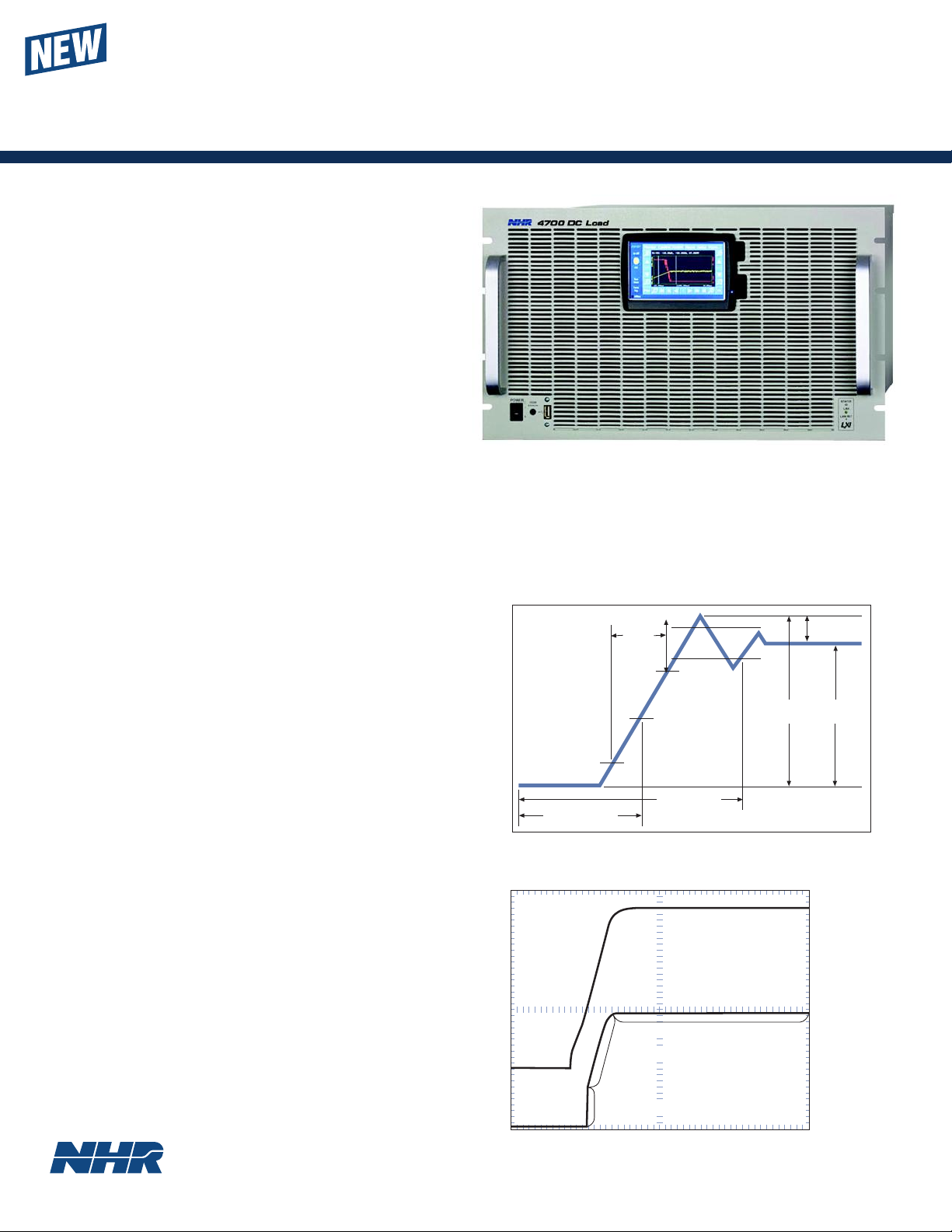
AUTO MODE
The 4700 contains a unique Auto Mode that provides
glitchless automatic switching between CR, CC, CV and CP
limits. Previously challenging tests that are now made
possible include turn-on into a CR load, confirming the
complete V-I curve for Lithium-Ion battery chargers, and
preventing device-under-test blowup should a protection
circuit fail.
Rise
Time
Settle Time
Turn-on Time
max
min
Peak Settle
Turn-on voltage & current measurements
Constant Current
Voltage
Constant Resistance
Overshoot
Current
Constant Voltage
Power supply turn-on voltage & current
waveforms in Auto Mode
Page 2
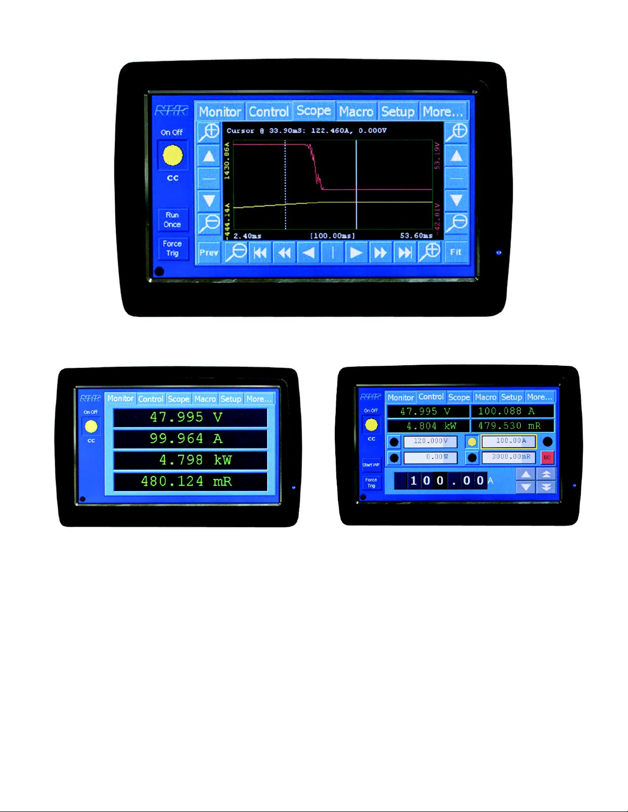
Just as touch-panels have revolutionized the user
interface on mobile phones and GPS navigation
devices, they now are about to change electronic
power instruments. The old paradigm of controlling
electronic loads through knobs, meters and keypads
has been lacking for years. There are just too many
control & display functions to manage, especially
with the latest generation of smart loads that contain
digitized measurements for oscilloscope-like
waveform displays.
The new NHR PowerTouch panel eliminates those
limitations forever. The display is organized through
POWERTOUCH MANUAL CONTROL
Monitor Tab
Control tab
6 tabs, each providing a full screen with complete
control & display of related information. For instance,
a Monitor tab displays actual measurements either in
the local or remote-control mode. A Control tab
provides for setting voltage, current, resistance and
power as well as the CC, CV, CR and CP Operating
Modes. The unique Scope tab provides the ability to
zoom in on specific areas of interest as well as take
basic measurements on waveform captures. Those
waveform captures can then be saved on a SD card for
later review on a PC. Load user interfaces have never
been as comprehensive or easier to use as is now
possible with this touch-panel technology.
Scope Tab
Actual Size
Page 3

MODEL 4700 LXI DC LOADS
COMPLEX LOAD PROFILE PLAYBACK
To facilitate ease of re-creating complex, precisely
timed, multi-mode load profiles, a 100-step macrorecording capability allows capturing a dynamic
sequence for later playback from within the Load.
Additional complex profiles can be stored in a system
controller library to be downloaded to the Load when
required.
FAULT TOLERANT
The 4700 Loads are designed to keep running under
just about any condition, even certain internal
component failures. Standard for this class of
instrument is protection against output over-voltage,
over-current, over-power, reverse-voltage, and internal
over-temperature. In addition, controller intelligence
continuously monitors sub-circuit performance and
redistributes the current load as necessary. This fault
tolerant technique allows the user to continue testing
with proper warning of a fault condition. Further load
reliability is assured through extensive startup self-test
and real-time monitoring.
FIELD EXPANDABLE
Because the 4700 Loads are modular, synchronously
controlled and actively power-balanced, they operate
efficiently in parallel as a single load. In this manner the
Loads are field expandable with changes only to the
input connections. This feature allows selection of only
what is currently needed with confidence that future
higher power requirements can be accommodated with
minimum disruption and cost.
100.0 V10.0 V1.0 V0.1 V
1kW
2kW
3kW
6kW
VOLTS
12kW
18kW
24kW
36kW
PANEL OVERVIEW
1. Power Switch
2. Hardware error indicator
3. USB connector
4. Touch panel display
5. LXI status indicators
6. COMM In/Out connectors
7. RS232 connector
8. Trig In/Out connectors
9. DIN/DOUT connector
10. Address switch
11. Sync In/Out connectors
12. OVPS connector
1 A 10 A 100 A 1,000 A
AMPS
Constant Power operating envelopes
13. Remote sense connector
14. I Range switch
15. Enable indicator
16. I Control connector
17. I Monitor connector
18. Load connections
19. Network connectors
20. Parallel switch
21. Voltage select switch
22. Chassis GND stud
23. AC input connector
24. Parallel connectors
10,000 A
Page 4

1
Specifications apply at 23o+/- 5oC after a 10 minute warm up.
2
Accuracies apply when Settings and/or Measurements >10% of Range.
3
Current linearly reduced between 1 and 0.15 V.
4
Models 2 - 36 kW also have a 20 A /1 KW Range with reduced accuracy.
5
Set 1000% to 6000% of Range = 10% Accuracy.
6
Single channel capture. Simultaneous Voltage and Current captures would halve sample
rate and memory available.
SPECIFICATIONS
1
4700 Ratings 4700-1 4700-2 4700-3 4700-6 4700-12 4700-18 4700-24 4700-36
Power 1 kW 2 kW 3 kW 6 kW 12 kW 18 kW 24 kW 36 kW
Maximum Current
2
200 A 400 A 600 A 1200 A 2400 A 3600 A 4800 A 7200 A
Voltage Range
3
1-120 V 1-120 V 1-120 V 1-120 V 1-120 V 1-120 V 1-120 V 1-120 V
Programmable Modes Accuracies: % of Set + % of Range, Resolution: % of Range
Constant Current
Ranges
4
20, 200 A 40, 400 A 60, 600 A 120, 1200 A 240, 1200 A 360, 3600A 480, 4800 A 720, 7200 A
Accuracy 0.12%+0.08% 0.12%+0.08% 0.12%+0.08% 0.12%+0.08% 0.12%+0.08% 0.12%+0.08% 0.12%+0.08% 0.12%+0.08%
Resolution 0.025% 0.025% 0.025% 0.025% 0.025% 0.025% 0.025% 0.025%
Constant Voltage
Ranges
6.6, 20, 66, 120 V 6.6, 20, 66, 120 V 6.6, 20, 66,120 V 6.6, 20, 66,120 V 6.6, 20, 66, 120 V 6.6, 20, 66,120 V 6.6, 20, 66, 120 V
6.6, 20, 66, 120 V
Accuracy 0.05%+0.05% 0.05%+0.05% 0.05%+0.05% 0.05%+0.05% 0.05%+0.05% 0.05%+0.05% 0.05%+0.05% 0.05%+0.05%
Resolution 0.025% 0.025% 0.025% 0.025% 0.025% 0.025% 0.025% 0.025%
Constant Power
Range 0 - 1 kW 0 - 2 kW 0 - 3 kW 0 - 6 kW 0 - 12 kW 0 - 18 kW 0 - 24 kW 0 - 36 kW
Accuracy 1% + 1% 1% + 1% 1% + 1% 1% + 1% 1% + 1% 1% + 1% 1% + 1% 1% + 1%
Resolution 0.025% 0.025% 0.025% 0.025% 0.025% 0.025% 0.025% 0.025%
Constant Resistance
Range 5 m
- 180 2.5 m - 90 1.67 m - 60 833 µ - 30 417 µ - 15 278 µ - 10 208 µ -7.5 136 µ - 5
Accuracy
5
2% 2% 2% 2% 2% 2% 2% 2%
Slew Rate (10 - 90%)
Range 1 A/s - 20 A/µs 2 A/s - 40 A/µs 3 A/s - 60 A/µs 6 A/s - 120 A/µs 12 A/s - 240 A/µs 18 A/s - 360 A/µs 24 A/s - 480 A/µs 36 A/s - 720 A/µs
Rise Time 10 µs - 20 s 10 µs - 20 s 10 µs - 20 s 10 µs - 20 s 10 µs - 20 s 10µs - 20 s 10µs - 20 s 10 µs - 20 s
Resolution < 5 µs < 5 µs < 5 µs < 5 µs < 5 µs < 5 µs < 5 µs < 5 µs
Accuracy 1% +/- 5µs 1% +/- 5µs 1% +/- 5µs 1% +/- 5µs 1% +/- 5µs 1% +/- 5µs 1% +/- 5µs 1% +/- 5µs
Short Circuit
Resistance 50, 5 m
25, 2.5 m
17, 1.7 m
8.3 m- 833 µ 4.17 m- 417 µ2.78 m- 278 µ2.08 m- 208 µ1.39 m- 139 µ
Current Max 33, 333 A 67, 667 A 60, 608 A 120, 1200 A 240, 2400 A 360, 3600 A 480, 4800 A 720, 7200 A
Macro
Modes Any single Mode
Repetition Single Burst or Continuous
Settings 100
Period 40 µs - 20 s
Delay 20 µs - 20 s
Resolution 10 µs
Accuracy 1% +/- 5 µs
Measurements Accuracies: % of Measurement + % of Range, Resolution: % of Range
Current
Ranges 20, 200 A 40, 400 A 60, 600 A 120, 1200 A 240, 2400 A 360, 3600 A 480, 4800 A 720, 7200 A
Accuracy 0.12%+0.06% 0.12%+0.06% 0.12%+0.06% 0.12%+0.06% 0.12%+0.06% 0.12%+0.06% 0.12%+0.06% 0.12%+0.06%
Resolution 0.0015% 0.0015% 0.0015% 0.0015% 0.0015% 0.0015% 0.0015% 0.0015%
DC Voltage
Ranges 6.6, 66, 166 V 6.6, 66, 166 V 6.6, 66, 166 V 6.6, 66, 166 V 6.6, 66, 166 V 6.6, 66, 166 V 6.6, 66, 166 V 6.6, 66, 166 V
Accuracy 0.01%+0.02% 0.01%+0.02% 0.01%+0.02% 0.01%+0.02% 0.01%+0.02% 0.01%+0.02% 0.01%+0.02% 0.01%+0.02%
Resolution 0.0015% 0.0015% 0.0015% 0.0015% 0.0015% 0.0015% 0.0015% 0.0015%
Power
Ranges Current Range x Voltage Range
Accuracy Current Accuracy + Voltage Accuracy
Resolution 0.0015% Range
Waveform Capture
Bandwidth 25 kHz
Accuracy 1% R
Channels Voltage, Current or both MUX’d
Digitizing Rate
6
100 - 100K Samples/s
Memory 16K Samples
Timebase 10 µs - 8 s
Triggering System or External
Waveform Analysis Voltage, Current, Power, Overshoot, Undershoot, Rise/Fall Time, Turn-On Time, Settling Time, Hold-Up Time, AC RMS, AC+DC RMS
Control
User Interface PC soft panel or manual touch-panel
PC Required 3 GHz µP with 512 MB RAM, SVGA display, 80 GB HD
OS Windows XP, Vista
Test Executive NI LabVIEW, emPower™ with integrated datalog/test report support
Communications Ethernet (LXI), RS232, NHR RS485
Drivers Active X
Physical
Load Connectors Bus bars with lugs
Operating Temperature 0 - 40º C at full power and <75% duty cycle
Input Power 115/230 ± 10% VAC, 47 - 63 Hz
Dimensions (HxWxD) 5
1
/4 x 19 x 22 in 51/4 x 19 x 22 in 101/2 x 19 x 22 in 101/2 x 19 x 22 in 35 x 23 x 30 in 43 x 23 x 30 in 57 x 23 x 30 in 72 x 23 x 30 in
Weight 40 lbs 50 lbs 75 lbs 100 lbs 250 lbs 400 lbs 570 lbs 815 lbs
Additional Features
Remote Voltage Sense 2 VDC max drop between sense and load input
Self Test Power-up self test of all major functions including status of input, output, control and protection circuits
Performance Monitoring Continuous checking of performance parameters and appropriate error messages and/or LED fault indicators when necessary
Calibration Closed cover, all adjustments made in software and stored in EEPROM
Protection OP, OC, OV, OT, Reverse Voltage and Undervoltage Lockout
Trigger Output Synchronizes external device to programmed load step
Trigger Input Synchronizes programmed load step to an external device
Current Monitor 0 - 10 V external signal appropriate to 100% current for the selected range
Analog Control 0 -10 V external signal appropriate to 100% current for the selected range
Fan Noise Reduction Automatic fan speed control
NH Re search, Incorporated
16601 Hale Avenue, Irvine, California 92606
Tel: 949-474-3900 • Fax: 949-474-7062
E-mail: sales@nhresearch.com
©Copyright 2010, NH Research Incorporated.
All rights reserved. Specifications subject to
change without notice.
 Loading...