

Page 1
AC Electronic Loads
4600 SERIES
q 6 power levels: 3, 6, 12, 18, 24 & 36 kW
q CC, CR, CV, CP, SC, UPF and CNL emulation modes
q Programmable crest factor and power factor
q 12 high-accuracy, internal measurements
q User-defined waveforms
q 100-step Multi-Mode Macros
q PC softpanel with current, voltage and power
waveform display
q Single and 3-phase configuration options
q RS-232 and USB communication interfaces
Page 2
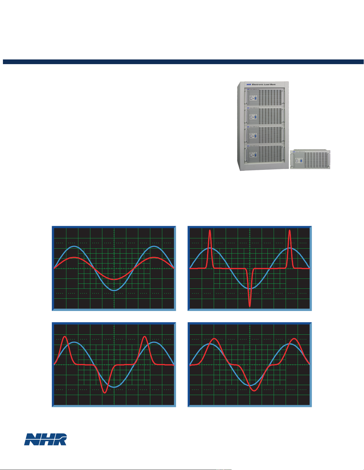
APPLICATION
4600 AC Loads are design for test applications that require linear and non-linear AC loading in several emulation
modes with power and crest factors control. This programmable versatility allows testing with a wide variety of
potential field operating conditions to assure unit-under-test (UUT) reliability. Products tested include
uninterruptible power supplies (UPS), AC sources, inverters, switches, circuit breakers, fuses and connectors.
EMULATION MODES
To provide testing under the broadest range of loading conditions, the 4600 Series offers 7 different emulation
modes. Constant Current (CC) mode provides current to be drawn constantly, making it suitable for non-linear,
linear and regulation loading. While Constant Resistance (CR) mode allows the load to emulate a power resistor,
Constant Voltage (CV) allows emulating a shunt regulator. Constant Power (CP) mode emulates a constant-power
load such as a switching power supply. The Short Circuit (SC) mode allows the load to test the UUT’s short
circuit protection capability. Unity Power Factor (UPF) mode causes power factor to be as close as possible to
unity, useful when the input voltage is non-sinusoidal. The new Complex Non-Linear Waveform (CNL) Mode
allows the user to define the waveform to prevent UUT current overstressing in the event of a voltage collapse.
These comprehensive capabilities provide the user almost every conceivable AC loading condition.
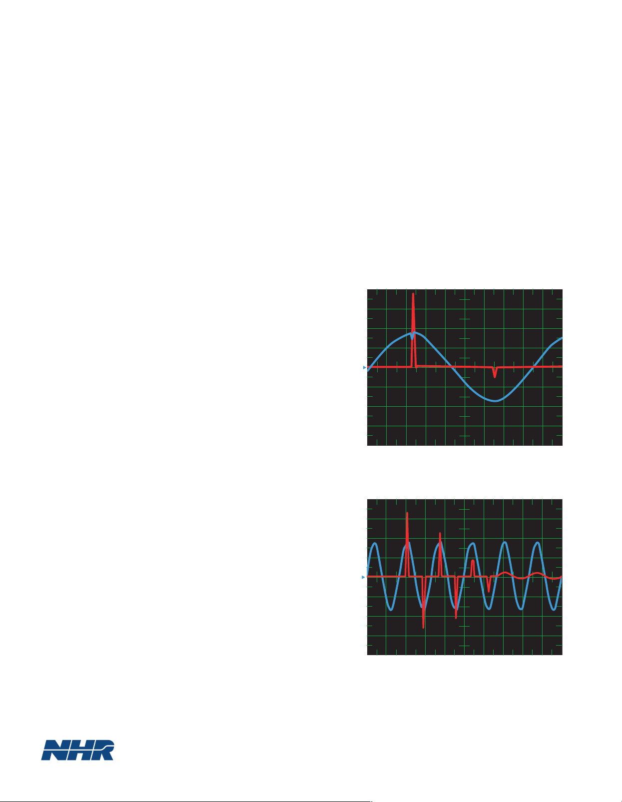
USER-DEFINED WAVEFORMS
The 4600 has the ability to control current through a userdefined waveform. The waveform is created by a powerful
graphical editor that facilitates starting with a straight line or
modifying a generated waveform based on current, power and
crest factor. The graphical editor includes an auto-check feature
to ensure the settings are compatible with each other and within
the capabilities of the load. It also supports waveform
smoothing, symmetrical and asymmetrical waveform creation.
With this editor, waveforms can be quickly created to duplicate
complex transient conditions. This would include adding
asymmetrical inflections, inserting transient anomalies such as
spikes and dropouts, and just about anything else that can be
drawn as a single-cycle waveform.
100-STEP MULTI-MODE MACROS
Macros are queues of up to 100 steps that can be triggered
locally, thereby providing very fast current, power and crest
factor changes, up to every cycle. Further, a Macro can be
executed as a single shot or looped.
User-Defined Asymetrical Current Waveshape
2.000 mS/div
Wf1, Chn 001, 100 V/div.
Wf2, Chn 002, 20 A/div
Start-Up Inrush Current Macro
em POWER LE TEST EXECUTIVE OPTION
The 4600 is supplied with software for a PC softpanel that
provides complete instrument control, measurement and
waveform display. Upgrading to a full test executive with
drivers for all NHR power instruments is also possible through
emPower LE, which adds a test sequencer, basic test routines,
and reporting.
10.000 mS/div
Wf1, Chn 001, 100 V/div.
Wf2, Chn 002, 20 A/div
Page 3

IGH ACCURACY MEASUREMENTS
H
he 4600 Series provides high-accuracy frequency, voltage, peak voltage, current, peak current, crest factor,
T
apparent power, true power, peak power, reactive power, power factor and resistance measurements by combining
high-resolution measurements with precision ranging. The ability to make measurements internally eliminates
multiple external measurement instruments plus associated signal matrixing. In this manner the 4600 provides for
a more compact, less costly and considerably faster test system.
WIDE RANGE OF POWER LEVELS
Operating Envelopes
The 4600 Series is now offered in 6 power levels between 3 and 36 kW.
Any unit can be field expandable in 3 kW increments to address future
higher power needs. Contact factory for loads higher than 36 kW.
GRAPHIC USER INTERFACE
A PC-hosted graphic user interface eclipses the traditional front panel
clutter of knobs, dials, keypads, and digital displays that are carry-over
from a time of test instrumentation with a far more limited set of
features. In addition to a more comprehensive presentation of operation,
measurement and status information, softpanel advantages include the
ability to program and recall Macros, editing of user-defined waveforms
along with display of real-time current, voltage and power waveforms
without an oscilloscope.
PC SOFT PANEL
PANEL OVERVIEW
1 2 3 4 5 6 7 8
1. Control Power switch
2. Fault indicator light
3. Load Power switch
4. Status indicators
9 10 11 12
5. Address switch
6. Trig In/Out connectors
7. Chassis GND stud
8. Load Power Input connector
9. Hold In/Out connectors
10. RS 232 connector
11. COMM In/Out connectors
12. AC input connector
Page 4

SPECIFICATIONS
4600
Ratings
Power 3 kW 6 kW 12 kW 18 kW 24 kW 36 kW
Maximum Current³ 30 A 60 A 120 A 180 A 240 A 360 A
Voltage Range³ 50 - 350 V 50 - 350 V 50 - 350 V 50 - 350 V 50 - 350 V 50 - 350 V
Programmable
Modes
Constant Current
Range (RMS) 0 - 30 A 0 - 60 A 0 - 120 A 0 - 180 A 0 - 240 A 0 - 360 A
Accuracy 0.2% 0.2% 0.2% 0.2% 0.2% 0.2%
Resolution 0.05% 0.05% 0.05% 0.05% 0.05% 0.05%
Constant Voltage
Range 50 - 350 V 50 - 350 V 50 - 350 V 50 - 350 V 50 - 350 V 50 - 350 V
Accuracy 0.2% 0.2% 0.2% 0.2% 0.2% 0.2%
Resolution 0.05% 0.05% 0.05% 0.05% 0.05% 0.05%
Constant Power
Range 300 W - 3 kW 600 W - 6 kW 1.2 - 12 kW 1.8 - 18 kW 2.4 - 24 kW 3.6 - 36 kW
Accuracy 0.5% 0.5% 0.5% 0.5% 0.5% 0.5%
Resolution 0.05% 0.05% 0.05% 0.05% 0.05% 0.05%
Constant Resistance
R
anges 2.5-100, 100-1000Ω 1.25-50, 50-500Ω 0.63-25, 25-250Ω 0.42 -17, 17-167Ω 0.31-12.5, 12.5-125Ω 0.2-8.3, 8.3-83Ω
Accuracy 1, 5% 1, 5% 1, 5% 1, 5% 1, 5% 1, 5%
Resolution 0.05% 0.05% 0.05% 0.05% 0.05% 0.05%
Short Circuit
Max Surge Current 300 A 600 A 1200 A 1800 A 2400 A 3600 A
Power Factor
Range 0 -1, lead/lag 0 -1, lead/lag 0 -1, lead/lag 0 -1, lead/lag 0 -1, lead/lag 0 -1, lead/lag
Accuracy 1% 1% 1% 1% 1% 1%
Resolution 0.05% 0.05% 0.05% 0.05% 0.05% 0.05%
Crest Factor
Range 1.414 - 4 1.414 - 4 1.414 - 4 1.414 - 4 1.414 - 4 1.414 - 4
Accuracy 1% 1% 1% 1% 1% 1%
Resolution 0.05% 0.05% 0.05% 0.05% 0.05% 0.05%
Macros Queues of up to 100 commands can be run manually or from a triggered event
Custom Waveforms User-defined waveforms can be created through a full-screen graphical editor that provides control
Measurements
Current
Ranges (RMS) 0 - 30 A 0 - 60 A 0 - 120 A 0 - 180 A 0 - 240 A 0 -360 A
Accuracy 0.2% 0.2% 0.2% 0.2% 0.2% 0.2%
Resolution 0.01% 0.01% 0.01% 0.01% 0.01% 0.01%
Peak Current
Ranges 0 - 90 A 0 - 180 A 0 - 360 A 0 - 540 A 0 - 720 A 0 - 1080 A
Accuracy 0.5% 0.5% 0.5% 0.5% 0.5% 0.5%
Resolution 0.01% 0.01% 0.01% 0.01% 0.01% 0.01%
Voltage
Ranges 50 - 350 V 50 - 350 V 50 - 350 V 50 - 350 V 50 - 350 V 50 - 350 V
Accuracy 0.1% 0.1% 0.1% 0.1% 0.1% 0.1%
Resolution 0.01% 0.01% 0.01% 0.01% 0.01% 0.01%
Peak Voltage
Ranges 50 - 500 V 50 - 500 V 50 - 500 V 50 - 500 V 50 - 500 V 50 - 500 V
Accuracy 0.5% 0.5% 0.5% 0.5% 0.5% 0.5%
Resolution 0.01% 0.01% 0.01% 0.01% 0.01% 0.01%
Frequency
Range 45 - 440 Hz 45 - 440 Hz 45 - 440 Hz 45 - 440 Hz 45 - 440 Hz 45 - 440 Hz
Accuracy 0.1% 0.1% 0.1% 0.1% 0.1% 0.1%
Resolution 0.01% 0.01% 0.01% 0.01% 0.01% 0.01%
True Power
Ranges 0 - 10.5 kVA 0 - 21 kVA 0 - 42 kVA 0 - 63 kVA 0 - 84 kVA 0 - 126 kVA
Accuracy 0.2% 0.5% 0.5% 0.5% 0.5% 0.5%
Resolution 0.01% 0.01% 0.01% 0.01% 0.01% 0.01%
Apparent Power
Range 0 - 10.5 kVA 0 - 21 kVA 0 - 42 kVA 0 - 63 kVA 0 - 84 kVA 0 - 126 kVA
Accuracy 0.3% 0.3% 0.3% 0.3% 0.3% 0.3%
Resolution 0.01% 0.01% 0.01% 0.01% 0.01% 0.01%
Reactive Power
Range 0 - 10.5 kVA 0 - 21 kVA 0 - 42 kVA 0 - 63 kVA 0 - 84 kVA 0 - 126 kVA
Accuracy 0.3% 0.3% 0.3% 0.3% 0.3% 0.3%
Resolution 0.01% 0.01% 0.01% 0.01% 0.01% 0.01%
Peak Power
Range 0 - 45 kW 0- 90 kW 0 - 180 kW 0 - 270 kW 0 - 360 kW 0 - 540 kW
Accuracy 1.0% 1.0% 1.0% 1.0% 1.0% 1.0%
Resolution 0.1% 0.1% 0.1% 0.1% 0.1% 0.1%
Resistance
Range 2.5-100, 100-1000Ω 1.25-50, 50-500Ω 0.63-25, 25-250Ω 0.42-17, 17-167Ω 0.31-12.5, 12.5-125Ω 0.2-8.3, 8.3-83Ω
Accuracy 1%, 5% 1%, 5% 1%, 5% 1%, 5% 1%, 5% 1%, 5%
Resolution 0.01% 0.01% 0.01% 0.01% 0.01% 0.01%
Crest Factor
Range 1.414 - 4 1.414 - 4 1.414 - 4 1.414 - 4 1.414 - 4 1.414 - 4
Accuracy 0.5% 0.5% 0.5% 0.5% 0.5% 0.5%
Resolution 0.01% 0.01% 0.01% 0.01% 0.01% 0.01%
Power Factor
Range 0 -1, lead/lag 0 -1, lead/lag 0 -1, lead/lag 0 -1, lead/lag 0 -1, lead/lag 0 -1, lead/lag
Accuracy 0.5% 0.5% 0.5% 0.5% 0.5% 0.5%
Resolution 0.01% 0.01% 0.01% 0.01% 0.01% 0.01%
Waveform Display Continuously updated, graphical display of a full cycle of current, voltage and/or power waveforms
Physical
Enclosure Chassis Chassis (2) Cabinet Cabinet Cabinet, 2-Bay Cabinet, 2-Bay
Dimensions (HxWxD) 8¾ x 19 x 23 in 17½ x 19 x 25 in 57 x 23 x 30 in 72 x 23 x 30 in 57 x 46 x 30 in 72 x 46 x 30 in
Weight 77 lbs / 35 kg 154 lbs/70 kg 440 lbs/200 kg 650 lbs/295 kg 860 lbs/391 kg 1250 lbs/568 kg
1
4600-3 4600-6 4600-12 4600-18 4600-24 4600-36²
90 A limit 180 A limit 360 A limit 540 A limit 720 A limit 1080 A limit
such as phase angle, input voltage level, or system trigger
of current, voltage, resistance, power, crest factor and power factor
23 x 49 x 59 cm 45 x 49 x 64 cm 145 x 59 x 77 cm 183 x 59 x 77 cm 117 x 59 x 77 cm 183 x 117 x 77 cm
Control
User Interface PC soft panel
PC 3 GHz µP with 512 MB
RAM, SVGA display, 80 GB HD
OS Window XP
Test Executive Optional emPower™ LE
Communications RS-232, USB option
Drivers NI LabVIEW, IVI, Active X
Additional
Features
3-Phase Provides for control of 3
Operation individual units (for example,
3kVA units for a total of 9kVA,
6kVA units for a total of
18 kVA) to simulate a 3-phase
load
Remote Voltage 1 MegaOhm impedance, 2 VDC
Sense max drop between sense and
load input
Self Test Power-up self test of all major
functions including status of
input, output, control and
protection circuits
Performance Continuous checking of
Monitoring performance parameters and
appropriate error messages
and/or LED fault indicators
Calibration Closed cover, all adjustments
made in software and stored in
FLASH
Protection OP, OC, OV, OT, and
Undervoltage
Lockout
Trigger Output To initiate an external
measurement device and
synchronized to programmed
load current step
Fan Noise Automatic fan speed control
Reduction
Load Connectors ITT Cannon DCM-
21WA4P/DM 53745-1 plug
& socket
Operating 0 - 50° C, maximum continuous
Temperatue and peak power derated 20%
above 38° C
Input Power 115/230 ± 10% VAC, 47 - 63 Hz
¹Specifications apply at 23* +/- 5* C after a 10 minute
warm up and are subject to change without notice.
All Accuries and Resolutions are % of full scale
²Higher power and custom configurations available
³Accuracies apply when Settings and/or Measurements
>10% of Range
NH Re search, Incorporated
16601 Hale Avenue, Irvine, California 92606
Tel: 949-474-3900
Fax: 949-474-7062
www.nhresearch.com
www.electronicloads.com
©Copyright 2009, NH Research Incorporated.
All rights reserved.
Specifications subject to change without notice.
 Loading...