

Page 1
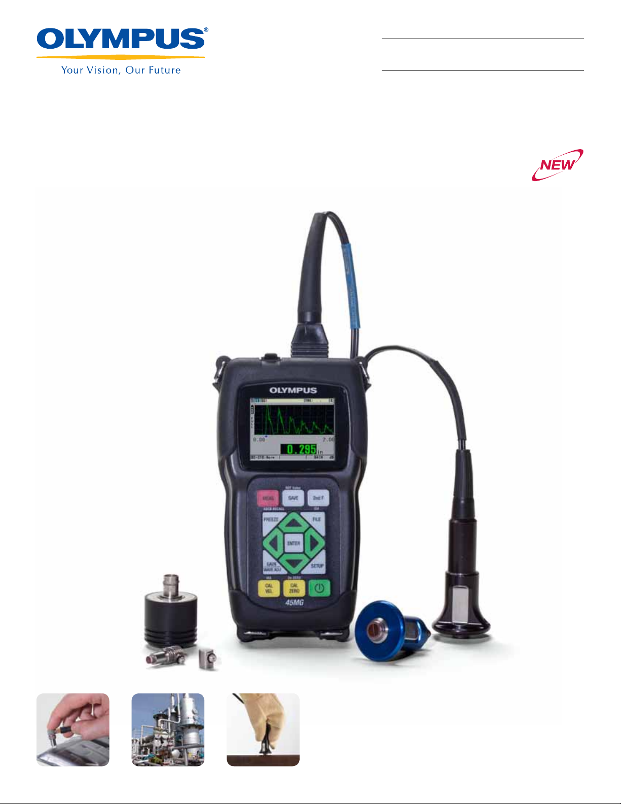
45MG Ultrasonic Thickness Gage
Simple Operation, Rugged, and Reliable
Ultrasonic Thickness Gage
45MG
Shown with optional waveform
• Color Transflective QVGA Display
• Dual Element Corrosion Gaging
• Precision Thickness Measurements
• Rugged, Designed for IP67
Page 2
45MG Ultrasonic Thickness Gage:
Simple Operation, Rugged, and Reliable
The 45MG is an advanced ultrasonic thickness gage packed
with standard measurement features and software options.
This unique instrument is compatible with the complete range
of Olympus dual element and single element thickness gage
transducers, making this innovative instrument an all-in-one
solution for virtually every thickness gage application.
Built for Tough Environments
• Rugged, designed for IP67
• Explosive Atmosphere: Safe operation as defined by Class I,
Division 2, Group D, as found in the National Fire Protection
Association Code (NFPA 70), Article 500, and tested using
MIL-STD-810G, Method 511.5, Procedure I.
• Vibration tested using MIL-STD-810G, Method 514.6,
Procedure I
• Drop tested using MIL-STD-810-G, Method 514.6,
Procedure IV
• Shock tested using MIL-STD-810G, Method 516.6,
Procedure I
• Wide operating temperature range
• Optional protective rubber boot with gage stand
Designed for Easy Operation
• Simple keypad for right hand/left hand operation
• Easy operator interface with direct access to most functions
• Internal and removable MicroSD memory card storage
• USB communication port
• Optional alphanumeric data logger with 475,000 thickness
readings or 20,000 waveforms
• Default/Custom single element transducer setups (optional)
• Password protected instrument lock
• Color transflective QVGA display with indoor and outdoor color
settings for superior clarity
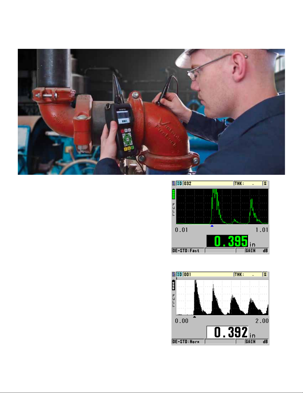
Indoor display setting, optional A-scan mode
Outdoor display setting, optional A-scan mode
2
Page 3
Standard Features
In its basic configuration the 45MG is a simple and straightforward gage that requires minimal operator training to tackle
most common thickness gaging applications. With additional optional software options and transducers however,
the 45MG can become significantly more advanced and
take on applications well beyond that of a typical entry-level
gage. Furthermore, most options are available individually at
the time of purchase or can be added in the future as your
needs change.
• Compatible with full line of Olympus dual element
transducers for thickness measurements on internally
corroded metals
• Min./Max. mode
• Two Alarm modes
• Dierential mode
• Time-based B-scan
• Reduction Rate
• Gain Adjust (standard, high, and low)
• Password instrument lock
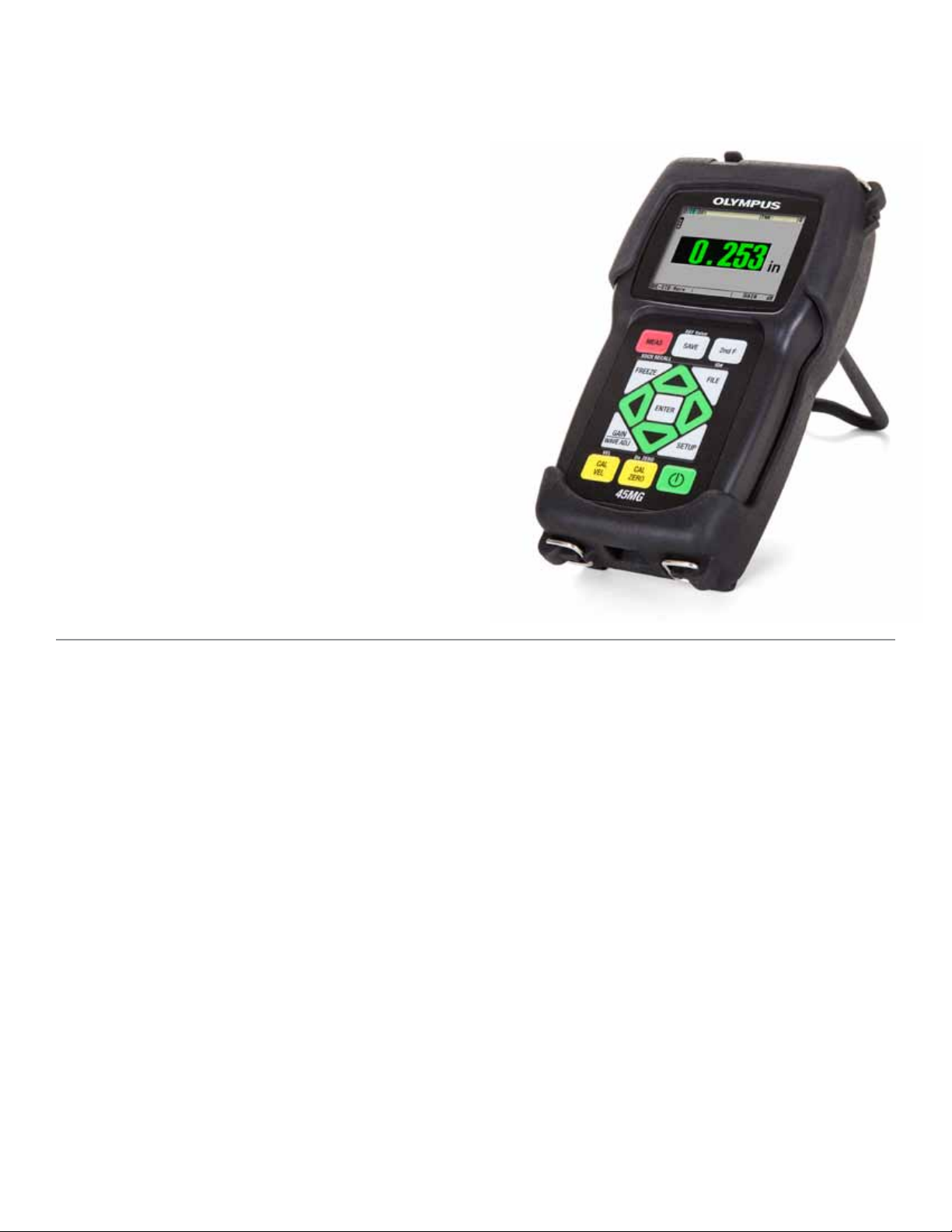
45MG with optional protective rubber boot and stand
Optional Features
From a simple corrosion gage to a multi-purpose precision thickness gage
with only a few key strokes
The 45MG oers five code-activated software options that
makes it one of the most versatile thickness gages in the
industry.
Echo-to-Echo / THRU- COAT
Using Echo-to-Echo, the true metal thickness is displayed
and the thickness of the coating layer will be ignored.
THRU-COAT measures metal and nonmetallic coating thicknesses, each adjusted for their correct sound velocities.
There is no need to remove paint or coatings from surfaces.
Single Element
For very precise thickness measurements on many materials, including metals, plastics, composites, glass, and ceramics. Compatible with single element Microscan transducers ranging from 2.25 MHz to 30 MHz.
Single Element High Penetration
For thickness measurement on thick or highly attenuating
materials such as fiberglass or cast metals. Compatible with
single element Microscan transducers ranging from 0.5 MHz
to 30 MHz. Included is the Single Element option.
®
Data Logger
The 45MG has a full-featured internal bidirectional alphanumeric data logger that is designed to easily store and transfer
thickness readings and waveform data. Includes GageView™
interface program, a Windows-based application.
Live A-scan with Waveform Adjust
This optional Live A-scan mode allows users to view the
ultrasound waveform (or A-scan) directly on the gage’s display, verify the thickness measurement, and make manual
adjustments to gain and blanking settings to maximize
measurement performance in challenging applications. This
helpful option features Manual Gain Adjust, Extended Blanking, First Echo Blank, Range, and Delay.
3
Page 4
Thickness Measurements on
Internally Corroded Metals
Using Dual Element Transducers
One of the major applications of the 45MG is measuring
the remaining thickness of pipes, tubes, tanks, pressure
vessels, ship hulls, and other structures aected by corrosion or erosion. Dual element transducers are most commonly used for these applications.
• Automatic Probe Recognition for standard D79X series
dual element transducers
• Calibration Doubling warning when echo doubling may
occur during calibration
• The Echo-to-Echo / THRU-COAT® option allows for
measurements on painted and coated surfaces
• High temperature measurements; up to 500 °C (932 °F)
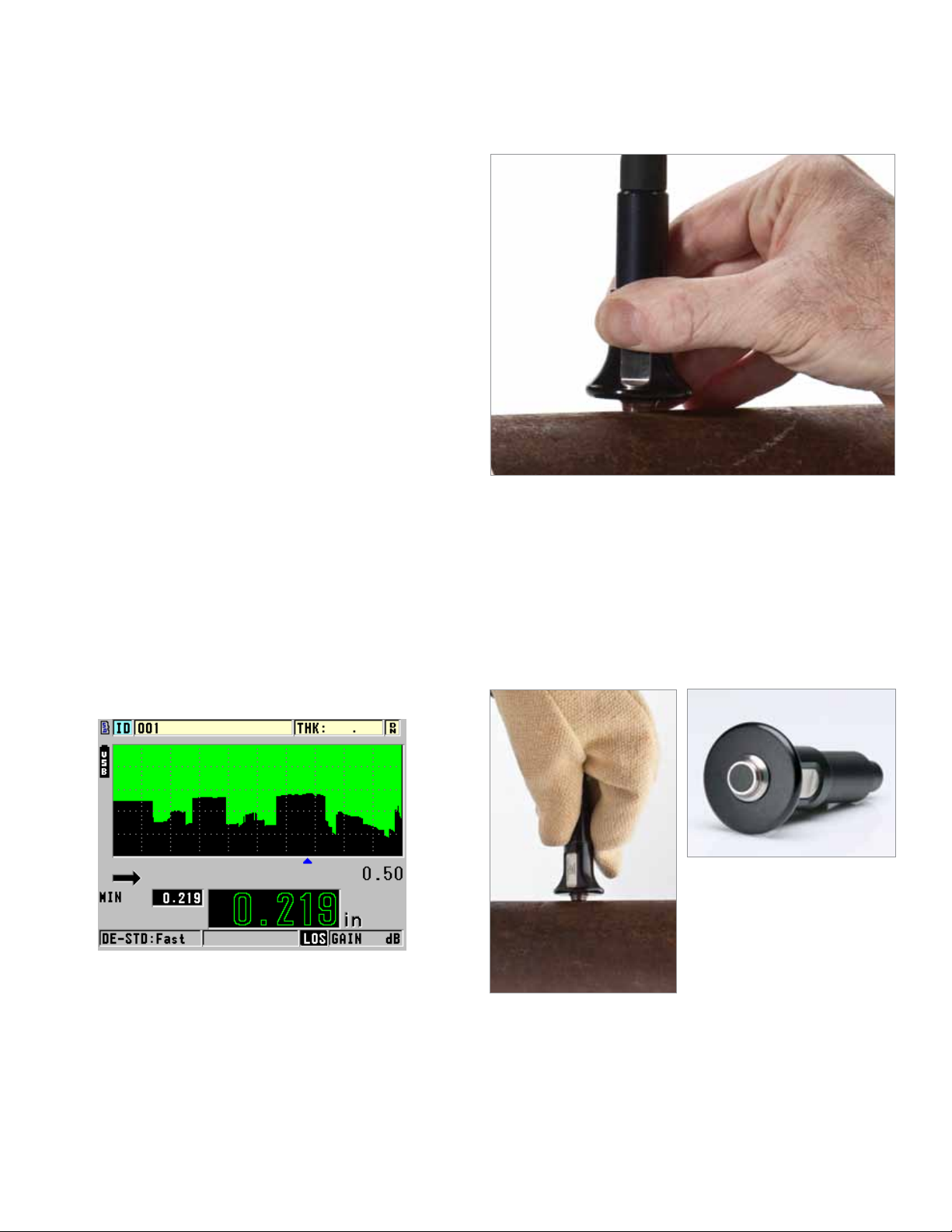
B-scan Mapping (Time-based)
The 45MG gage B-scan feature converts live thickness
readings into cross-sectional images drawn on the display.
This standard feature is very helpful in viewing the changes
in thickness measurements over a distance. The B-scan
is activated as soon as the transducer makes contact with
the surface of the material. The Freeze Minimum function
is used to display the minimum thickness of the scanned
area. The optional 45MG datalogger can store up to
10,000 thickness readings in a single B-scan.
High-Temperature Surfaces
The 45MG is ideally suited for making stable thickness
measurements on hot material surfaces (up to 500 ºC or
932 ºF) with the D790 series transducers (D790, D790 -SM,
D790-RL, and D790-SL). The Zero Compensation feature of
the 45MG enhances the accuracy of measurements on hot
surfaces by compensating for temperature changes in the
transducer delay line due to thermal drift.
D790-SM Transducer on high-temperature
pipe
Indoor display setting, B-scan mode
4
Page 5

Echo-to-Echo / THRU-COAT® Option
Echo-to-Echo
The gage displays the true metal thickness and ignores
the thickness of the coating layer, using multiple back-wall
echoes:
• Auto Echo-to-Echo
• Manual Echo-to-Echo (with A-scan option only) that allows:
- Gain Adjust
- Extended Blanking
- Echo Blanking
THRU- COAT Technology
Uses a single back-wall echo to
measure true metal thickness. You
can display the metal and coating
thicknesses, each adjusted for their
correct material sound velocities.
There is no need to remove paint
and coatings from surfaces.
THRU-COAT measurements use the
D7906-SM, D7906-RM, and D7908
dual element transducers.
Auto Echo-to-Echo mode with A-scan
Manual Echo-to-Echo adjusting the First Echo blank
THRU-COAT mode showing thickness of coating and steel
(waveform not activated)
THRU-COAT mode with optional waveform
5
Page 6

Dual Element Transducers for Corrosion Gaging
All standard dual element transducers feature Automatic Probe Recognition, which automatically recalls a default V-path
correction for each specific transducer.
Transducer
Item
Number
D790 U8450002
D790-SM U8450009 Straight LCMD-316-5B
D790-RL U8450007 90° LCLD-316-5G
Freq.
(MHz)
5.0
Connector
Straight
Tip Dia.
mm (in.)
11.00
(0.434)
Range (Steel)*
mm (in.)
1.00 to 500.00
(0.040 to 20.000)
Temp. Range**
°C (°F)
–20 to 500
(–5 to 932)
Cable
Potted —
†
U8800353
†
U8800330
D790-SL U8450008 Straight LCLD-316-5H U8800331
D791 U8450010 5.0 90°
D791-RM U8450011 5.0 90°
D792 U8450012
D793 U8450013 90° Potted —
10
Straight
D794 U8450014 5.0 Straight
D797 U8450016
D797-SM U8450017 Straight LCMD-316-5D U8800355
D7226 U8454013
D798-LF U8450019
D798 U8450018
D798-SM U8450020 Straight LCMD-316-5J U8800357
2.0
7.5 90°
7.5
90°
90°
D799 U8450021 5.0 90°
MTD705 U8620225 5.0 90°
††
D7906-SM
D7906-RM
††
D7908
* Thickness range dependent on material, transducer type, surface conditions, and
temperature. Full range may require Gain Adjust.
** Maximum temperature with intermittent contact only
U8450005
††
U8450025 90° LCMD-316-5N U8800647
5.0
U8450006 7.5 90°
Straight
11.00
(0.434)
11.00
(0.434)
7.20
(0.283)
7.20
(0.283)
22.90
(0.900)
8.90
(0.350)
7.20
(0.283)
11.00
(0.434)
5.10
(0.200)
11.00
(0.434)
7.20
(0.283)
1.00 to 500.00
(0.040 to 20.000)
1.00 to 500.00
(0.040 to 20.000)
0.50 to 25.00
(0.020 to 1.000)
0.75 to 50.00
(0.030 to 2.000)
3.80 to 635.00
(0.150 to 25.000)
0.71 to 100.00
(0.028 to 4.000)
0.71 to 100.00
(0.028 to 4.000)
1.00 to 500.00
(0.040 to 20.000)
1.00 to 19.00
(0.040 to 0.750)
1.00 to 50.00
(0.040 to 2.000)
1.00 to 37.00
(0.040 to 1.500)
†
Stainless steel cable available; consult Olympus NDT for details.
††
Transducers used with THRU-COAT® technology
–20 to 500
(–5 to 932)
–20 to 400
(–5 to 752)
0 to 50
(32 to 122)
0 to 50
(32 to 122)
–20 to 400
(–5 to 752)
–20 to 150
(–5 to 300)
–20 to 150
(–5 to 300)
–20 to 150
(–5 to 300)
0 to 50
(32 to 122)
0 to 50
(32 to 122)
0 to 50
(32 to 122)
Potted —
LCMD-316-5C U8800354
Potted —
Potted —
Potted —
Potted —
Potted —
Potted —
LCLPD-78-5 U8800332
LCMD-316-5L U8800358
Potted —
Item
Number
D791
D7908
D790-RL
D790
D791-RM
D790-SL
MTD705
D7906-SM
D790-SM
D797-SM
D793
D792/D794
D7226
D798-LF
D799
D798
6
Page 7

Optional Data Logger and PC Interface
The 45MG has a full-featured internal bidirectional alphanumeric data logger that is designed to easily store and
transfer thickness readings and waveform data. The data logger option includes the GageView™ Interface program.
Data Logger Option
• Internal memory of 475,000 thickness readings or 20,000
waveforms with thickness readings
• 32 Character File name
• 20 Character ID# (TML#)
• 6 file formats: Incremental, Sequential, Sequential with custom
point, 2-D Grid, Boiler, and Manual (from PC) GageView
• Internal and removeable MicroSD memory cards
• File copy with the ability to copy files between internal/remov-
able MicroSD memory cards
• Standard USB communication
• Two-way transfer of single element transducer setups
• Onboard statistical report
• Onboard DB Grid View with three programmable colors
• GageView™ interface program communicates with the 45MG
- using the USB port
- or read and write to a MicroSD memory card
• Direct export of internal files to MicroSD memory card in Excel
compatible CSV (comma-separated values) and .txt format.
GageView Interface Program
• Included with the Data Logger option
• This Windows-based application collects, creates, prints, and
• Creates datasets and surveys
• Stored data editing
• View dataset and survey files; including thickness readings,
• Download and upload thickness surveys to and from the
• Export surveys to spreadsheets and other programs
• Collecting snapshot screens
• Printing reports such as Thickness, Setup Table, Statistics,
• Upgrade the 45MG operating software
• Download and upload single element transducer setup files
Onboard DB Grid View with three programmable colors
manages data from the 45MG.
gage setup values, and transducer setup values
gages
and Color Grid
When viewed on your PC a color coded grid easily flags out-oftolerance thickness conditions.
Measurement reports can easily be generated and printed
containing measurements, ID, and other parameters.
B-scan review screen in the GageView interface program
7
Page 8

Thickness Measurements on Plastics, Metals,
Composites, Glass, Rubber, Ceramics
Using Single Element Transducers
Single element transducers enable you to make accurate
thickness measurements on metals, plastics, composites,
glass, ceramics, and other materials. These transducers
are available in a wide range of frequencies, diameters, and
connector styles. In order to use a single element transducer
with the 45MG, you must purchase either the Single Element
software or the High Penetration software option.
• Single Element software option can display
measurements up to 0.001 mm (0.0001 in.) for single
element transducers from 2.25 MHz to 30 MHz
• High Penetration software option for measurements on
attenuating materials such as fiberglass, rubber, and
thick castings
• Thickness, Velocity, or time-of-flight measurements
• Application Auto-Recall with default and custom setups
to simplify thickness measurements
Ultrasonic thickness measurements are accurate, reliable, and repeatable. Instant
readings can be achieved from one side of a material, making it unnecessary to cut
up or destroy the part.
Single Element Software Option
The Single Element software option enables you to make
very precise thickness measure ments at a resolution of up
to 0.0001 in. or 0.001 mm. Compatible with single element
Microscan transducers ranging from 2.25 MHz to 30 MHz.
• Most materials, from thin to thick
• Plastic bottles, tubes, pipes, sheets as thin as
0.08 mm (0.003 in.)
• Metal containers, steel coils, machined parts as thin as
0.10 mm (0.004 in.)
• Cylinder bores, turbine blades
• Glass bulbs, bottles
• Thin fiberglass, rubber, ceramics, and composite
materials
• Curved areas or containers with small radii
Single Element High Penetration
Software Option
This option allows you to use low frequency single element
transducers (as low as 0.5 MHz) to measure thick or highly
attenuating materials such as rubber, fiberglass, castings,
and composites. Included is the Single Element option.
• Most thick or sound-attenuating materials
• Thick cast metal parts
• Thick rubber tires, belts
• Fiberglass boat hulls, storage tanks
• Composite panels
• Resolution of 0.01 mm (0.001 in.) for transducer
frequencies of 0.5 MHz and 1.0 MHz
Measure depth to steel ply / cords in
rubber conveyor belts or tires.
8
Many cast metal parts or highly
attenuating materials can be measured
with the High Penetration software
option.
Page 9

Application Setup Recall
Application Setup Recall simplifies making thickness
measurements. Select any of the stored transducers and
the 45MG gage recalls all relevant internal transducer
parameters.
Stored Standard Setups
The 45MG includes 21 standard single element transducer
setups for the most common applications. These default
transducer setup can be used on wide variety of thickness
applications.
Stored Custom Setups
The 45MG can store up to 35 custom single element transducer setups including calibration information. You can connect the appropriate transducer and recall the setup file and
the instrument is ready to make thickness measurements on
even the most dicult applications.
Material Sound Velocity
Measurements
The 45MG has the capability to make material sound velocity measurements. This standard feature is useful in applications where the speed of sound within the material can be
correlated to other properties. Typical applications include
cast metals to monitor the degree of nodularity, and composites/fiberglass to monitor variations in density.
Reduction Rate Measurements
Dierential Mode and Reduction Rate Mode are standard
features on the 45MG. Dierential Mode shows the thickness variation from a pre-set thickness value. Reduction
Rate calculates and displays the percent of thickness reduction after a material thinning process. A typical application is
automotive sheet steel that is bent and formed to make car
body panels.
Measure thin glass with a V260-SM Sonopen
Measure metal thinning caused by bending or forming.Measure thin plastic material using a 20 MHz delay line transducer.
®
transducer. Measure the thickness of many materials including plastic, metal, rubber, glass,
ceramic, and composites.
9
Page 10

Single Element Transducers for
Precision Thickness Measurements
Contact Transducers
Frequency
(MHz)
0.5 25 1.00 M101-SB* U8400017
1.0 25 1.00 M102-SB* U8400018
1.0 13 0.50 M103-SB* U8400020
2.25 13 0.50 M106-RM
2.25 13 0.50 M1036 U8400019
5.0 13 0.50 M109-RM
5.0 6 0.25 M110-RM
10 6 0.25 M112-RM
10 3 0.125 M1016 U8400015
20 3 0.125 M116-RM
20 3 0.125 M116H-RM** U8400037
* These transducers can only be used with the High Penetration software option.
** Use with spring loaded holder
Element
Diameter
mm inches
Transducer
M106-SM
M109-SM
M110-SM
M110H-RM**
M112-SM
M112H-RM**
M116-SM
Item
Number
U8400023
U8400025
U8400027
U8400028
U8400030
U8400031
U8400029
U8400034
U8400035
U8400033
U8400038
U8400039
m101-sb
m106-rm
m106-sm
m109-rm
m103-sb
m109-sm
m116-sm
m102-sb
m112-sm
m116-rm
m1036
m110-rm
m112-rm
m1061
Sonopen
®
Transducers
The Sonopen transducer has
a replaceable delay line that is
tapered to a small contact area.
This transducer makes reliable thickness measurements
in applications such as turbine
blades and tight radii on plastic
containers.
dlp-301
Sonopen – 15 MHz, 3 mm (0.125 in) transducer
Straight Handle Right Angle Handle 45° Handle
Part
V260-SM U8411019 V260-RM U8411018 V260-45 U8411017
v260-45 v260-sm v260-rm
Item
Number
Part
Immersion Transducers
Panametrics Microscan immersion transducers are designed
to transmit and receive ultrasound in water. Thickness measurements by immersion technique are often preferred when
the test piece has a complex geometry or in on-line applications. Typical o-line applications include wall thickness
measurements on small diameter plastic or metal tubing,
scanned or rotary measurements and thickness measurements on sharply curved parts. Transducer focusing may be
necessary depending on the application.
Sonopen – Replaceable Delay
Lines
Item
Number
Part
Frequency
(MHz)
2.25 13 0.50 M306-SU U8410027
5.0 13 0.50 M309-SU U8420001
5.0 6 0.25 M310-SU U8420004
10 6 0.25 M312-SU U8420008
15 6 0.25 M313-SU U8420009
20 3 0.125 M316-SU U8420011
Item
Number
Element Diameter
mm inches
Tip Diameter
mm inches
2.0 0.080 DLP-3 U8770086
1.5 0.060 DLP-302 U8770088
2.0 0.080 DLP-301
†
High temperature delay for use up to
175° C (350° F)
Transducer
Part
†
Item
Number
U8770087
Item
Number
RBS-1 Immersion Tank
The RBS-1 immersion tank is designed to simplify ultrasonic
thickness measurements using immersion techniques.
10
Page 11

Delay Line Transducers
Microscan delay line transducers provide excellent performance on very thin materials, at elevated temperatures,
or with applications that require a high degree of thickness resolution.
Freq.
(MHz)
0.5 25 1.00 M2008* U8415001 —
2.25 13 0.50 M207-RB U8410017 —
5.0 13 0.50 M206-RB U8410016 —
5.0 6 0.25 M201-RM U8410001 —
5.0 6 0.25 M201H-RM U8411030 2127 U8770408
10 6 0.25
10 6 0.25 M202H-RM U8507023 2127 U8770408
10 3 0.125
20 3 0.125
20 3 0.125 M208H-RM U8410018 2133 U8770412
20 3 0.125 M2055** U8415013 —
30 6 0.25 V213-BC-RM** U8411022 —
* These transducers can only be used with the High Penetration software option.
** Delay line is not replaceable on these transducers.
Replaceable Delay Lines
Element
Diameter
mm inches
Transducer
M202-RM
M202-SM
M203-RM
M203-SM
M208-RM
M208-SM
Item
Number
U8410003
U8410004
U8410006
U8410007
U8410019
U8410020
Holder
—
—
—
Element
Diameter
Delay lines function as a protective buer
between the surface of the test piece and the
transducer element.
mm inches mm inches mm inches mm inches
13 0.50 DLH-2 U8770062 25 1.0 13 0.5 13 0.5
6 0.25 DLH-1 U8770054 25 1.0 13 0.5 13 0.5
3 0.125 DLH-3 U8770069 13 0.5 5 0.2 5 0.2
* Exact range depends on material sound velocity, transducer frequency, part geometry, and surface
condition.
Item
Number
Part
m206-rb
Delay Line
Number
m2055
m208
Item
m2008
m201
Steel - Mode 2 Steel - Mode 3 Plastic - Mode 2
m202
2127
m208h
Maximum Thickness
Measurement Limit*
2133
Additional products available at www.olympus-ims.com
Couplants
Liquid couplant is almost always
necessary to provide acoustic coupling
between the transducer and the test
piece. We oer various types of couplants to suit virtually all applications.
Calibration Test Blocks
Test blocks are necessary for the calibration of ultrasonic thickness gages
and should be used to maintain and
verify the accuracy, dependability, and
reliability of ultrasonic measurements.
Blocks are held to tighter tolerances
than stated in ASTM E797 code.
Metric test blocks are available.
Transducer Cables
A wide selection of transducer cables
suitable for all ultrasonic thickness
gaging instrumentation.
• Standard
• Waterproof
• Heavy Duty
- Teflon
- Armored PVS Jacket
- Armored Silicone Jacket
- Stainless Steel
11
Page 12

45MG Specifications*
MEASUREMENTS
Dual element transducer
measurement mode
Echo-to-Echo
(optional)
THRU-COAT
measurement (optional)
Single element
transducer
measurement modes
(optional)
Thickness range 0.080 mm to 635 mm (0.003 in. to 25.0 in.) depending on material,
Material velocity range 0.508 mm/s to 18.699 mm/s (0.020 in./s to 0.7362 in./s)
Resolution (selectable) Low: 0.1 mm (0.01 in.)
Transducer frequency
range
®
Time interval from a precision delay after the excitation pulse to the first echo
Time interval between two successive back-wall echoes to eliminate paint or
coating thickness
Measurement of true metal and coating thicknesses with a single back-wall
echo (with D7906-SM, D7906-RM, and D7908 transducers)
Mode 1: Time interval between the excitation pulse and the first back-wall echo
Mode 2: Time interval between the delay line echo and the first back-wall
echo (with delay or immersion transducers)
Mode 3: Time interval between successive back-wall echoes following the
first interface echo after the excitation pulse (with delay line or
immersion transducers)
transducer, surface conditions temperature, and selected configuration
(Full range requires single element option)
Standard: 0.01 mm (0.001 in.)
Single Element option: 0.001 mm (0.0001 in.)
Standard: 2.25 MHz to 30 MHz (–3 dB)
High Penetration (Single Element option): 0.50 MHz to 30 MHz (–3 dB)
GENERAL
Operating temperature
range
Keypad Sealed, color-coded keypad with tactile and audible feedback
Case Impact-resistant and water-resistant, gasketed case with sealed connectors.
Dimensions (W x H x D) Overall: 91.1 mm x 162 mm x 41.1 mm (3.59 in. x 6.38 in. x 1.62 in.)
Weight 430.9 g (0.95 lb)
Power supply 3 AA batteries/USB power supply
Battery life operating
time
Standards Designed for EN15317
Explosive Atmosphere Safe operation as defined by Class I, Division 2, Group D, as found in the
–10 °C to 50 °C (14 °F to 122 °F)
Designed for IP67.
3 AA alkaline: 20 to 21 hours
3 AA NiMH: 22 to 23 hours
3 AA Lithium-ion: 35 to 36 hours
National Fire Protection Association Code (NFPA 70), Article 500, and tested
using MIL-STD-810G, Method 511.5, Procedure !
DISPLAY
Color transflective
QVGA display
Rectification Full wave, RF, half-wave positive, or half-wave negative (Waveform option)
Liquid crystal display, display area 54.61 mm x 41.15 mm (2.15 in. x 1.62 in.)
INPUTS/OUTPUTS
USB 2.0 client
Memory card Maximum capacity: 2 GB removable MicroSD memory card
INTERNAL DATA LOGGER (Optional)
Data logger The 45MG identifies, stores, recalls, clears, and transmits thickness readings,
Capacity 475,000 thickness measurements or 20,000 waveforms with thickness
File names, IDs, and
comments
File structures Six standard or custom application-specific file structures
Reports On-gage reporting of summary with statistics, Min./Max. with locations, Min.
waveform images, and gage configuration information through USB or MicroSD.
measurements
32-character file names and 20-character alphanumeric location codes with
four comments per location
review, file comparison, and alarm report
Standard Package
• 45MG digital ultrasonic thickness gage
• AA alkaline batteries
• 2-step test block and couplant
• USB cable
• User’s manual on CD
• Measurement features: Min./Max.
mode, two alarm modes, Dierential
mode, B-scan, Reduction Rate,
Programmable Lock
Software Options
• 45MG-SE (U8147022): Single
Element option to use single element
transducers with frequency range of
2.25 MHz to 30 MHz.
• 45MG-HP (U8147023): Single Element
High Penetration option to use single
element transducers with frequency
range of 0.5 MHz to 30 MHZ.
• 45MG-EETC (U8147021):
Echo-to-Echo and THRU-COAT
®
• 45MG-WF (U8147019): Waveform
option
• 45MG-DL (U8147020): Internal
data logger including GageView
interface program
Optional Accessories
• MICROSD-ADP-2GB (U8779307):
2 GB External MicroSD memory card
• 45MG-RPC (U8779676): Rubber
protective boot with stand
www.olympus-ims.com
For enquiries - contact
www.olympus-ims.com/contact-us
48 Woerd Avenue, Waltham, MA 02453, USA, Tel.: (1) 781-419-3900
12569 Gulf Freeway, Houston, TX 77034, USA, Tel.: (1) 281-922-9300
505, boul. du Parc-Technologique, Québec (Québec) G1P 4S9, Tel.: (1) 418-872-1155
1109 78 Ave, Edmonton (Alberta) T6P 1L8
*All specifications are subject to change without notice.
All brands are trademarks or registered trademarks of their respective owners and third party entities.
Copyright © 2012 by Olympus NDT.
is ISO 9001 and 14001 certified
45MG_EN_201211•Printed in the USA•P/N: 920-255-EN Rev. C
 Loading...