

Page 1
Modular Electronic Load
MODEL 4200
T 60 A, 120 V, 300 W module
T Waveform capture and display
T 26 Voltage, Current, Power and Timing Measurements
T Transient Generator
T Glitchless Mode Changes
TEST PRINTOUT
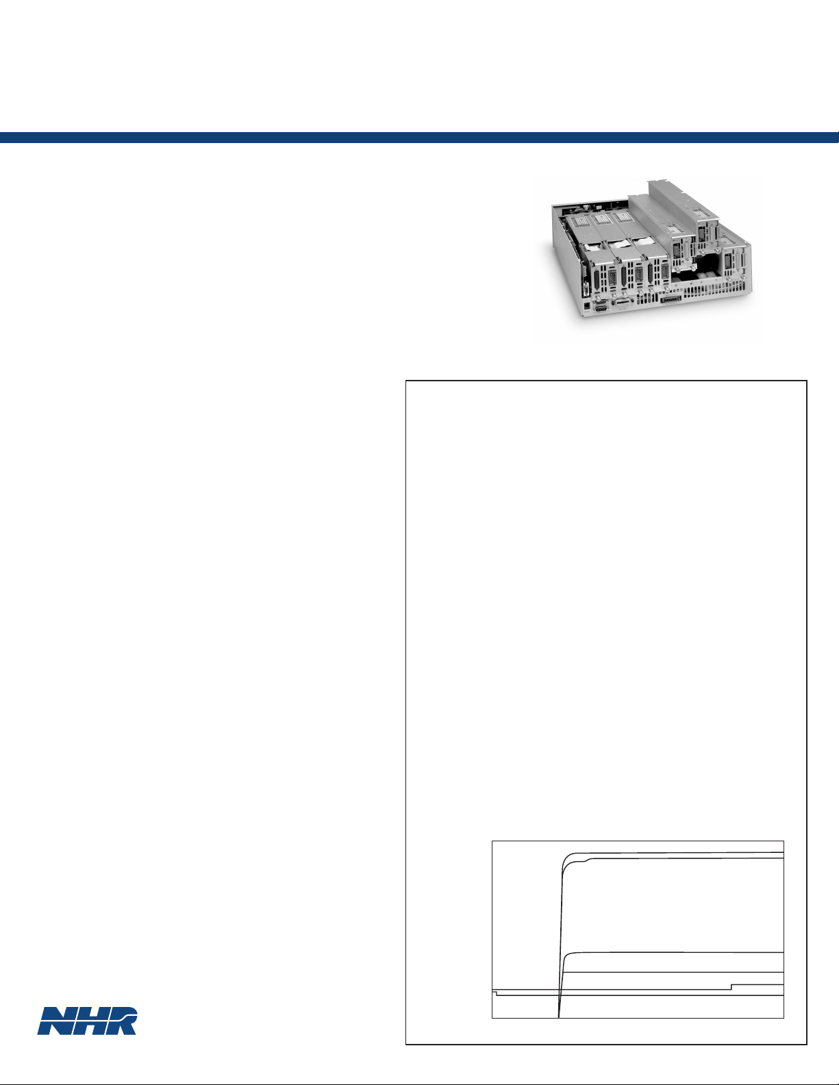
The 4200 load is designed for use within the mainframe power module chassis included as part of the
NHR S400 and 5600 power supply test systems. This
load provides advanced control and measurement
capabilities by incorporating the task-essential features of a DMM, DSO and ARB. With this built-in
capability, the 4200 load delivers a single integratedtest-solution that provides more comprehensive test
information. The load also eliminates the additional
cost, reliability and test-speed penalties when multiple
single-purpose instruments are necessary to supplement a less capable load.
WAVEFORM CAPTURE, ANALYSIS AND DISPLAY
The 4200 load digitizes device-under-test output voltage and current waveforms for both analysis and display. The advantage of each load having this capability is that any number and type of output waveform-towaveform measurements such as timing can now be
made within a single test step. Further, all the waveforms and digital control signals can be combined
together on a single screen. With this additional layer
of visual information the designer or test engineer has
a higher level of product performance information
than would be available from just a strict numeric
record of test results.
Step Label Minimum Actual Maximum Result
1 Turn-On @ Full Load
+5V
Turn-on Time (V) 0.000 S 124.720 mS 1.000 S Pass
Rise Time (V) 0.000 S 8.690 mS 20.000 mS Pass
Settle Voltage 4.750 V 4.797 V 5.250 V Pass
Peak Voltage 4.750 V 4.950 V 5.250 V Pass
Overshoot (V) 0.000 V 152.608 mV 250.000 mV Pass
+12V
Turn-on Time (V) 0.000 S 124.810 mS 1.000 S Pass
Rise Time (V) 0.000 S 9.480 mS 20.000 mS Pass
Settle Voltage 11.400 V 12.173 V 12.600 V Pass
Peak Voltage 11.400 V 12.219 V 12.600 V Pass
Overshoot (V) 0.000 V 45.974 mV 600.000 mV Pass
-12V
Turn-on Time (V) 0.000 S 123.580 mS 1.000 S Pass
Rise Time (V) 0.000 S 18.290 mS 20.000 mS Pass
Settle Voltage 11.400 V 11.683 V 12.600 V Pass
Peak Voltage 11.400 V 11.754 V 12.600 V Pass
Overshoot (V) 0.000 V 70.527 mV 600.000 mV Pass
+3.3V
Turn-on Time (V) 0.000 S 118.870 mS 1.000 S Pass
Rise Time (V) 0.000 S 3.500 mS 20.000 mS Pass
Settle Voltage 3.135 V 3.318 V 3.465 V Pass
Peak Voltage 3.135 V 3.363 V 3.465 V Pass
Overshoot (V) 0.000 V 44.956 mV 165.000 mV Pass
+5VSB
Settle Voltage 4.750 V 4.782 V 5.250 V Pass
Peak Voltage 4.750 V 4.909 V 5.250 V Pass
Additional Measurements
PS_ON to +5V @ 95% Time 20.000 mS 118.002 mS 200.000 mS Pass
PS_ON to PWR_
GOOD High Time 20.000 mS 402.490 mS 500.000 mS Pass
PWR_GOOD Delay Time 20.000 mS 284.488 mS 350.000 mS Pass
13 13 13 13
11 11 11 11
10 10 10 10
8888
7777
5555
3333
2222
0000
+5V Volts
+3.3V Volts
-12V Volts
+12V Volts
............................................................................................
.......................................................................................................................................................
.......................................................................................................................................................
.......................................................................................................................................................
.......................................................................................................................................................
.......................................................................................................................................................
.......................................................................................................................................................
.......................................................................................................................................................
+5V: 100.000 KS/sec
-12V: 100.000 KS/sec
+3.3V: 100.000 KS/sec
+12V: 100.000 KS/sec
............................................................................................
............................................................................................
............................................................................................
............................................................................................
............................................................................................
............................................................................................
50.000 mS/Div
............................................................................................
............................................................................................
PWR_GOOD
PS_ON
Page 2
AUTO MODE
.
.
.
.
.
.
.
.
.
.
.
.
.
.
.
.
The 4200 contains a unique Auto Mode that provides glitchless automatic switching between CR,
CC, CV and CP limits. Previously challenging tests
that are now made possible include turn-on into a
CR load, confirming the complete V-I curve for
lithium-Ion battery chargers, and preventing deviceunder-test blowup should a protection circuit fail.
POWER SUPPLY TURN-ON VOLTAGE & CURRENT
WAVEFORMS IN AUTO MODE
50 KS/SEC 50 KS/SEC
.........................................................................................................................
.........................................................................................................................
.........................................................................................................................
.........................................................................................................................
.........................................................................................................................
.........................................................................................................................
.........................................................................................................................
.........................................................................................................................
.........................................................................................................................
.......................................................................................................................................................
.......................................................................................................................................................
.......................................................................................................................................................
POWERFUL TRANSIENT GENERATOR
A greatly expanded range of single burst or continuous waveforms are now possible through the built-in
waveform/transient generator. Almost any waveform
can be created with up to100 programmable steps.
Waveforms can be programmed in the CV, CP and
CR modes as well as the customary CC mode.
COMPATIBLE WITH THE HIGHLY FLEXIBLE POWER
MODULE SUBSYSTEM
Within the mainframe power module chassis, the
Model 4200 may be combined with Model
4100/4110 loads as well as 6000/6100 Series DC
sources. The 4200 is also software parallelable,
which allows real time reconfiguration of larger, virtual loads. In this manner, the load creates another
dimension of power module flexibility that assures
adapting to new numbers of outputs and power level
needs in the future.
.......................................................................................................................................................
.......................................................................................................................................................
.......................................................................................................................................................
.......................................................................................................................................................
10.000 mS/div
Wf1, Chn 001, 5 V/div.
Wf2, Chn 004, 500 mA/div.
Wf1 = Vout; Wf2 = lout
Trigger: WF 1, Rising @ 800.000 mV, DC Coupled
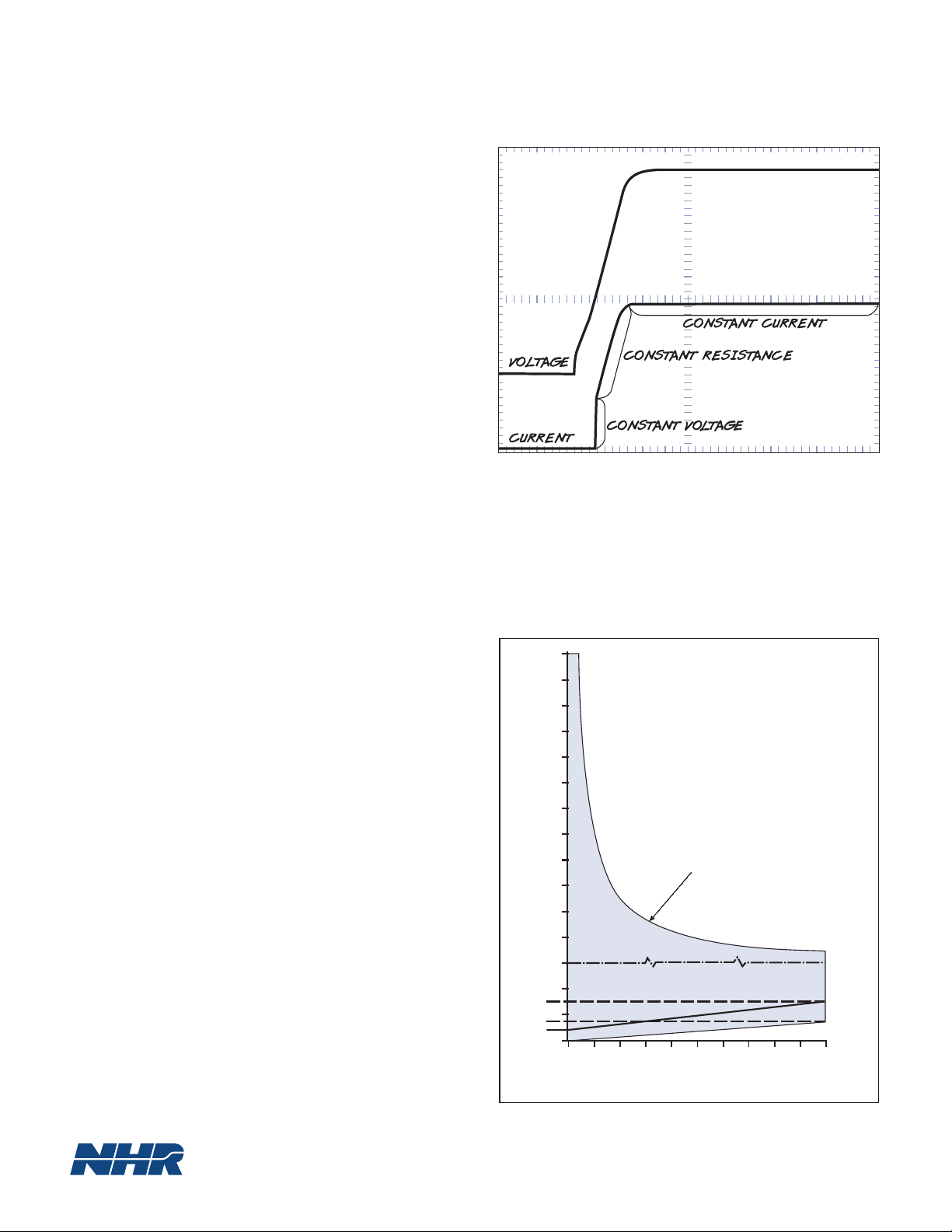
OPERATING CONTOUR
120
110
100
90
80
70
60
50
40
VOLTS
30
20
10
3
2
1.5
1
0.7
0.4
0
0 6 12 18 24 30 36 42 48 54 60
300W Constant Power
SCALE CHANGE
CR MODE ONLY
AMPS
Page 3

MODEL 4200 SPECIFICATIONS
1
PROGRAMABILITY
Constant Current
Ranges 0 to 0.6, 6.0, 60 A
Accuracy 0.06% + 0.06%
Resolution 0.025%
Constant Voltage
Ranges 0.15 to 6.0, 60, 120 V
Accuracy 0.05% + 0.05%
Resolution 0.025%
Constant Resistance
Ranges 0.02 to 5 k⍀
Accuracy 2%
Constant Power
Ranges 0 to 40, 400 W
Accuracy 1% + 1%
Resolution 0.025%
Transient Generator
Pulse
Current Settings 1 to 100
Total Period 50 µSec to 1 Sec
Delay between Settings 20 µSec to 20 Sec
Resolution 10 µSec
Accuracy 1% ± 5 µSec
Modes Single burst, continuous
Slew Rates_
Ranges 0.6, 6.0, 60A
Maximum 0.03, 0.6, 12A/µSec
External Modulation
Bandwidth DC to 25 kHz
Voltage 0 to 10 V
Accuracy 5% FS
Short Circuit
Resistance 0.012 ⍀ @ 60 A
2
MEASUREMENTS
DC Current
Ranges 0 to 0.6, 6.0, 60 A
Accuracy 0.05% + 0.05%
Resolution 0.002%
DC Voltage
Ranges 0 to 6.0, 60, 120 V
Accuracy 0.01% + 0.02%
Resolution 0.002%
Power
Ranges 0 to 3.6, 36, 72, 360 W
Accuracy 0.06% + 0.07%
Resolution 0.005%
DIN and Trigger Timing
Range To 58 years
Accuracy 0.05% ± 100µSec
Resolution 100 nSec
Waveform Capture
Bandwidth DC to _
Accuracy 1%
Digitizing Rate 100 to100K Samples/Sec__
Memory 256K Samples__
Resolution 0.0015%
Triggering From Mainframe
Measurements Voltage, Current, Overshoot,
1/4
of sample rate
3
Rise Time, Fall-Time,
Settling Time, Hold-Up
Time, AC RMS, AC+DC
RMS, Trigger-In-Time,
DIN Time, DIN State &
Time
3
ADDITIONAL FEATURES
Isolation ±500VDC between input and chassis ground
Remote Voltage Sense 2VDC max drop between sense and load input
OVPS Relay DPDT, 5 A, isolated control
Self Test Power-up self-test of all major functions including each output transistor
Performance Monitoring Continuous checking of performance parameters and appropriate error messages
when necessary
Calibration Closed cover, all adjustments made in software and stored in EEPROM
Protection OP, OC, OV, OT and Reverse Voltage
Trigger Output To initiate an external measurement device and synchronized to programmed load
current step
Current Monitor 0 - 10 V external signal appropriate to 100% current for the selected range
Control RS 232 , RS485
Size (HWD) 4 3/4 x 2 1/2 x 18 in. / 120.7 x 63.5 x 457.2 mm
Weight Module - 6.6 lbs / 3.0 kg., Chassis - 21 lbs / 9.5 kg
Operating Temperature 0 - 50º C, all specifications apply at 23 ± 5º C
Input Power 115/230 VAC, 1Ø
1
All accuracies ± (% of Set/Reading + % of Range). All resolutions % of Range
__
__2 Voltage and Current Slew Rates are in the CC mode and can be programmed separately
__3Single channel capture. Simultaneous Voltage and Current captures would halve sample rate and memory available.
16601 Hale Avenue, Irvine, California 92606
NH Research, Incorporated
Tel: 949-474-3900 • Fax: 949-474-7062
E-mail: sales@nhresearch.com
Page 4

NH Research, Incorporated
16601 Hale Avenue, Irvine, California 92606
Tel: 949-474-3900 • Fax: 949-474-7062
E-mail: sales@nhresearch.com
©Copyright 2007, NH Research Incorporated. All rights reserved.
Printed in USA 2500 PS
Specifications subject to change without notice.
 Loading...