

Page 1
DC Electronic Loads
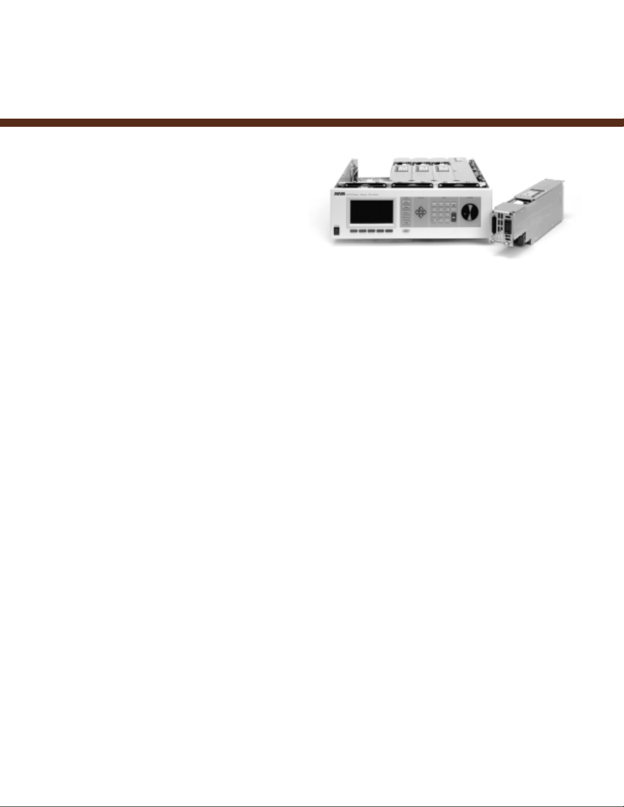
Ultra-Compact, Modular Loads
Model 4100/4110
❑ 300 W, 60 A modules
❑ Up to 6 loads in a 5
1
/4
-inch
high chassis
❑ Parallelable “virtual” loads
❑ Below 1volt operation
The Model 4100 and 4110 electronic loads are
designed for use within the S300 Power Subsystem.
These highly versatile loads may be used in any combination together with DC sources within the same
6-slot chassis. The use of such wide-capability modular loads yields more flexibility, less rack space, and
lower cost than an assortment of loads each having
limited voltage and current range.
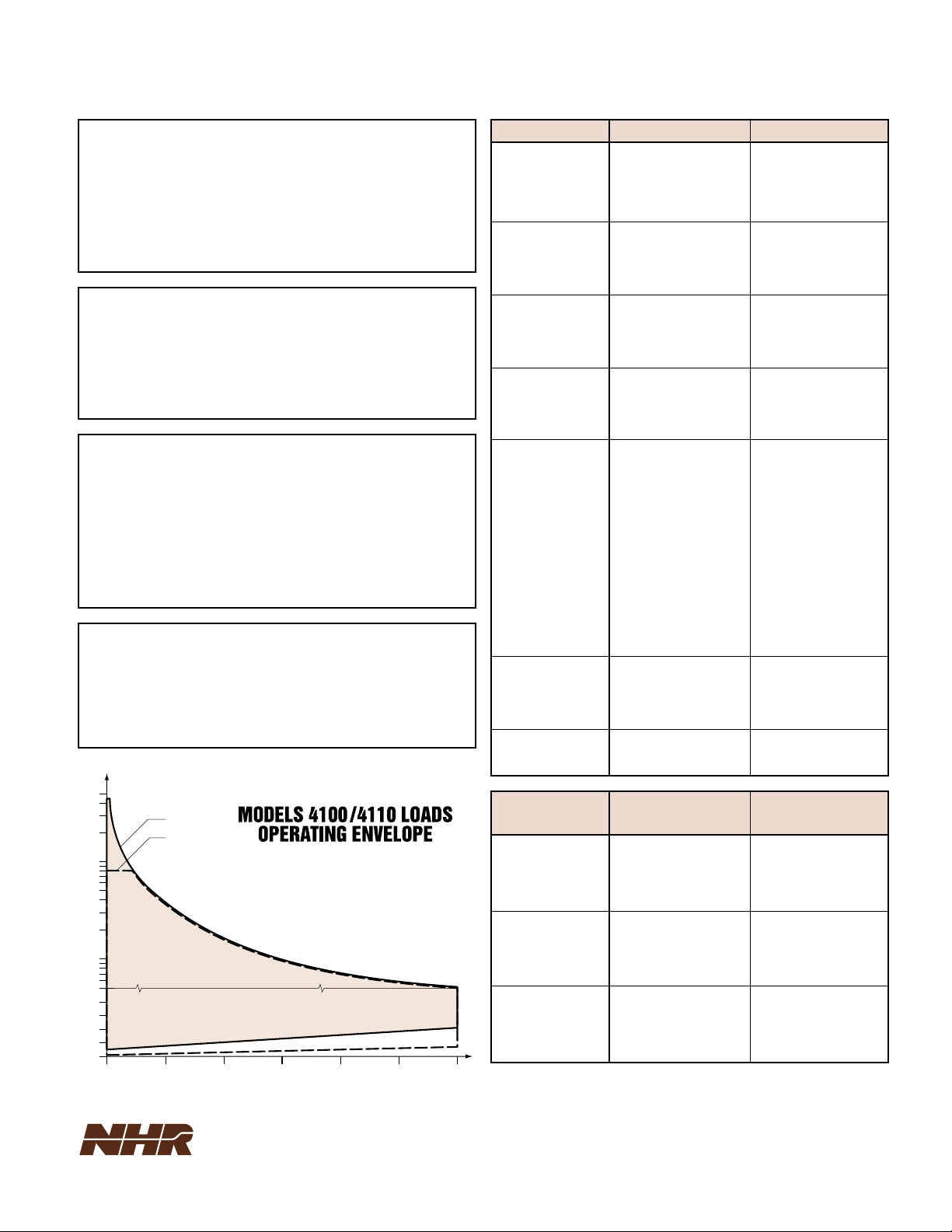
BROAD OPERATING ENVELOPE
To cover the full spectrum of supply-under-test output
voltages, the Model 4100 load operates at full current
from 2.1 to 450 V. To meet newer low voltage requirements, the Model 4110 load operates down to 0.7 V
and at reduced current down to 0.1 V. In the constantcurrent mode, both loads have three ranges in order to
assure the necessary low-end resolution for both set
and measurement values.
PARALLELED “VIRTUAL” LOADS
To address higher power requirements, the same
type (4100 or 4100s) can be paralleled in software
to respond as if they were a single larger load. All
load functions, including slew rate and short-circuit,
are then internally synchronized so that the supplyunder-test sees a single “virtual” load without the
dynamic discontinuities associated with paralleling
older designs. Should the next application require a
different load grouping, reconfiguration is quickly
achieved through reprogramming, thus extending
the system’s flexibility with a minimum of load
modules.
OPERATION BELOW 1 VOLT
With the clear trend toward lower IC voltages,
today’s loads must anticipate tomorrow’s test
requirements. Both the 4100 and the 4110 will operate below 1 V at reduced current levels, with the
latter being optimized for operation at these very
low voltages.
12
Page 2
13
NH Research, Incorporated
16601 Hale Avenue, Irvine, California 92606
Tel: 949-474-3900 • Fax: 949-474-7062
E-mail: sales@nhresearch.com
MODEL 4100/4110 SPECIFICATIONS
PROTECTION CIRCUITS
Over-power: Maximum power is limited through monitoring of heatsink
temperature. Programmable to lower limits.
Over-current:All modes limited to current set in constant current mode
Over-voltage: Output protected for transients over 450 V
Reverse-voltage: Reverse polarity diodes on outputs to short UUT
Over-temperature: Monitor of heatsink temperature
SUPPLEMENTAL CHARACTERISTICS
Size (HWD): Single-slot (six available) of S300 mainframe chassis
(51/4 x 19 x 22-inch)
Weight: Module: 6.6 lbs, Chassis: 21 lb
Operating T emperature: 0 to 50° C
All specifications apply for 27° C ± 5° C
Power (loads only): 115 VAC ± 10%, 208 to 264 VAC, 47 to 63 Hz
ADDITIONAL FEATURES
Mode Switching: Glitch-free transition when changing between current,
voltage, power, and resistance modes
Isolation: ± 500 VDC between input and chassis ground
Remote Sense: 2 VDC max drop between sense and load input
OVPS Relay: DPST, 5A, isolated control
Self-test: Complete built-in hardware self-test of all major functions
including each output transistor
Calibration: Closed cover, all adjustments done in software and stored in
an on-board EEPROM
MODAL OPERATION
4100 4110
Constant Current
Ranges:
0 to 60 A, 6 A, and 660 mA 0 to 60A, 6A, and 660 mA
Accuracy:
60 mA,30 mA, 660 µA + 2 µA/V 60 mA,30 mA, 660 µA + 2 µA/V
Resolution:
0.025% FS 0.025% FS
Constant V oltage
Ranges:
0.5 to 120 V, to 450 V 0.2 to 8V, 0.75 to 80 V
Accuracy:
0.1% FS 0.1% FS
Resolution:
0.025% FS 0.025% FS
Constant Resistance
Ranges:
0.035 to 10 kΩ 0.12 to 10 kΩ
Accuracy:
0.5% Set 0.5% Set
Resolution:
0.15% Set 0.15% Set
Constant Power
Ranges:
0 to 400 W, 40 W 0 to 400 W, 40 W
Accuracy:
1% Set 1% Set
Resolution:
0.1% FS 0.1% FS
Transient Generator
Pulse
Current Settings:
33
Total Period:
40 µsec to 1 sec (25 kHz to 1 Hz) 40 µsec to 1 sec (25 kHz to 1 Hz)
Delay Between
Settings:
20 µsec to 1 sec 20 µsec to 1 sec
Resolution:
10 µsec 10 µsec
Accuracy:
1% + 5 µsec 1% + 5 µsec
Modes:
Single burst, continuous Single burst, continuous
Rise/Fall Time
Range:
10 µsec to 1 sec (10% to 90%) 10 µsec to 1 sec (10% to 90%)
Resolution:
2 µsec 2 µsec
Accuracy:
1% of setting + 3 µsec 1% of setting + 3 µsec
External Modulation
Bandwidth:
DC to 25 kHz DC to 25 kHz
Programming Voltage: 0 to 5V 0 to 5V
Accuracy:
5% FS 5% FS
Short-circuit
Resistance:
0.035 Ω @ 60 A 0.012 Ω @ 60 A
READBACK
INSTRUMENTA TION
4100 4110
DC Current
Ranges:
0 to 60 A, 6 A, 660 mA 0 to 60 A, 6 A, 660 mA
Accuracy:
15 mA, 5m A, 0.3 mA, + 2 µA/V 15 mA, 5 mA, 0.3 mA, + 2µA/V
Resolution:
250, 25, 2.5 µA 250, 25, 2.5 µA
DC V oltage
Ranges:
0 to 120, 450 V 0 to 8, 80 V
Accuracy:
0.025% FS 0.025% FS
Resolution:
500, 1.8 µV 33, 330 µV
Power
Ranges:
0 to 500, 50 W 0 to 500, 50 W
Accuracy:
1% 1%
Resolution:
± 30 mW ± 30 mW
PROGRAMMABLE FEATURES
Current: 0 to 60A
Voltage: 4100 4110
2.1* to 450 VDC 0.7* to 80 VDC
* Full current operation. See graph below for current derating at lower voltages.
Power: 300 W
Modes: Constant current, constant voltage, constant resistance, constant power,
transient generator, short-circuit and external analog modulation
Control: GPIB (IEEE 488.2) or RS485
500
MODEL 4100
MODEL 4110
100
50
LOG VOLTSVOLTS
10
5
0
0 102030405060
SCALE CHANGE
CURRENT
 Loading...