

Page 1
Product Data
Power Amplifier — Type 2706
USES:
❍
To drive the Vibration Exciter Type 4809
❍
To drive the Mini-Shaker Type 4810 safely to full
rating
❍
General purpose power amplifier, supplying for
example 75 W into a 3Ω loudspeaker for
reverberation measurem ents
The Power Amplifier Type 2706 has
been designed to drive small vibration
exciters, particularly the Brüel&Kjær
Vibration Exciter Type 4809. It can
also be use d to driv e the Min i- Shak er
Type 4810 to full rating. For this application, the maximum output current sh ould be l imited to 1.8 A .
The po wer amplifie r has a flat frequency re s po nse from 10Hz to 2 0 kH z
(±0.5 dB). The power output capability is 7 5 VA into a 3Ω exciter o r res istive load and the maximum voltage
gain is 40 dB. This enables the power
amplifier to be used in acoustical
measurement set-ups, even when
third-octav e narrow band noise i s em ployed.
The us e of a tran sform erless p ower
output stage and high negative feedback results in very low harm onic distortion. A balanced preamplifier and
rugged solid-state design results in a
stable instrument which can tolerate
temperature fluctuations and supply
line variations.
FEATURES:
❍
75 VA power output capability
❍
Switcha ble 5 A or 1. 8 A max. curren t limiting
❍
40 dB voltage gain
❍
Built-in attenuator and cont inuously variable gain
control
❍
Low distortion over wide frequen cy range
❍
Built-in protection against shor t-circuit and excess
heat sink temperature
❍
Front panel indicator light showing clipped output
signal
Clipping
5 A
1.8 A
Peak
Current
Limiters
Description
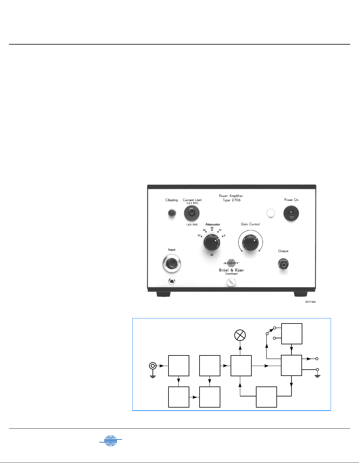
The block diagram for the various circuit functions is shown in Fig. 1.
The input circuitry includes an attenuator for attenuation of the input
signal in 10 dB steps from 0 to 40 dB.
This is followed by a continuously
Brüel & Kjær
B
Input
Fig.1 Block diagram of Power Amplifie r Type 2706
K
Input
Attenuator
Gain
Control
10 µF
Coupling
Capacitor
Preamplifier
Driver
Power
Amplifier
Tempera-
ture
Sensor
272084/2e
Page 2
variable gain control and a preamplifier. The preamplifier is capacitively
coupled to the driver stage, which is
equipped with a clipping detector. Excessive signal levels at the input will
saturate the amplifier and cause clipping of the output waveform. This
will trigger the clipping detector,
which then lights the yellow clipping
warning light on the front panel. The
instrument remains in operation during clipping.
The power stage employs an output
current limiter, which limits the instantaneous positive and negative
peaks of the output current . The power output stage is protected by a temperature sensing device. Abnormal
load conditions, high ambient temperatures or an output short-circuit
could resul t in outpu t transi sto r temperatures well in excess of design
limits. To prevent any subsequent
damage, the temperature protective
circuitry blocks the amplifier input
signal. When the heat-sink temperature reverts to the normal level the
power amplifier will automaticially
regain operation.
Accelerometer
4384
Charge Amplifier
Force Transducer
8200
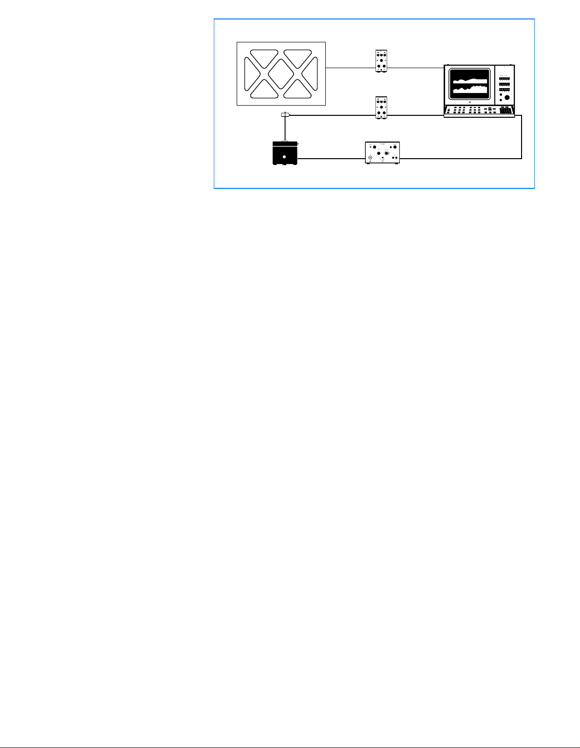
Fig.2 Typical frequency response test set-up
Charge Amplifier
Power Amplifier
Example Of Set-Up
A typi cal fr e qu e nc y re sp o n se test setup for vibration testing is shown in
Fig. 2.
An input forcing signal is taken
directly from the Signal Analyzer
Type 2032 and is fed to the power
2635
2635
2706
Dual Channel Signal
2032
850792/1e
amplifier which drives the Vibration
Exciter Type 4809. The signal analyzer measures the input forcing signal and the structural response
signal and uses them to produce a
representation of frequency response
function of the structure under test.
2
Page 3

Specifications 2706
POWER OUTPUT CAPABILITY:
75 VA into 3Ω exciter or resistive load
CURRENT LIMITING:
Switchable,
Max. 5 A for Vibration Exiter Type 4809
Max. 1.8 A for Mini-S haker Type 4810
FREQUENCY RESPONSE:
10 Hz to 20kHz (±0.5 d B)
2 Hz to 50 kHz (±3dB)
HARMONIC DISTORTION:
< 0.2% (20 Hz to 10 kHz)
< 0.5% (20 Hz to 20 kHz)
at full outp ut capacity
INPUT IMPEDANCE:
Ω
15 k
OUTPUT IMPEDANCE:
<0.04Ω (10Hz to 5kHz)
<0.08Ω (5 kH z to 20 kHz )
PROTECTION:
Short circui t
Excessive heat sink temperatu re
Input overload
DC STABILITY:
< 25 mV drift for ±5% supply line variation
< 25 mV drift for ambient temperature vari ations
between 10 and 40°C (50 and 104°F)
HUM AND NOISE:
<5mV RMS
MAX. VOLTAGE GA IN AT 1 KH Z:
40 dB (±1dB)
ATT EN UATOR :
0 to 40 dB in 10 dB s teps
GAIN CONTROL:
0 to –× dB logari thmic
POWER REQUIREMENTS:
110, 115, 127, 220 and 240 V AC (±5%, 50 to
60 Hz)
Approximately 1 40 VA
Complies with safety class 1 of IEC 348
COMPLIANCE WITH STANDARDS:
CE-mark i ndicates comp liance w ith: EMC Directive a nd Low Voltage Directive.
Safety
EMC Emiss ion
EMC Immunity
Temperature
Humidity
IEC 348: Safety Requirements for Electronic Appara tus
EN 50081– 1: Gener ic emissi on standard. Part 1: Residenti al, comme rcial and
light industr y.
EN 50081 – 2: G eneric emiss ion standard. Par t 2: Ind ustrial environm ent.
CISPR22 : Limits and methods o f radio disturb ance character istics of
information technology equipment. Class B L imits.
FCC Rules, Part 15: Complies with the li mits for a Class B digital device.
EN 50082–1: Generi c immu nity s tand ard . Par t 1: Res iden tial, c omm erci al and
light industr y.
EN 50082 – 2 : Generic immunity standard . Part 2: Ind ustrial envir onment.
Note 1:
The above is guaranteed us ing a cces sori es li sted in t his Pr odu ct Dat a
sheet only.
Note 2:
RF disturbances above 3MHz may result in demodulation and overload
conditions.
IEC68 – 2 – 1 & IE C 68 – 2 – 2: Environmental Testing. Col d and Dry Heat.
Operating Temperature: +5 to +40°C (41 to 104°F)
Storage Temperature: –25 to + 70°C (–13 to 158°F)
IEC68 – 2 – 3: Da mp Heat 90% RH (non-conden sing at 4 0°C (104°F))
DIMENSIONS:
Height:
133 m m (5.2 i n)
Width:
210mm (8.3in)
Depth:
240 mm (9.5 i n)
(KK 0042 Cabi net, 6/12 of 19 in rack module)
WEIGHT:
6kg (13.2lb)
Ordering Information
Type 2706
following accessories:
JP 01 01 Standard Coa xial Plug
3×VF 0010 2 A, 250 V F use, time-lag
2×VF 0013 1 A, 250 V F use, time-lag
Power Amplifier includes the
Mains Cable
Brüel &Kjær reserves the right to change specificatio ns and accessories without noti ce
3
Page 4

Brüel & Kjær
B
K
WORLD HEADQUARTERS:
DK-2850 Naerum · Denmark · Telephone: +45 45 80 05 00 · Fax: +45 45 80 14 05 · Internet: http://www.bk.dk · e-mail: info@bk.dk
Australia (02 ) 9450-2066 · Austria 00 43-1-865 74 00 · Belgium 016/44 92 25 · Brazil (011) 246-8166 · Canada: (514) 695-8225 · China 10 6841 9625 / 10 6843 7426
Czech Republic 02-67 021100 · Finland 90-229 3021 · France (01) 69 90 69 00 · Germany 0610 3/908-5 · Holland (0)30 6039994 · Hong Kong 254 8 7486
Hungary (1) 215 83 05 · Italy ( 02) 57 60 41 41 · Japan 03 -3779-8671 · Republic of Korea (02) 3473-0 605 · Norway 66 9 0 4410 · Polan d (0-22) 40 93 92 · Portug al (1) 47 114 53
Singapore (65) 275-8816 · Slovak Republic 07-37 6181 · Spain (91) 36810 00 · Sweden (08) 71127 30 · Switzerland 01/94 0 09 09 · Taiwan (02) 713 9303
United Kingdom and Ireland (0181) 954-236 6 · USA 1 - 800 - 332 - 2040
Local representatives and service organisations worldwide
BP0227 –14
96/05
 Loading...