

Page 1
GPIB
RS-232
PRINTER
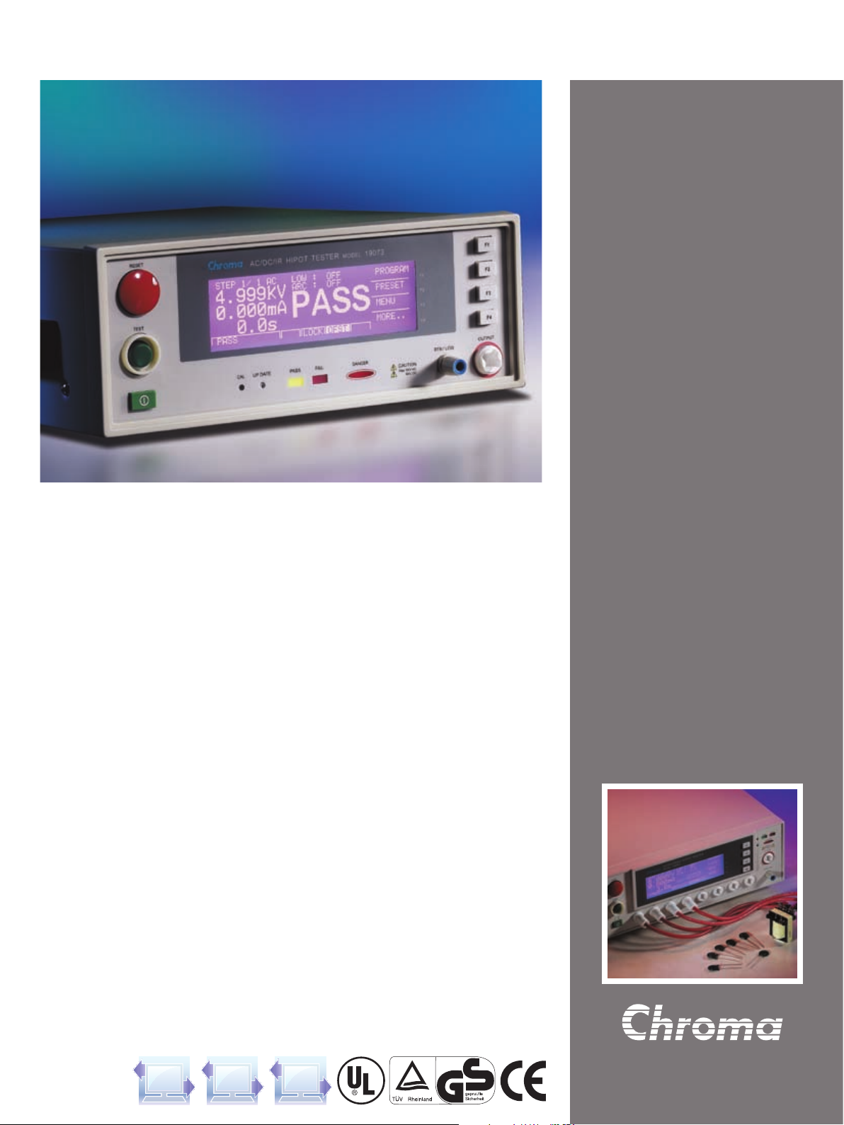
AC/DC/IR HIPOT TESTER
MODEL 19070 & 19050 SERIES
Complete Dielectric Testing Solution
The 19050 seri es elect rical safety tester s are
adv ance d digi tal hip ots wi th load an d lin e
regulation to ensure the measurement integrity.
Mult i-s te p cap ab ility allows users to per form
multipl e test s in a sequence such as AC hipot
followed by IR.
The Chroma Hipot Tester 19050 series provides
3 models for choice. The 19052 is for AC/DC/IR
Hip ot te stin g and in sula tion resi stan ce (I R)
measurements. The 19053 IR measurement is with
8 scan channels, and the 19054 IR measurement
is with 4 scan channels capability into a single
compact unit.
The Chroma Hipot Tester 19070 series provides
2 models for choice. The 19071 is for AC Hipot
testing. The 19073 com bi ne s bot h AC and DC
Hipot with insulation resistance (IR) measurements
into a single compact unit.
Open Short Check (OSC)
The OSC function is used to check whether the
connection is open circuit between instrument
and DUT or breakdown inside DUT before testing
the electrical safety.
Flashover (ARC) Detection
The 19070 series is sensitive enough to monitor
current spikes even if they do not exceed the
maximum trip current level.
Ground Continuity Check
All of the 19050 seri es testers ha ve a gro un d
con ti nui ty ch eck fea tu re to de te rmine th e
resistance, th at is between the ground blade
of power cord and any exposed metal on the
product, is less than 1Ω.
Ground Fault Interrupt (GFI)
GFI is required by the National Elec trical Code
in wet locat ions. Such d evices automati cally
interrupt power when a ground current > 0.5mA
ex is ted fo r more th an a few mi ll i-se conds to
protect users.
Quick Discharge
In DC hipot and IR test the device under test is
discharged back through the HV transformer. This
technique results in a rapid and safe discharge.
AC/DC/IR Hipot Tester
MODEL 19070 SERIES
19050 SERIES
Basic Specifications:
■ AC/DC/IR 3 in 1 hipot tester
■ AC 5kV and DC 6kV output
■ 1kV insulation resistance test
■ Insulation resistance measurement from
1MΩ to 50GΩ
■ Ground continuity check
■ Standard RS-232 interface
Key Features:
■ Open short check(OSC) function
■ GFI shutdown the instrument when
imbalance current > 0.5mA
■ Flashover (ARC) detection
■ Quick discharge of DUT in IR and DC test
■ Pause mode
Others:
■ Large LCD display (240 x 64 dots matrix)
■ UL and TUV approved (*see spec)
■ CE mark
■ Programmable ramp/fall and test time
■ Programmable high/low limit
■ Save/Recall program test function
■ Remote control and interface support
Page 2
TECHNICAL NOTE
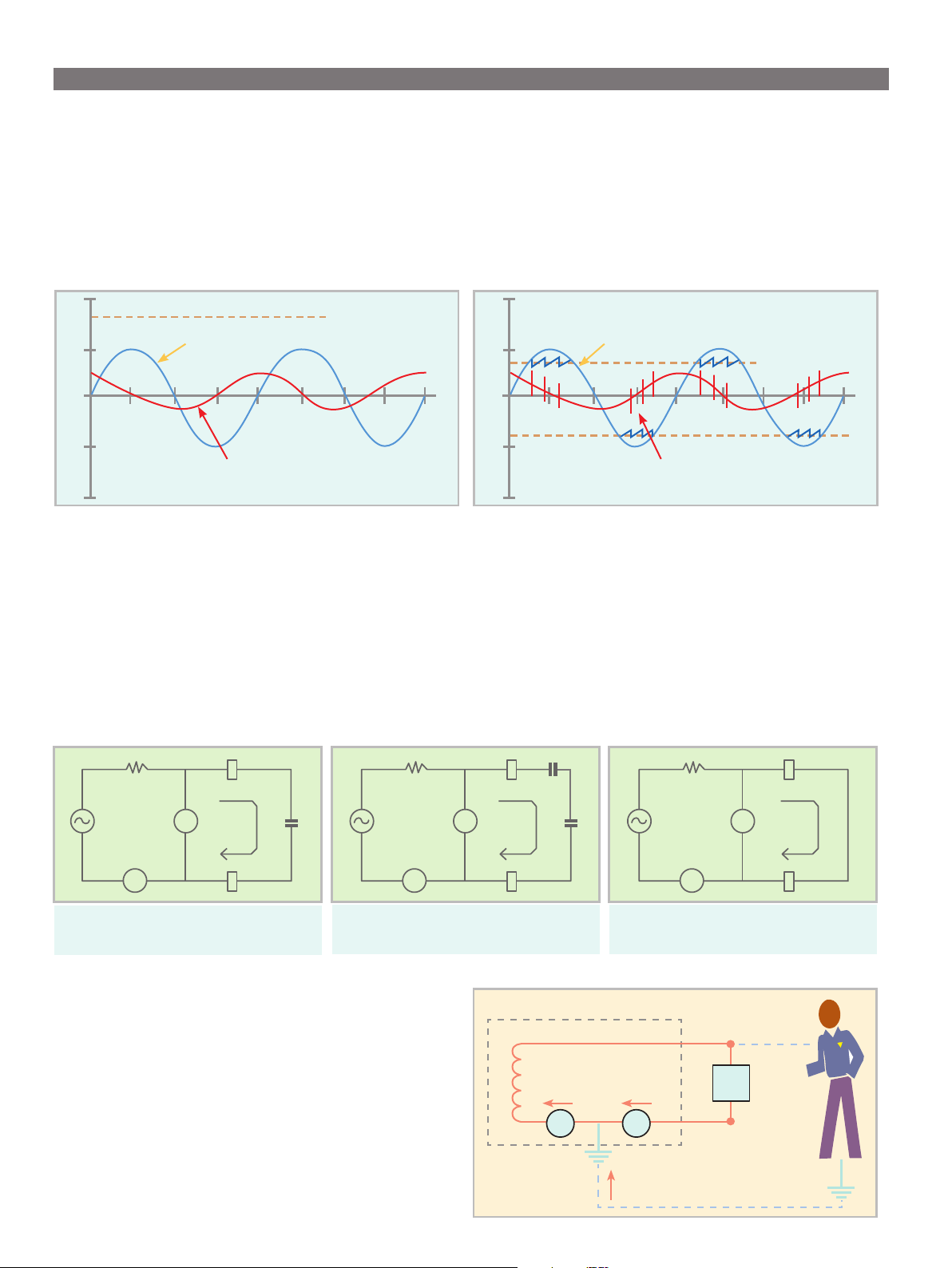
FLASHOVER DETECTION
Fast transient in Voltage or Current occured while Hi-Pot testing is called Electrical Flashover. Normally, in AC line frequency (50Hz/60Hz) or DC Hi-Pot
testing, the leakage current is the same as 50Hz/60Hz or DC (charge current is excepted). As shown in Figure leakage current varies smoothly.
On the other hand, electrical discharge occurred because of poor insulation in material, electrode gap or surface clearance etc., fast transient in leakage
current apparent as shown in gure. This is phenomenon of poor withstanding. Most of Electrical Safety regulations mention the necessity in Withstand
Strength Test. Nevertheless, general Hi-Pot tester detects the RMS value of leakage current only without capability to detect Flashover. Therefore,
FLASHOVER detection function equipped with Hi-Pot tester is necessary.
10
Gap Discharge Voltage
Test Voltage Waveform
0
180 360
Leakage Current (normal capacitive)
-10
Figure 1 : Normal Leakage Current Waveform
10
Test Voltage Waveform
Gap Discharge Voltage
0
180 360
Leakage Current (abnornmal with ashover)
-10
Figure 2 : Leakage Current Waveform when ahover occurred
OPEN/SHORT CHECK (OSC)
O.S.C function is used to check the connection is open or short circuit between instrument and DUT(equipment under test) before the Electrical Safety Test.
If the connection is bad between the instrument and DUT, sometimes like leads or relay oxidation, the judgment is also PASS. In some cases, the DUT is
short before testing. Testing continually leads to our instrument broken because suered the high load current. Therefore, we have to check the open and
short circuit to ensure the test eectively and protect instruments.
Generally, the DUT have capacitive load (Cx) from tens to thousands of pF. If the connection opening, a capacitance will appear and then total capacitive
load is lower than that in normal condition. If the DUT shorting, total capacitive load is higher than that in normal condition. Therefore, we can measure the
value of capactive load to check the contact is good or not.
Hi
V
s
V
µA
Normal Condition
Ground Fault Interrupt (GFI)
The requirement of test environment indicates that test equipment
is equipped with auto interrupt device so that Chroma develops into
Ground Fault Inter rupt (GFI) function. When the current meter A
and A2 detect the difference (i2-i1=iH) between the value i1 and actual
i2 test current over high, this device can cut the power transiently for
protecting human body safety. It is not only compliance with the safety
standard but also more safeguards for test personnel.
Lo
C
x
V
s
µA
If Circuit Opened :
C = Cc*Cx/(Cc+Cx) << C
Hi
V
Lo
C
c
C
x
V
s
V
µA
If Circuit Shorted :
x
C >> C
Hi
Lo
x
Hipot Tester
HV
1
i
2
i
1
Return
A
2
A
1
i
H
DUT
Operator
Page 3

PANEL DESCRIPTION
19073
3
4
1
2 5
20
19053
3
4
1
1. LINE Switch
2. Window Display
3. Stop Button
4. Start Button
5. Function Keys (F1~F4)
6. Calibration Switch
6 23 7 8 9 11 10
2 5 6 7 8
12 23
9. Test Indicator
10. HV Output
11. RTN/LOW
12. 8 channels HV Output
(19053 only)
13. Remote I/O
10 14 11 22 15 19
19 14 13 22 20 17 18
9
10
11
16 15 21
16. RTN/LOW
17. GPIB/Printer Interface (Option)
18. Scan Interface (Option)
19. Fan
20. Remote Interface
21. RS-232 Interface
7. Pass Indicator
8. Fail Indicator
14. LINE Voltage Selector
15. Power Cord Receptacle
22. Continuity Test O/P
23. Update Switch
APPLICATION
■ Production test of appliances, instruments and information technology equipment in accordance with UL, IEC, TUV and other standards such
as EN 60335, EN 60950, EN 61010, CSA C22.2 No.1010.1, UL 3111 and UL 1950
■ Transformer electrical safety test
■ Electric motor safety test
■ Various electronic components tests
ORDERING INFORMATION
19071 : AC Hipot Tester
19073 : AC/DC/IR Hipot Tester
19073 : AC/DC/IR Hipot Tester with RS485
A190701 : Remote Control Box
A190702 : 40kV Test Probe
A190344 : HV Gun (SP02)
A190706 : 19" Rack Mount Kit
19052 : Hipot Tester (AC/DC/IR)
19053 : Hipot Tester (AC/DC/IR/ 8CH SCAN)
19054 : Hipot Tester (AC/DC/IR/ 4CH SCAN)
A190512 : Auto Control TR. Scan Box
A190508 : GPIB Interface
A190344 : HV Gun (SP02)
A150517 : 19" Rack Mount Kit
Page 4

SPECIFICATIONS
Model 19071 19073 19052 19053 19054
Mode AC AC/DC/IR AC/DC/IR AC/DCV/IR/SCAN ACV/DCV/IR/SCAN
Scanner Unit - - - 8 ports,±phase 4 ports,±phase
Withstanding Voltage Test
Output Voltage AC : 0.05 ~ 5kV, DC : 0.05 ~ 6kV
Load Regulation 1% of setting + 5V
Voltage Resolotion 2V
Voltage Accuracy 1% of setting + 5 count
Cuto Current AC : 0.1~20mA,DC : 0.01 ~ 5mA AC : 0.1 ~ 30mA, DC : 0.01 ~ 10mA
Current Resolution AC : 1µA, DC : 0.1µA
Current Accuracy 1% of setting + 5 count
Output Frequency 50Hz / 60Hz
Test Time 0.3 ~ 999 sec., continue
Ramp Time 0.1 ~ 999 sec., o
Fall Time 0.1 ~ 999 sec., o
Dwell Time 0.1 ~ 999 sec., o
Waveform Sine wave
Insulation Resistance
Output Voltage - DC : 0.05 ~ 1kV
Voltage Resolution - 2V
Voltage Accuracy - 1% Reading + 1% Full Scale
IR Range - 1MΩ~50GΩ 1MΩ~10GΩ
1.00MΩ~ 25.00MΩ -
22.0 MΩ~250.0MΩ -
≥ 500V
Resistance
Accuracy
0.220GΩ~1.000GΩ - ± (5% of reading + 5% of full scale)
1.000GΩ~2.500 GΩ - ± (10% of reading + 2% of full scale)
2.20GΩ~10.00GΩ - ± (15% of reading + 5% of full scale)
10.00GΩ~50.00GΩ - ± (15% of reading + 1% of scale) -
0.10 MΩ~25.00MΩ -
≤ 500V
22.0MΩ~250.0MΩ -
0.220 GΩ~1.000GΩ - ± (10% of reading + 5% of full scale)
Flashover (ARC) Detection
Setting Mode Programmable setting
Detection Current AC : 1mA ~ 15mA, DC : 1mA ~ 5mA AC : 1mA ~ 15mA, DC : 1mA ~ 10mA
Secure Protection Function
Fast Output Cut-o 0.4ms after NG happen
Ground Fault Interrupt 0.5mA ±0.25mA AC, ON/OFF
Panel Operation Lock Present password
Continuity Check 1Ω ± 0.2Ω, ON/OFF
GO/NG Judgment Window
Indication, Alarm GO : Short sound, Green LED ; NG : Long sound, Red LED
Data Hold Least tests data memories
Memory Storage 60 steps in 60 groups 500 steps in 99 groups
Remote & Interface
Remote control Input : Start, Stop, Interlock (at 11 pin terminal block only) ; Output : Under test, Pass, Fail
Communication Interface RS485 (Option) RS232 (Standard), GPIB (Option).
General
Operation Environment Temperature : 0°C~40°C, Humidity : 15% to 95% R.H@≤40°C
Power Requirements 100V/120V/220V/240V (AC ±10%), 50/60Hz
Power Consumption 300W 500W
Dimension (W x H x D) 270 x 105 x 350 mm 320 x 105 x 400 mm
Weight Approx.12 KG Approx.15 kg
Certication UL,TUV,CE UL,TUV,CE CE UL,TUV,CE
*All specifications are subject to change without notice.
± (5% of reading + 2% of full scale)
± (10% of reading + 2% of full scale)
Developed and Manufactured by :
CHROMA ATE INC.
致茂電子股份有限公司
HEADQUARTERS
No. 66, Hwa-Ya 1st Rd.,
Hwa-Ya Technology Park,
Kuei-Shan Hsiang,33383
Taoyuan County, Taiwan
Tel: +886-3-327-9999
Fax: +886-3-327-8898
http://www.chromaate.com
E-mail: info@chromaate.com
CHINA
CHROMA ELECTRONICS
(SHENZHEN) CO., LTD.
8F, No.4, Nanyou Tian An
Industrial Estate, Shenzhen,
China PC: 518052
Tel: +86-755-2664-4598
Fax: +86-755-2641-9620
JAPAN
CHROMA JAPAN CORP.
472 Nippa-cho, Kouhoku-ku,
Yokohama-shi, Kanagawa,
223-0057 Japan
http://www.chroma.co.jp
E-mail: info@chromaate.com
U.S.A.
CHROMA SYSTEMS
SOLUTIONS, INC.
25612 Commercentre Drive,
Lake Forest, CA 92630-8830
Tel: +1-949-600-6400
Fax: +1-949-600-6401
Toll Free: +1-866-600-6050
http://www.chromausa.com
E-mail: sales@chromausa.com
Distributed by:
EUROPE
CHROMA ATE EUROPE B.V.
Morsestraat 32, 6716 AH Ede,
The Netherlands
Tel: +31-318-648282
Fax: +31-318-648288
http://www.chromaeu.com
E-mail: sales@chromaeu.com
Worldwide Distribution and Service Network
19070+19050-E-201108-1000
 Loading...