

Page 1
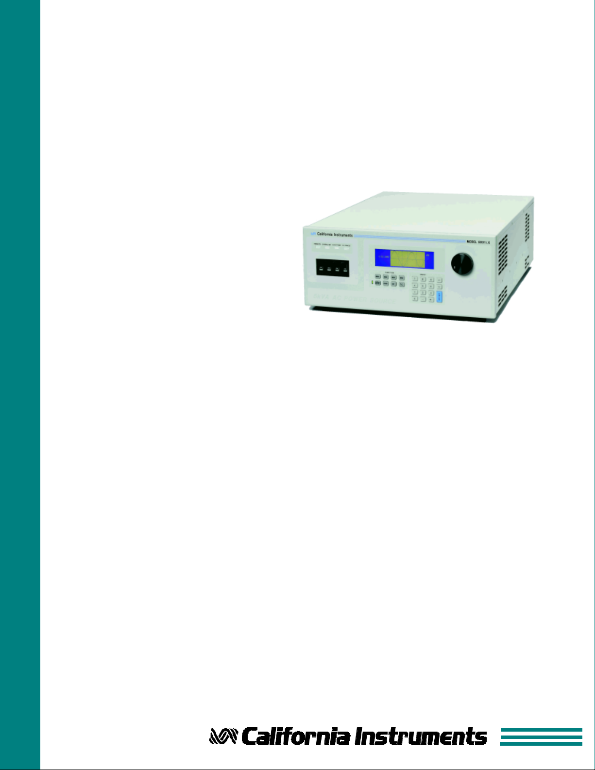
Power Source / Analyzer
n Single Box AC Power System.
Combines AC & DC power source, digital
scope and power analyzer in one
instrument
n DC Output Capability
Use same instrument for DC output
n 3000 VA to 15000 VA AC Power Levels
Match power source and cost to
application requirements
n Arbitrary Waveform Generator
Test products for harmonics
susceptibility
n Built-in DSP based Power Analyzer
Performs voltage and load current
analysis on all phases
n Programmable Output Impedance
Simulate real-world line conditions
n High Crest Factor Capability
Drives a wide variety of
non-linear loads
n CE Marked
Safe, reliable and consistent operation
AC and DC Power Systems
iX Series
AC and DC Power Source and
Analyzer Combination
Integrated System
The iX Series represents a new
type of AC and DC power source that
addresses increasing demands on
test equipment to perform more
functions at a lower cost. By
combining a flexible AC power source
with a high end power analyzer, the
iX Series systems are capable of
handling applications that would
traditionally have required multiple
instruments.
The sleek integrated approach of
the iX Series avoids the cable clutter
that is commonly found in AC test
setups. All connections are made
internally and the need for external
digital multimeters, power harmonics
analyzer and current shunts or
clamps is completely eliminated.
Using a state of the art digital
signal processor in conjunction with
precision high resolution A/D
converters, the iX Series provides
more accuracy and resolution than
can be found in some dedicated
harmonic power analyzers. Since
many components in the iX Series
are shared between the AC source
and the power analyzer, the total cost
of the integrated system is less than
the typical cost of a multiple unit
system.
Easy To Use Controls
The iX Series is completely
microprocessor controlled and can be
operated from an easy to use front
panel keypad. Functions are grouped
logically and are directly accessible
from the keypad. This eliminates the
need to search through various levels
of menus and or softkeys.
A large analog control knob can
be used to quickly slew output
parameters. This knob is controlled
by a dynamic rate change algorithm
that combines the benefits of precise
control over small parameter changes
with quick sweeps through the entire
range.
Applications
With precise output regulation
and accuracy, high load drive current,
multi or single phase output mode
and built-in power analyzer
measurement capabilities, iX Series
AC and DC source/analyzers address
all application areas for AC and DC
power testing. Additional features like
line distortion simulation (LDS),
arbitrary waveform generation and
programmable output impedance
address requirements for product
quality and regulatory compliance
testing.
Waveform Acquisition
Voltage and current waveform
data can be acquired on all three
phases and shown on the LCD
display. Applications include inrush
current measurement and load
characterization.
Page 2
iX Series - Multi-Function and Multi-Use
Product Evaluation and Test
Increasingly, manufacturers of electronic
equipment and appliances are required to fully
evaluate and test their products over a wide range of
input line conditions. The built-in Line Distortion
Simulation and load measurement system combines
all needed source and measurement functions in an
easy to use system.
Avionics
With an output frequency range to 500 Hz, the
iX Series is well suited for aerospace applications.
Precise frequency control and accurate load
regulation are key requirements in these
applications. The standard IEEE-488 control
interface and SCPI command language provide for
easy integration into existing ATE systems. Since
the iX Series can eliminate the need for three or four
items of instrumentation and only occupies 7 inches
of rack space, cost and space savings provide a
rapid return on investment. Instrument drivers for
popular programming environments such as National
Instruments LabView are available to speed up
system integration.
High Crest Factor
With a crest factor of up to 5:1, the iX Series AC source /
analyzers can drive difficult non-linear loads with ease. Since
many modern products use switching power supplies, they have
a tendency to pull high repetitive peak currents. If the AC power
source used to test these products has insufficient peak current
drive capability, the waveform exhibits voltage distortion. The
5001iX can deliver up to 110 Amps of repetitive peak current (low
range) to avoid this problem.
Remote Control
Standard IEEE-488 and RS232C remote control interfaces
allow programming of all instrument functions from an external
computer. The popular SCPI command protocol is used for
programming. Drivers for several popular instrumentation
programming environments are available to facilitate systems
integration of the iX Series.
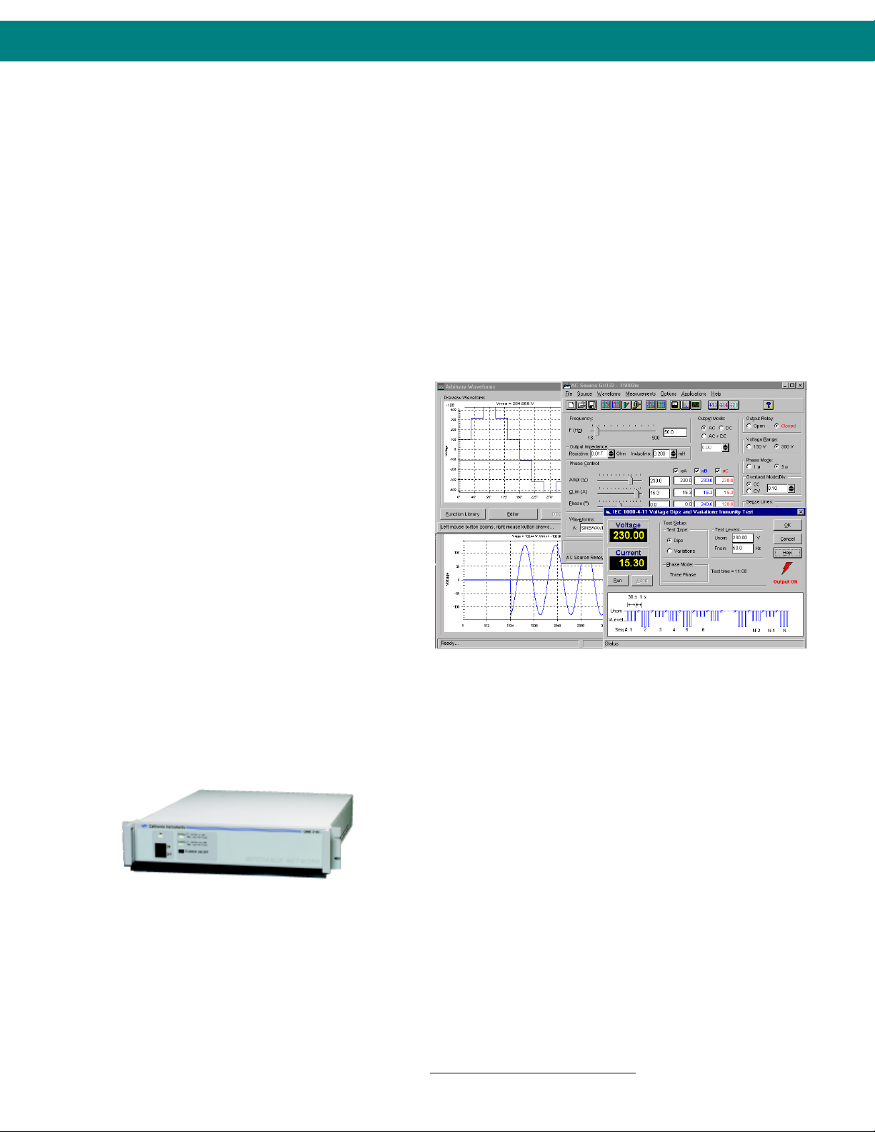
Regulatory Testing
As governments are moving to enforce product
quality standards, regulatory compliance testing is
becoming a requirement for a growing number of
manufacturers. The iX Series is designed to meet
AC source requirements for use in Euronorm IEC1000 compliance testing. For flicker testing, the
programmable output impedance capability of the
3001iX, 5001iX and 15003iX can be used to create
the required IEC 725 reference impedance.
Multi-Box Configurations
For high power applications, two or three 5001iX
chassis can be combined to provide 10 to 15 kVA of
single phase power.
Mode-iX Option
A 15003iX three phase configuration can be
ordered with the Mode-iX option. This option allows
automatic switching between single or three phase
output mode. In single phase mode, all current is
available on phase A. The Mode-iX option switches
the output from all three 5001iX amplifiers to a
single output connector. Without the Mode-iX
option, 15003iX systems are configured for three
phase operation.
GUI application program screens for AC Source control and
measurements.
Application Software
Windows® application software is provided free of charge with
the iX Series1. This software provides easy access to the iX
Series’ many powerful capabilities without the need to develop
any custom code. The following functions are available through
this GUI program:
• Steady state output control (all parameters)
• Create, run, save, reload and print transient programs
• Generate and save harmonic waveforms
• Generate and save arbitrary waveforms
• Download data from a digital storage oscilloscope
• Measure and log standard measurements
• Capture and display Voltage and Current waveforms
• Measure, display, print and log harmonic voltage and current
measurements
• Run IEC 1000-4-11, IEC 1000-4-14 and IEC 1000-4-28 test
programs
• Display IEEE-488 or RS232C bus traffic to and from the AC
Source to help you develop your own test programs
1
Requires PC running Windows Win95/98
Recommended Pentium 233 MHz or better.
®
or WinNT 4.0®.
Page 3
iX Series - Waveform Generation
programmed rate.
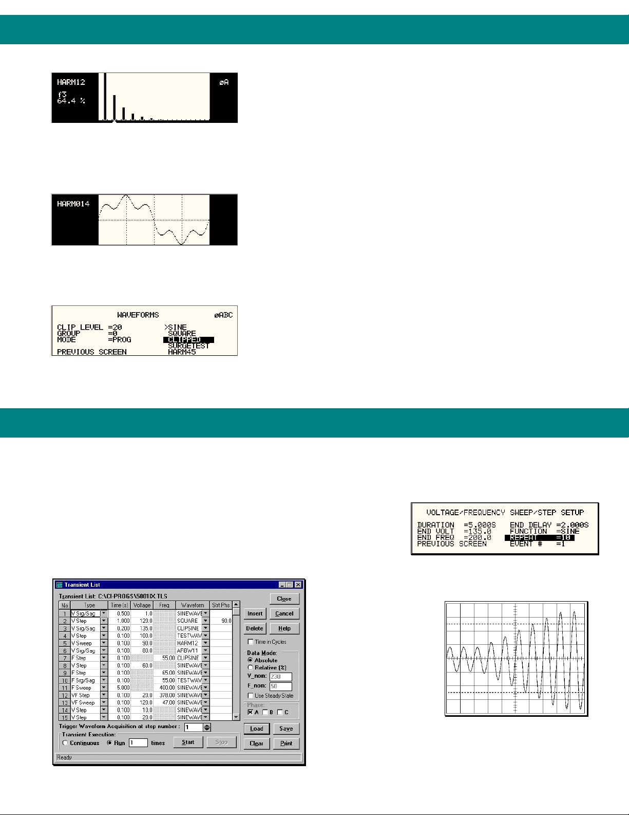
Harmonic Waveform Generation
Using the latest DSP (Digital Signal Processing) technology, the iX Series
controller is capable of generating harmonic waveforms to test for harmonics
susceptibility of a unit under test. Included is a Graphical User Interface
program that can be used to define harmonic waveforms by specifying
th
Harmonic waveform, Fund., 3rd, 5th, 7th, 9th,11
and 13th.
Preview custom waveforms on screen before use
Two hundred user defined waveforms.
amplitude and phase for up to 50 harmonics. The waveform data points are
generated and downloaded by the GUI to the AC source through either the
IEEE-488 or RS232C bus and remain in nonvolatile memory. Up to 200
waveforms can be stored and given a user defined name for easy recall.
The three phase configuration iX Series offers independent waveform
generation on each phase allowing three phase anomalies to be programmed.
It also allows simulation of unbalanced harmonic line conditions.
Arbitrary Waveform Generation
Using the provided GUI program or custom software, the user also has the
ability to define arbitrary AC waveforms. The arbitrary waveform method of data
entry provides an alternative method of specifying AC anomalies by providing
specific waveform data points. The GUI program provides a catalog of custom
waveforms and also allows real-world waveforms captured on a digital
oscilloscope to be downloaded to one of the many AC source’s waveform
memories.
Arbitrary waveform capability is a flexible way of simulating the effect of
real-world AC power line conditions on a unit under test in both engineering and
production environments.
iX Series - Transient Generation
The iX Series controller has a powerful AC and DC transient generation system that allows complex sequences of
voltage, frequency and waveshapes to be generated. This further enhances the iX’s capability to simulate AC line
conditions or DC disturbances. When combined with the multiphase arbitrary waveform capabilities, the AC and DC output
possibilities are truly exceptional. In three phase iX system configurations,
transient generation is controlled independently yet time synchronized on all
three phases. Accurate phase angle control and synchronized transient list
execution provide unparalleled accuracy in positioning AC output events.
Transient programming is easily accomplished from the front panel where
clearly laid out menu’s guide the user through the transient definition process.
The front panel provides a convenient listing of the
programmed transient sequence and allows for transient
execution Start, Stop,
Abort and Resume
operations. User defined
transient sequences can
be saved to non-volatile
memory for instant recall
and execution at a later
time.
The included
Transient List Data Entry in GUI program
Graphical User Interface
program supports transient
definitions using a
spreadsheet-like data
entry grid. A library of frequently used transient programs can
be created on disk using this GUI program.
Voltage sweep transient causes
output voltage to change at a
Page 4

iX Series - Measurement and Analysis
The iX Series is much more than a programmable AC and DC power source. It also
incorporates an advanced digital signal processor based data acquisition system that
continuously monitors all AC source and load parameters. This data acquisition system
forms the basis for all measurement and analysis functions. These functions are
accessible from the front panel and the remote control interface.
Conventional Measurements
Common AC and DC
measurement parameters are
automatically provided by the data
Measurement data for a single phase.
Measurement data for all three phases.
Absolute amplitude bar graph display of current
harmonics with cursor positioned at the fundamental.
Voltage harmonic measurement table display in
absolute values.
Acquired Current waveform
Acquired Voltage waveform
acquisition system. These values are
displayed in numeric form on the front
panel LCD display. The following
measurements are available:
Frequency, V
Real Power, VA Power, Power Factor.
, I
,, Ipk, Crest Factor,
rms
rms
Harmonic Analysis
The iX Series provides detailed
amplitude and phase information on up
to 50 harmonics of the fundamental
voltage and current for either one or
three phases. Harmonic content can be
displayed in both tabular and graphical
formats on the front panel LCD for
immediate feedback to the operator.
Alternatively, the included GUI program
can be used to display, print and save
harmonic measurement data. Total
harmonic distortion of both voltage and
current is calculated from the harmonic
data.
Waveform Acquisition
The measurement system is
based on real-time digitization of the
voltage and current waveforms using a
4K deep sample buffer. This time
domain information provides detailed
information on both voltage and current
waveshapes. Waveform acquisitions
can be triggered at a specific phase
angle or from a transient program to
allow precise positioning of the
captured waveform with respect to the
AC source output.
The front panel LCD displays captured
waveforms with cursor readouts. The
included GUI program also allows
acquired waveform data to be
displayed, printed and saved to disk.
California
Instruments
Total Customer
Satisfaction is the goal
of all California
Instruments’ employees.
It is the driving force
behind everything we
do. This not only affects
the product that you
purchase from California
Instruments, but
everything about your
interface with the
company. Our
applications engineers
are ready to assist you
with your AC power
application. With over
35 years of experience
designing and building
precision AC power
supplies, chances are
we can meet your needs
and exceed your
expectations. The same
dedication to customer
satisfaction you will find
in our applications group
also permeates our
modern manufacturing
facility where our
products are carefully
built. No unit leaves our
factory without being
thoroughly tested to
ensure quality, reliability
and conformance to
specifications.
CE Mark
The iX Series power
sources (-400 models)
have been fully tested
for compliance with
1997 CE Mark
requirements. This
allows these products to
be used throughout the
European Economic
Community.
Page 5

iX Series - Specifications
1
Operating Modes
AC, DC or AC + DC
AC Mode Output
Frequency
16.00 Hz - 500.0 Hz
Power
Maximum AC power per phase
at full scale voltage:
Model: Power
3001iX
5001iX
10001iX
15001iX
15003iX
(with mode-iX)
Power Factor
0 to unity at full output VA
AC Voltage
Ranges User selectable
voltage range pairs:
Range: Low High
Max Vrms 135 V 270 V
Max Vrms 150 V 300 V
Load Regulation
± 0.5% DC to 100 Hz
± 0.6 % 100 Hz to 500 Hz in high
voltage range
± 2.2 % 100 Hz to 500 Hz in low
voltage range
Line Regulation < ± 0.1% for 10
% line change
Output Noise < 250 mV
(20 kHz to 1 MHz) < 500 mV
Harmonic Distortion (linear load)
Less than 1% from 16 - 66 Hz
Less than 2% at 400 Hz
DC Offset < 20 mV
External Modulation
depth: 0 - 10 %
Isolation Voltage
300 V
output to chassis
rms
AC Current
Peak Repetitive AC Current
Model High
3001iX
5001iX
10001iX
15001iX
15003iX 1ø
3ø 96.0 110.0
3000 VA
5000 VA
10000 VA
15000 VA
5000 VA/ø 3ø
15000 VA/ø 1ø
typ.
rms
max.
rms
Low
range
96.0 110.0
96.0 110.0
192.0 220.0
288.0 330.0
288.0 330.0
range
AC Current
Steady State AC Current
Model 270 V
range
3001iX
5001iX
10001iX
15001iX
15003iX 1ø
11.1 22.2
18.5 37.0
37.0 74.0
55.5 111.0
55.5 111.0
3ø 18.5 37.0
135 V
range
Programming Accuracy
Voltage (rms): ± 0.5 % of range,
16 to 400 Hz
Frequency: ± 0.01 % of
programmed value.
Current Limit: - 0 % to + 7 % of
programmed value + 0.5 A.
Phase: < 1.5° with
balanced load @ 50/60 Hz.
Programming Resolution
Voltage (rms): 100 mV
Model 300 V
range
3001iX
5001iX
10001iX
15001iX
15003iX 1ø
10.0 20.0
16.7 33.3
33.3 66.7
50.0 100.0
50.0 100.0
3ø 16.7 33.3
150 V
range
Frequency:
0.01 Hz from 16 Hz to 81.91 Hz
0.1 Hz from 82.0 Hz to 500.0 Hz
Current Limit:
0.1 A for 5001iX and 15003iX.
1.0 A for 10001iX and 15001iX.
Phase: 0.1°
Standard Measurements (5001iX)
Parameter Range Accuracy* (±) Resolution
AC Measurements
Frequency 16.00 - 500.0 Hz 0.01% + 0.01 Hz 0.01 Hz
< 100 Hz 100 - 500
Hz
RMS Voltage 0 -330 V 50 mV 100 mV 10 mV
RMS Current 0 - 40 A 50 mA 100 mA 1 mA
Peak Current 0 - 119 A 50 mA 100 mA 1 mA
Crest Factor 0.000 - 6.000 0.05 0.05 0.01
Real Power 0 - 6 kW 5 W 5 W 1 W
Apparent
Power
Power Factor 0.00 - 1.00 0.01 0.01 0.01
DC Measurements
DC Voltage 0 - 420 V 500 mV 10 mV
DC Current 0 - 120 A 500 mA 1 mA
Power 0 - 6 kW 50 W 1 W
* Measurement system bandwidth = DC to 19.5 kHz. Accuracy specifications are valid above 100
counts. Current and Power Accuracy specifications are times two for 10001iX and times three for
15001iX. For 10001iX and 15001iX, resolution decreases by factor of 10, ranges for current and
power increases by factor of three.
0 - 6 kVA 10 VA 20 VA 1 VA
Harmonics Measurements
Parameter Range Accuracy* (±) Resolution
Frequency
Fundamental 16.00-500.0 Hz 0.01% + 0.01 Hz 0.01 Hz
Harmonics 32.00 Hz - 19.5 kHz 0.01 Hz
Phase 0.0 - 360.0° 2° typ. 0.5°
Voltage Fundamental 250 mV 10 mV
Harmonics 2 - 50 0.1% + 250 mV+0.1% /1 kHz 10 mV
Current Fundamental 50 mA 10 mA
Harmonics 2 - 50 0.1% + 50 mA +0.1% /1 kHz 10 mA
* Accuracy specifications are valid above 100 counts. Accuracy specifications are times three for
three phase mode. Harmonics frequency range in three phase mode is 32 Hz - 6.67 kHz. Resolution
decreases by factor of 10 for 10001iX and 15001iX.
*
Page 6

iX Series - Specifications
1
Output Relay
Push button controlled or bus
controlled output relay
Output impedance
Programmable Z on 3001iX,
5001iX and 15003iX for 50 Hz
fundamental
Resistive:
range 17 - 1000 mΩ
resolution 4 mΩ
accuracy 2 % FS
Inductive:
range 230 - 1000 µH
resolution 4 µH
accuracy 2 % FS
DC Mode Output
Maximum DC power at full scale
of DC voltage range:
Model: Power
3001iX
5001iX
10001iX
15001iX
15003iX
Voltage Ranges
User selectable voltage range
combinations:
Range: High Low
270 V 135 V
300 V 150 V
Load Regulation see AC mode
Line Regulation see AC mode
Output Noise < 250 mV
(20 kHz to 1 MHz) < 500 mV
Max. DC Current Capability
Maximum DC current in lowest
DC range pair:
Model 270
range
3001iX
5001iX
10001iX
15001iX
15003iX 1ø
Current Limit Programmable
from 0 A to max. current for
selected range.
27.75 55.5
27.75 55.5
3ø 9.25 18.5
1500 W
2500 W
5000 W
7500 W
2500 W/ø 3ø
7500 W/ø 1ø
Typ
rms
Max
rms
135
range
5.65 11.1
9.25 18.5
18.5 37.0
AC + DC Mode Output
Power
Full AC power if DC component
is less than 20 % of full scale
voltage. Full DC power if DC
component is above 20 %.
IEEE-488 Interface
System
Non Volatile Memory storage
16 complete instrument setups
200 user defined waveforms
Waveforms
Waveform Types
• Sine
• Square
• Clipped Sine, 0 - 20 % THD
• User defined
User defined waveform storage
Four groups of 50 user defined
arbitrary waveforms of 1024
points for a total of 200. One
group can be active at a time.
Transient Programming
Transient Types
Voltage: drop, step, sag, surge,
sweep
Frequency: step, sag, surge,
sweep
Voltage and Frequency: step,
sweep
Transient List Parameters:
Voltage, Frequency, Time or
cycles, Slew rate, Waveform
shape, Phase angle, Repeat
Transient lists storage
up to 32 transient steps per list
Time resolution 1 msec
Time range 1 msec - 9999 sec
Maximum slew rate
50 µsec for 10% to 90% of full
scale change into resistive load
Waveform Acquisition
Channels
Voltage and Current for each
phase.
Memory Depth
4096 samples/channel.
Maximum Sample Rate
39.0625 Ks/s.
Triggering
Auto, Phase, Transient.
Trigger Delay
Pre-trigger 0 - 104 msec 1ø
0 - 312 msec 3ø
Post-trigger 0 - 1000 msec.
Display
Front panel Graphics Display
with cursors.
Bus Interface
Full bus access to waveform
acquisition system.
IEEE-488 (GPIB) talker listener.
Subset:
AH1, C0, DC1, DT1, L3, PP0,
RL2, SH1, SR1, T6
IEEE-488.2 SCPI Syntax
RS232C Interface
9 pin D-shell connector
Handshake: CTS, RTS
Databits: 7,8
Stopbits: 1,2
Baud rate: 9600, 19200,
38400
IEEE-488.2 SCPI Syntax
Supplied with RS232C cable
System Interface
Inputs: Remote shutdown
External Sync
Outputs: Function Strobe
AC Input
Voltage
Model 3001iX:
187 - 264 VAC,(L-N, 1 Phase)
All other models:
Standard:
187 - 264 VAC,(L-L, 3 Phase)
Option -400:
360 - 528VAC,(L-L, 3 Phase)
(Input range must be specified
when ordering)
Current
Input Line Current (per phase)
Model: 187-
264V
3001iX
5001iX
10001iX
15001iX
15003iX
Inrush Current per chassis
< 14 A rms. / 84 A
@ 187-264 V
< 8 A rms. / 36 A
@ 360-528 V
Line Frequency: 47 - 63 Hz
Efficiency: 75 % typical
Power Factor: 0.6 typical
Hold-up Time: At least 10 ms
30 A N/A
24 A 12 A
48 A 24 A
72 A 36 A
72 A 36 A
peak
peak
Remote Control
Note 1: Specifications are warranted over an ambient temperature range of 25°± 5° C.
Unless otherwise noted, specifications are per phase for a sinewave with a resistive
load and apply after a 30 minute warm-up period.
360528V
for 200 µs
for 400 µs
Page 7

iX Series - Specifications
Protection
Over Load
Constant Current or Constant
Voltage mode
Over Temperature
Automatic shutdown
Regulatory
IEC1010, CSA22.2 No. 231,
EN50081-2, EN50082-2 CE
EMC and Safety Mark
requirements
RFI Suppression
CISPR 11, Group1 , Class A
Rear Panel Connectors
• AC Input terminal block with cover
• AC output terminal block with
cover
• IEEE-488 (GPIB) connector
• 9 pin D-Shell RS232C connector*
• Remote voltage sense terminal
block
• System Interface Connector
(*RS232 DB9 to DB9 cable supplied)
Physical
Dimensions per 5001iX unit
Height : 7” (178 mm)
Width : 19” (483 mm)
Depth : 24” (610 mm)
(Depth includes rear panel connectors)
Weight per 5001iX chassis
61 lbs / 28 Kg net
80 lbs / 36 Kg shipping
Vibration and Shock
Designed to meet NSTA project
1A transportation levels
Air Intake/Exhaust
Forced air cooling, side air
intake, rear exhaust
Operating Humidity
0 to 95 % RAH, non
condensing.
Operating Temperature
0 to 40° C
Storage Temperature
-40 to +85° C
Ordering Information
Model Line input
3001iX 208 VAC L-L, 1ø
5001iX 208 V
5001iX -400 400 VAC L-L, 3ø
10001iX 208 VAC L-L, 3ø
10001iX -400 400 VAC L-L, 3ø
15001iX 208 VAC L-L, 3ø
15001iX -400 400 VAC L-L, 3ø
15003iX 208 VAC L-L, 3ø
15003iX -400 400 VAC L-L, 3ø
Supplied with
• User manual
• SCPI programming manual
• Rack mount handles
• Windows® Graphical User
Interface software
• RS232C Serial cable
Options
-Mode-iX Switches between 1
and 3 phase modes,
for 15003iX only.
-704 Mil Std 704D test
firmware
-160 RTCA/DO-160C test
firmware
-411 IEC 1000-4-11 test
firmware
-413 IEC 1000-4-13
Harmonics and
Interharmonics test
-EOS-1 IEC 1000-4-11
Electronic Output
Switch (1 phase)
-EOS-3 IEC 1000-4-11
Electronic Output
Switch (3 phase)
-LNS Line Sync.
Synchronizes output
frequency to line
input frequency
-RMS Rack mount slides
AC
L-L, 3ø
Customer Support
For technical support and
service, or to discuss your AC power
application needs, contact California
Instruments Corp. or your local
3001iX/5001iX Dimensions - single chassis
9689 Towne Centre Drive, San Diego CA, 92121-1964 (858) 677-9040 FAX : (858) 677-0940
Copyright 1997, California Instruments Corp. Specifications subject to change without notice Printed in the USA. iXSDS 3/98
representative.
Contact California Instruments:
Toll-Free: 800-4AC-POWER
800-422-7693
FAX: 858-677-0940
Email: sales@calinst.com
Web page: http://www.calinst.com
 Loading...