

Page 1
Model 100W1000B,
(
)
M1 through M6
100 Watts CW
1MHz–1000MHz
The Model 100W1000B is a portable, self-contained, air-cooled, broadband, completely solid-state amplifier designed
for applications where instantaneous bandwidth, high gain and linearity are required. Push-pull circuitry is utilized in all
high power stages in the interest of lowering distortion and improving stability. The Model 100W1000B, when used with
a sweep generator, will provide a minimum of 100 watts of RF power.
The Model 100W1000B is equipped with a Digital Control Panel (DCP) which provides both local and remote control of
the amplifier. The DCP uses a digital display, menu assigned softkeys, a single rotary knob, and four dedicated switches
(POWER, STANDBY, OPERATE and FAULT/RESET) to offer extensive control and status reporting capability. The display
provides operational presentation of Forward Power and Reflected Power plus control status and reports of internal
amplifier status. Special features include a gain control, internal/external automatic level control (ALC) with front panel
control of the ALC threshold, pulse input capability and RF output level protection. Also included is an internal RF detector
which provides an output for use in self-testing or operational modes. Protection is provided by DC current level sensing
and individual fusing of all output stages.
All amplifier control functions and status indications are available remotely in GPIB / IEEE-488 and RS-232 format. The
buss interface connector is located on the back panel and positive control of local or remote operation is assured by a
keylock on the front panel of the amplifier.
Housed in a stylish, contemporary bench top enclosure, the Model 100W1000B provides readily available RF power for
typical applications such as RF susceptibility testing, antenna and component testing, watt meter calibration, and as a
driver for frequency multipliers and higher power amplifiers. A safety interlock can be implemented via a rear panel
connector.
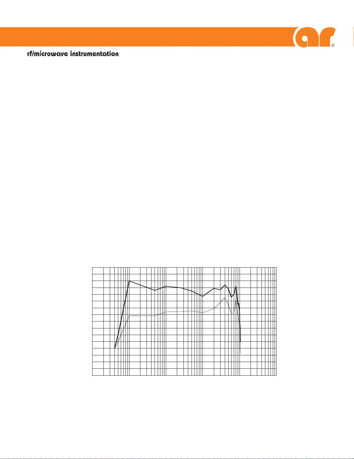
100W1000B TYPICAL POWER OUTPUT
160
140
120
100
80
WATTS
60
40
20
0
0.1
LINEAR @ 1dB COMPRESSION
1 10 100 1000 10000
LINEAR @ 3dB COMPRESSION
FREQUENCY
MHz
012907
160 School House Road Souderton, PA 18964-9990 • 215-723-8181 • www.ar-worldwide.com Page 1 of 2
Page 2

RATED OUTPUT POWER ...............................................100 watts
INPUT FOR RATED OUTPUT ..........................................1.0 milliwatt maximum
POWER OUTPUT @ 3dB compression
Nominal ................................................................123 watts
Minimum ...............................................................100 watts
POWER OUTPUT @ 1dB compression
Nominal ................................................................95 watts
Minimum ...............................................................75 watts
FLATNESS.....................................................................±2.0 dB maximum
1.5 dB typical
±0.8 dB with internal leveling
FREQUENCY RESPONSE ...............................................1-1000 MHz instantaneously
GAIN (at maximum setting) ...........................................50 dB minimum
GAIN ADJUSTMENT (continuous range).........................18 dB minimum
(4096 steps remote)
INPUT IMPEDANCE.......................................................50 ohms, VSWR 2.0:1 maximum
OUTPUT IMPEDANCE ...................................................50 ohms nominal
MISMATCH TOLERANCE * ............................................Will operate without damage or oscillation with any magnitude and phase of
MODULATION CAPABILITY...........................................Will faithfully reproduce AM, FM, or pulse modulation appearing on the input
HARMONIC DISTORTION.............................................Minus 20 dBc maximum at 80 watts
THIRD ORDER INTERCEPT POINT ..................................58 dBm typical
RF POWER DISPLAY ......................................................0-200 watts
PRIMARY POWER (user must specify) ..............................90 - 264 VAC
40/400Hz, single phase
1200 watts maximum
CONNECTORS
RF..........................................................................See Model Configurations
REMOTE INTERFACES
IEEE-488.............................................................24 pin female
RS-232 ...............................................................9 pin Subminiature D (female)
ALC & PULSE .........................................................Type BNC on front panel
SAFETY INTERLOCK .....................................................15 pin Subminiature D
COOLING....................................................................Forced air (self contained fans)
* See Application Note #27
MODEL NUMBER RF INPUT RF OUTPUT WEIGHT SIZE (W x H x D)
100W1000B Type N female on front panel Type N female on front panel 40 Kg (88 lbs) 50.3 x 24.9 x 53.0 cm
100W1000BM1 Type N female on rear panel Type N female on rear panel 40 Kg (88 lbs) 50.3 x 24.9 x 53.0 cm
100W1000BM2 Same as 100W1000B with enclosure removed for rack mounting 30 Kg (66 lbs) 48.3 x 22.2 x 53.0 cm
100W1000BM3 Same as 100W1000BM1 with enclosure removed for rack mounting 30 Kg (66 lbs) 48.3 x 22.2 x 53.0 cm
100W1000BM4 Type N on front panel. Type N on rear panel. 40 Kg (88 lbs) 50.3 x 24.9 x 53.0 cm
100W1000BM5 Same as 100W1000BM2 with manual gain control disabled 30 Kg (66 lbs) 48.3 x 22.2 x 53.0 cm
100W1000BM6 See separate Specification Sheet for this model.
SPECIFICATIONS, MODEL 100W1000B
source and load impedance. Will limit reflected power to 100 watts.
signal.
MODEL CONFIGURATION
19.8 x 9.8 x 21.1 in
19.8 x 9.8 x 21.1 in
19 x 8.75 x 21.1 in
19 x 8.75 x 21.1 in
19.8 x 9.8 x 21.1 in
19 x 8.75 x 21.1 in
Page 2 of 2
 Loading...