

Page 1
BA
Bestell-Nr.:
03.9302-1650.4 / 740229
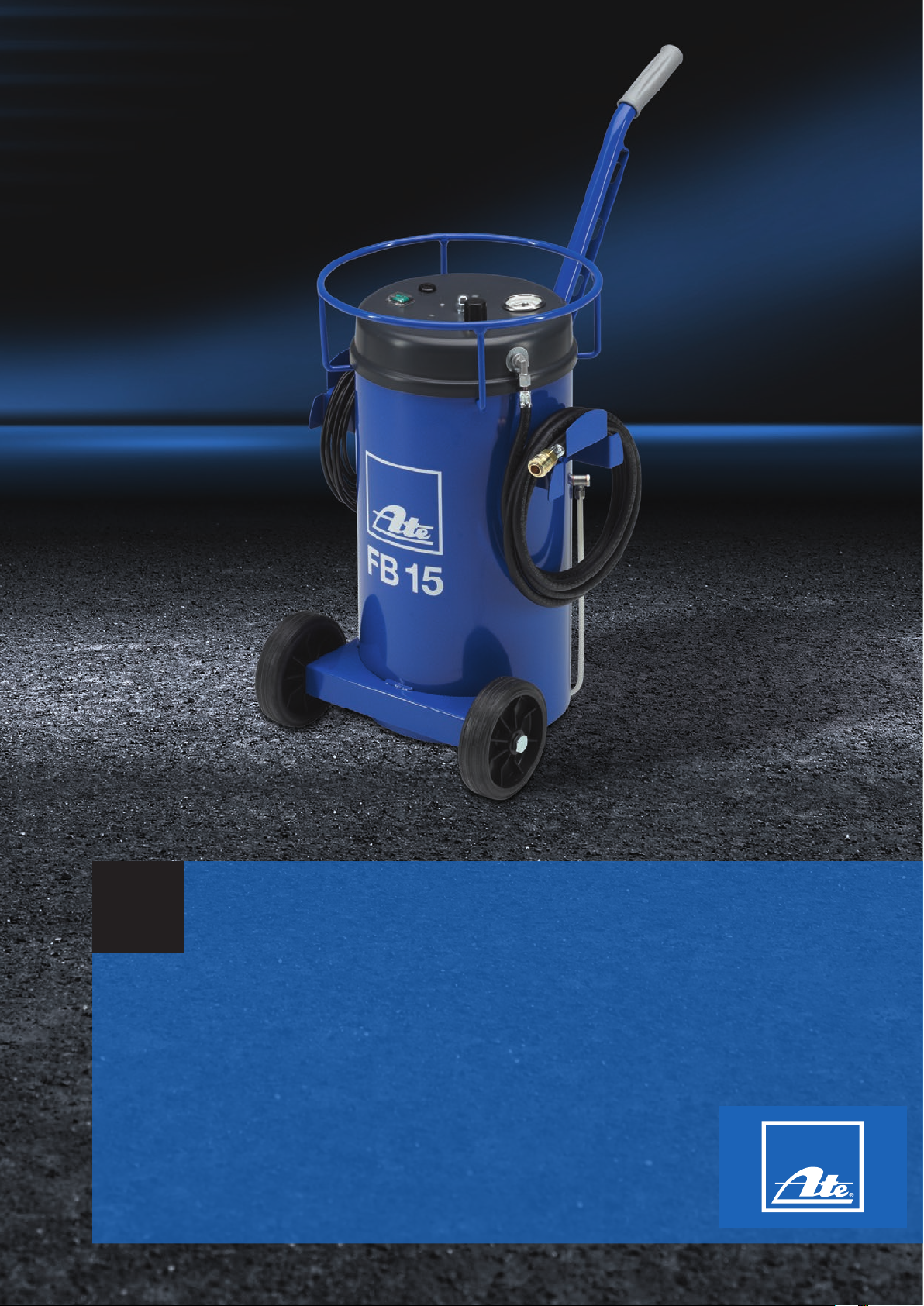
ATE FB 15
Page 2
2
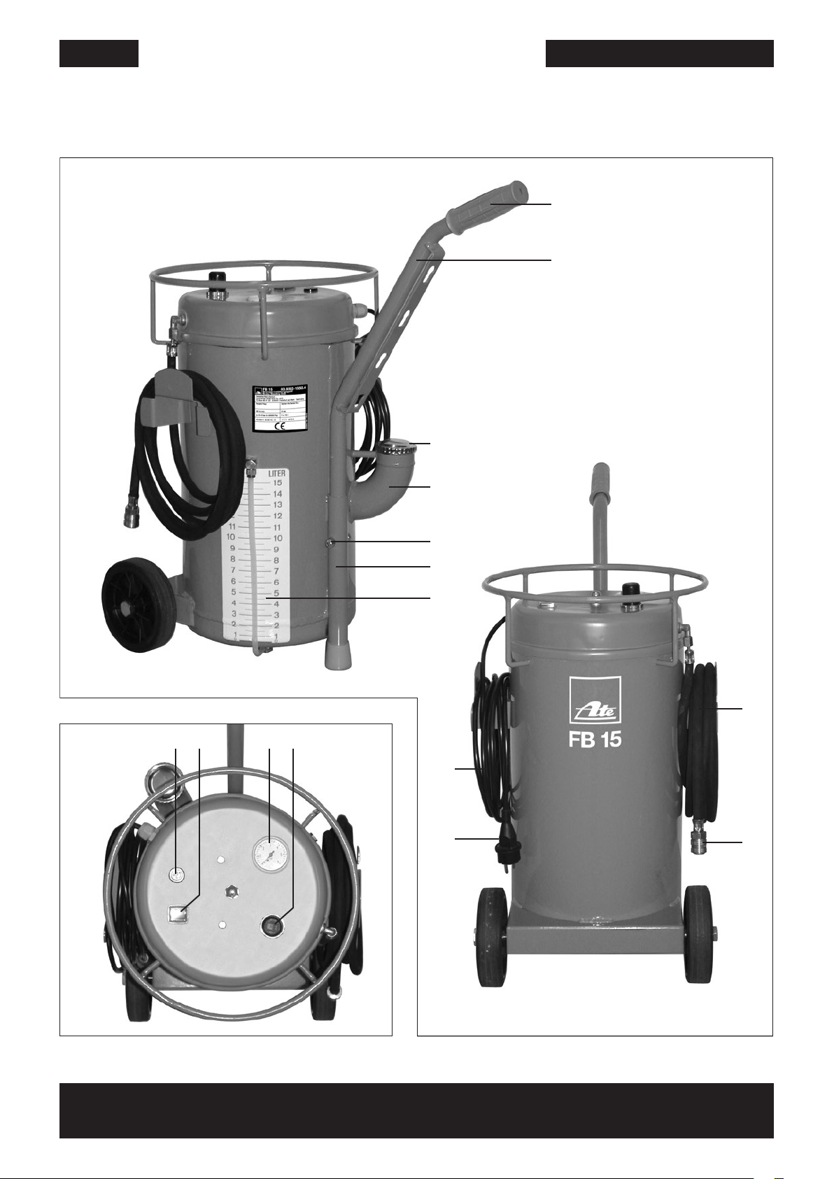
01 02 03 04
07
08
06
05
09
10
14
15
12
11
16
ATE FB 15
© Continental Aftermarket GmbH
Page 3
ATE FB15 Betriebsanleitung
DE
3
Vorwort
Lesen Sie bitte diese Betriebsanleitung
sorgfältig durch. Beachten Sie vor allem
die Sicherheitshinweise auf den ersten
Seiten dieser Betriebsanleitung! Bewahren Sie bitte die Betriebsanleitung zum
späteren Nachschlagen auf. Geben Sie
diese an eventuelle Nachbesitzer des
Gerätes weiter.
Arbeiten an Bremsanlagen dürfen nur
von geschultem Fachpersonal mit entsprechender Werkstattausrüstung durchgeführt werden.
Anwendung/Eigenschaften
• Schnelles, praktisches Füllen, Entlüften, Wechseln von Bremsflüssigkeit
an hydraulischen Bremsanlagen/
Kupplungsbetätigungen
• Durch den großen Bremsflüssigkeitsvorrat von 15 Litern sind entsprechend
viele BremsflüssigkeitswechselVorgänge ohne Nachfüllen möglich
• Arbeiten nach der "Ein-MannMethode"
• Einfachste Anwendung durch übersichtlichen Aufbau
• Ergonomisch angeordnete Bedienelemente
• Mobil durch Laufrollen und Rangiergriff
• Praxisgerechte Länge von Füllschlauch
und Kabelanschluss
• Einstellbarer, konstanter Arbeitsdruck
durch E-Motor/Pumpe/Druckregler
• ABS erprobt und einsetzbar
Sicherheitshinweise
zum Gerät
Das Gerät darf nur an ein Stromnetz angeschlossen werden, dessen Spannung,
Stromart und Frequenz mit den Angaben
auf dem Typschild übereinstimmen!
Den Netzstecker (05) nie an der Zuleitung
aus der Steckdose ziehen!
Das Gerät nicht in Betrieb nehmen,
wenn:
• die Zuleitung (06) beschädigt ist,
• das Gehäuse oder der Füllschlauch
(07/08) sichtbare Beschädigungen aufweist.
Nur mit reiner Bremsflüssigkeit
auf glykolischer Basis (DOT 3,
DOT 4, DOT 5.1) betreiben.
Mineralölhaltige Produkte führen
zur Zerstörung des Gerätes.
Vor Wartung oder Reinigung darauf
achten, daß das Gerät ausgeschaltet
und der Netzstecker (05) gezogen ist!
Bei einer eventuell erforderlichen Reparatur einschließlich Ersatz der Netzzu leitung ist das Gerät an den Fachhändler
(da der Einsatz von Spezialwerkzeug erforderlich ist) einzusenden, bei dem das
Gerät erworben wurde. Reparaturen an
Elektrogeräten dürfen nur von Fachkräften durchgeführt werden. Durch un sachgemäße Reparaturen können erheb liche
Gefahren für den Benutzer entstehen.
Wird das Gerät zweckentfremdet oder
falsch bedient, kann keine Haftung für
eventuelle Schäden übernommen werden.
Dieses Gerät ist nach CE geprüft.
Sicherheitshinweis
zur Bremsflüssigkeit
• Bremsflüssigkeit stets verschlossen
nur in Original-Gebinden so lagern,
dass sie für Kinder und andere Personen, die die Aufschrift nicht lesen
können, nicht zugänglich sind.
• Trinken von Bremsflüssigkeit kann
zu Vergiftungserscheinungen wie Kopfschmerzen, Schwindel, Magenschmerzen, Erbrechen, Durchfall, sogar zu
Krämpfen und Bewusst losigkeit führen.
Größere Mengen können
tödliche Folgen haben.
• Ist Bremsflüssigkeit in die Augen oder
auf empfindliche Körperteile gelangt,
sofort die Augen oder diese Körperteile mit viel sauberem Wasser spülen.
Liegt eine Augenreizung vor, sollte
man den Augenarzt aufsuchen.
• Zur Vermeidung von Hautschäden
Bremsflüssigkeit nur so kurz wie
möglich auf die Haut einwirken lassen
• Benetzte Kleidung schnellstmöglich
wechseln
• Sollte Flüssigkeit mit Lack in Berührung
kommen, sofort mit reichlich Wasser
abwaschen.
Hinweise zum Gerät
Geräte-Montage
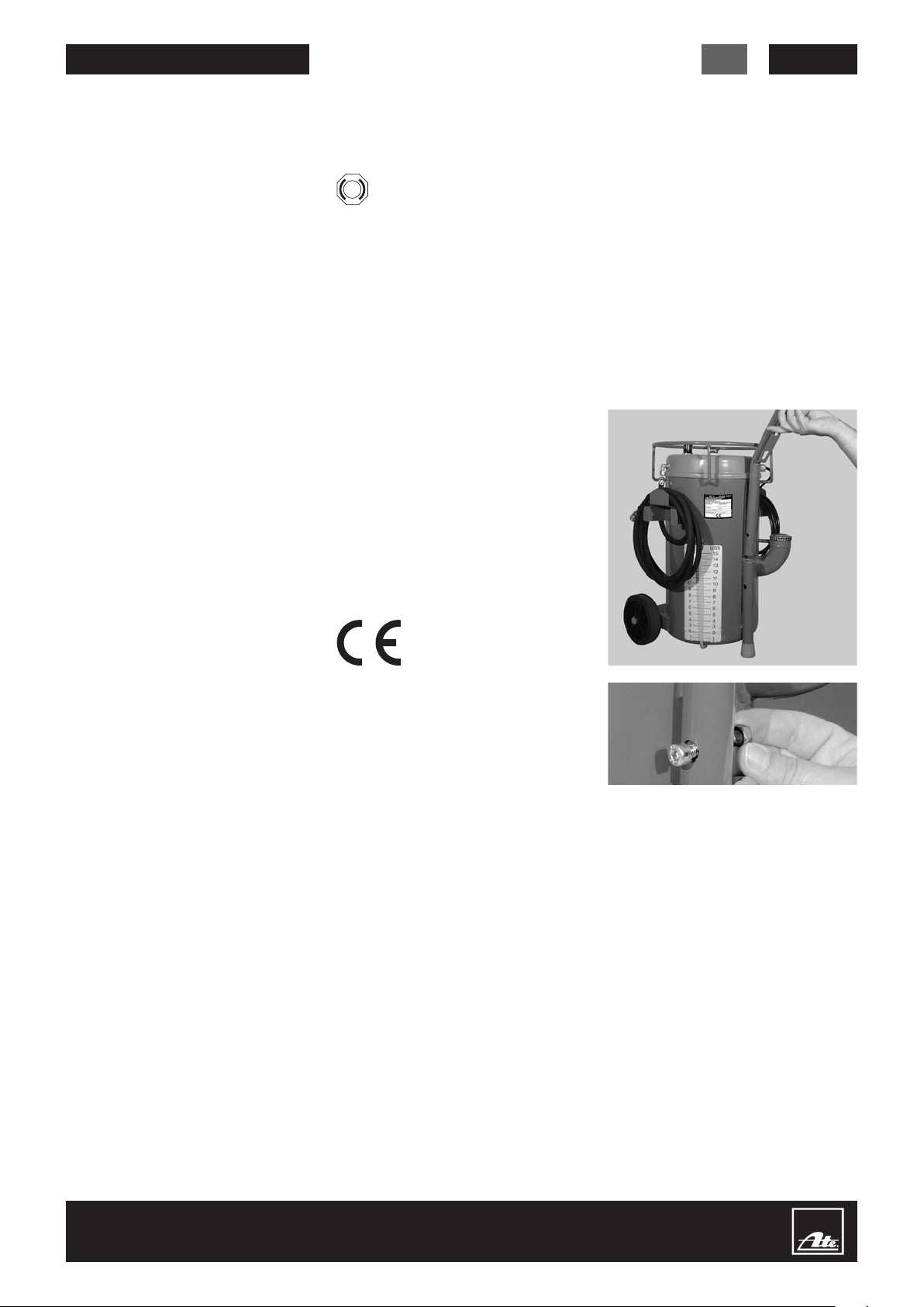
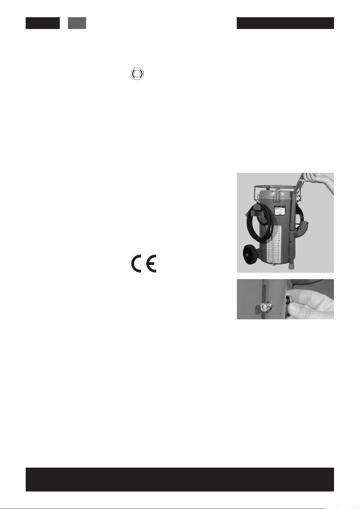
Den Rangiergriff (10) in das Halterohr (11)
schieben. Die Innensechskantschraube
M8 (12) einsetzen und mit der Mutter (13)
verschrauben.
Elektro-Sicherung austauschen
Gerät zeigt nach einschalten keine
Funktion, eine Überprüfung lässt keinen
offensichtlichen Defekt erkennen:
Sicherung austauschen
• Vor Sicherungswechsel elektrische Zuleitung vom Netzanschluss trennen!
• Schraubkopf (02) mit Schraubendreher
herausschrauben
• Elektro-Sicherung entnehmen
• Neue Sicherung (230 V 2 A MT 5x20)
einsetzen
• Schraubkopf (02) einschrauben
• Gerät an Netz anschließen und einschalten.
Geräte-Instandsetzung
Instandsetzungsarbeiten dürfen nur bei
autorisierten Kundendiensten erfolgen!
Page 4
4
DE
ATE FB 15 Betriebsanleitung
Inbetriebnahme
1. Bremsflüssigkeitseinfüllverschluss (14)
abnehmen, Bremsflüssigkeit einfüllen –
maximale Füllmenge 15 Liter –; Einfüllrohr (15) wieder verschließen
2. Die Füllmenge wird an der Flüssigkeitsanzeige (16) angezeigt
3. Netzstecker (05) an ordnungsgemäße
Schutzkontaktsteckdose anschließen
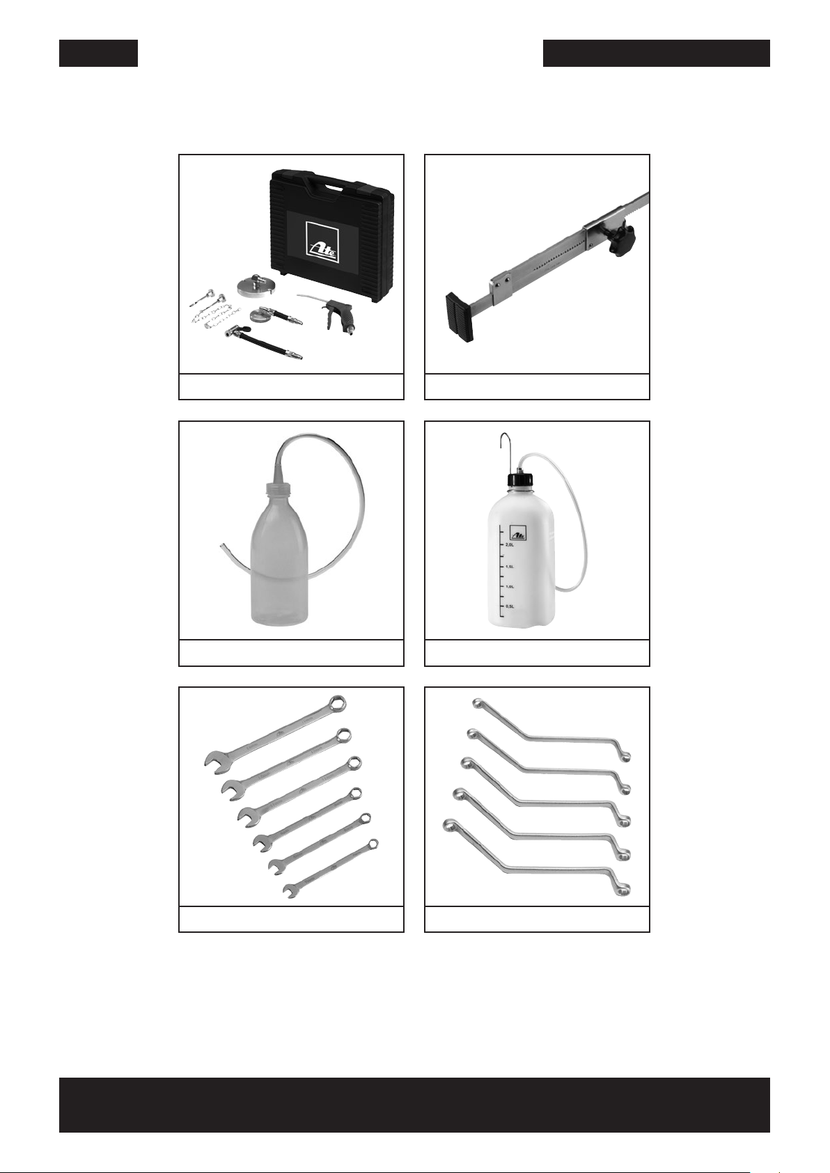
4. Zum Entlüften des Gerätes ATE-Füllpistole (B) oder ATE-Entlüfterstutzen
(C) an den Füllschlauch (07/08) ankuppeln; die austretende Flüssigkeit kann
durch das Einfüllrohr (15) am Gerät
zurückgeführt werden
5. Das Gerät am Ein- / Ausschalter (01)
einschalten, 10 sec. laufen lassen,
Gerät ausschalten
6. ATE-Füllpistole (B) bzw. ATE-Entlüfterstutzen (C) abkoppeln
7. Gerät ist betriebsbereit
Arbeitsdruck einstellen
Der Arbeitsdruck sollte vor
jeder Benutzung des Gerätes
überprüft werden.
Zum Überprüfen des eingestellten Arbeitsdrucks die ATE-Füllpistole (B) bzw.
den ATE-Entlüfterstutzen (C) entfernen.
Arbeitsdruck am Arbeitsmanometer (03)
bei eingeschaltetem Gerät ablesen.
Arbeitsdruck ist bei Auslieferung auf
2 bar (200000 Pa) eingestellt. Dies ist
normaler Entlüftungsdruck für hydraulische Bremsanlagen.
Verändern des Arbeitsdrucks nur bei
ausgeschaltetem Gerät.
Entlüften mit niedrigerem oder höherem
Arbeitsdruck: Druckreglerknopf (04)
durch Ziehen entriegeln.
Hineindrehen (
= Arbeitsdruck erhöhen
Herausdrehen (
= Arbeitsdruck reduzieren
Gerät einschalten und Arbeitsdruck
überprüfen. Gegebenenfalls Gerät erneut ausschalten und nachkorrigieren.
Nach korrekt eingestelltem Arbeits druck
Druckreglerknopf (04) wieder zum
Sichern hineindrücken.
⟳
⟲
)
)
Bremsflüssigkeit nachfüllen
Bei einer Bremsflüssigkeitsrestmenge
von ca. 0,5 Liter im Gerät wird der Motor
mit Pumpe automatisch ausgeschaltet,
damit keine Luft in das Bremssystem gepumpt wird. Gleichzeitig setzt Summton
ein, der Abschaltung und leeres Gerät
signalisiert.
• Gerät ausschalten
• Bremsflüssigkeitseinfüllverschluss (14)
abnehmen
• Neue Bremsflüssigkeit nachfüllen
• Einfüllrohr (15) wieder verschließen
• Gerät ist ohne Entlüften wieder
betriebsbereit
Hinweise zum Entlüften
Bei ABS Fahrzeugen unbedingt
die speziellen Fahrzeugher-
steller Entlüftungs-Richtlinien
einhalten.
Bei ABS Fahrzeugen immer
einige Regelbremsungen auf
abgesperrter Strecke durchführen und falls nötig die Entlüftungsvorgänge wiederholen
• Vor dem Entlüften Bremskreisaufteilung prüfen; jeden Kreis vollständig
entlüften
• Unbedingt an allen vorhandenen
Entlüfterventilen entlüften. Einzelne
Bremsaggregate können mehrere
Entlüfterventile haben
• Entlüfterventile nach dem Entlüften
vorschriftsmäßig (Drehmoment) festziehen; Gummistaubkappe aufstecken
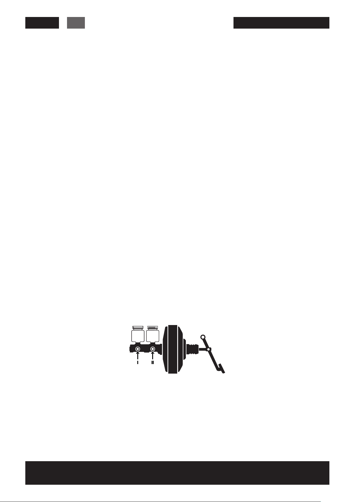
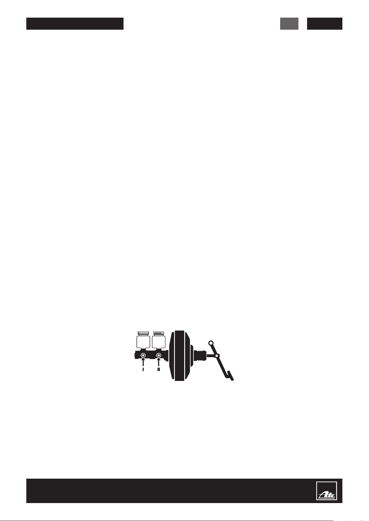
• Bei Zweikreisbremsanlagen mit getrennten Ausgleichsbehältern an beiden Bremskreisen nacheinander entlüften; zuerst Zwischenkolben-(I) danach Druckstangenkolben-Kreis (II)
• Bei Bremsanlagen mit lastabhängigem
Bremskraftregler kann bei entlasteten
Achsen (Fahrzeug auf 2-Säulen-Hebebühne) der hydraulische Durchgang zu
den geregelten Bremsen gesperrt sein.
In diesem Fall Räder der geregelten
Achsen belasten oder Regler auf Volllaststellung betätigen.
• Ist nach der Entlüftung der Betätigungsweg am Bremspedal zu lang
oder der Druckaufbau zu „weich“;
nach mehrmaliger kräftiger Betätigung
des Bremspedals erneut entlüften.
• Nach jeder Füllung, Entlüftung, Bremsflüssigkeitswechsel eine Dichtheits-,
Funktions- und Wirkungsprüfung der
Betriebsbremsanlage durchführen!
Bremsanlage Füllen,
Entlüften, Bremsflüssigkeit
wechseln
1. Ausgleichbehälter-Verschluss
abnehmen
2. Mit ATE-Absaugflasche (A) Brems-
flüssigkeit vollständig aus Ausgleichbehälter absaugen
3. ATE-Füllpistole (B) an Füllschlauch
(07/08) ankuppeln; Gerät einschalten
4. Ausgleichbehälter mit neuer Brems-
flüssigkeit randvoll füllen; ATE-Füllpistole (B) abkuppeln
5. Passenden ATE-Entlüfterstutzen (C)
auf Ausgleichsbehälter druckdicht
montieren
6. Füllschlauch (07/08) an ATE-Entlüfter-
stutzen (C) ankuppeln
7. Auf ein Entlüfterventil Schlauch der
ATE-Auffangflasche (D) stecken; Entlüfterventil solange öffnen bis neue,
klare, blasenfreie Bremsflüssigkeit
ausströmt
8. Nacheinander an jedem Entlüfter ventil
mit angeschlossener Auffangflasche
Vorgang wiederholen
9. Beim Einbau eines neuen Tandem-
Hauptzylinders:
Während Bremsflüssigkeit ausströmt
das Bremspedal einige Male langsam
bis zum Anschlag betätigen, um im
Tandem-Hauptzylinder die Luftblasen
vollständig zu entfernen
10. Ende der Entlüftung, Gerät ausschal-
ten; zuerst Füllschlauch (07/08) dann
ATE-Entlüfterstutzen (C) abnehmen
11. Bremsflüssigkeit mit ATE-Absaug-
flasche (A) auf MAX-Markierung korrigieren
12. Entlüftungsbohrung des Original-
Ausgleichbehälter-Verschluss auf
Durchlässigkeit prüfen und diesen
anschließend montieren
© Continental Aftermarket GmbH
Page 5
ATE FB15 Betriebsanleitung
DE
5
Sonderentlüftung
Sonderentlüftungen sind für
Fahrzeuge mit ABS nicht zulässig
1. Entlüften in Sonderfällen über Entlüfterventil (von unten nach oben). Nur
mit dieser Methode darf mit mehr als
2 bar (200000 Pa) entlüftet werden.
2. Mit ATE-Absaugflasche (A) Bremsflüssigkeit aus Ausgleichsbehälter
vollständig absaugen
3. ATE-Füllpistole (B) an Füllschlauch
(07/08) kuppeln; Gerät einschalten
4. Ausgleichsbehälter bis MAX-Markierung füllen; ATE-Füllpistole (B) abkuppeln
5. ATE-Auffangflasche (D) an ein Entlüfterventil anschließen, dieses Entlüfterventil öffnen
6. Bremspedal bis Anschlag betätigen
und mit ATE-Pedalfeststeller (E) feststellen
7. Hebelnippel vom ATE-Zusatzschlauch
(F) an ein weiteres Entlüfterventil des
gleichen Bremskreises anschließen,
dieses Entlüfterventil öffnen
8. Füllschlauch (07/08) an ATE-Zusatzschlauch (F) kuppeln
9. Jedes Entlüfterventil des Bremskreises bei angeschlossener ATE-Auffangflasche (D) solange öffnen bis
neue, klare, blasenfreie Bremsflüssigkeit ausströmt
10. Ende der Entlüftung, Entlüfterventil
am ATE-Zusatzschlauch (F) schließen; Gerät ausschalten; zuerst
Füllschlauch (07/08) dann ATE-Zusatzschlauch (F) abnehmen; zweiten
Bremskreis entsprechend entlüften
11. ATE-Pedalfeststeller (E) entfernen
12. Bremsflüssigkeit im Ausgleichsbehälter bis MAX-Markierung korrigieren
NiederdruckDichtheitsprüfung
Soll eine Niederdruck-Dichtheitsprüfung
erfolgen bleibt das Gerät nach dem
normalen Entlüftungsvorgang am Ausgleichsbehälter angeschlossen.
• Bei eingeschaltetem Gerät Druckreg-
lerknopf (04) durch Ziehen entriegeln,
Knopf (
herausdrehen
• Gerät ausschalten, Anlage 5 Minuten
stehen lassen
) ganz bis zum Anschlag
⟲
• In dieser Zeit darf Druck nicht abfallen
• Bei Druckabfall Bremsanlage überprüfen
Danach Gerät wieder auf 2 bar
(200000 Pa) einstellen.
Kupplungsanlage
Füllen und Entlüften
Die Entlüftung der hydraulischen Kupplungsanlage wird über den Ausgleichbehälter des Geberzylinders durchgeführt.
Bei eventuell auftretenden Entlüftungsschwierigkeiten (LKW und Omnibus)
kann, unter Verwendung von und ATEZusatzschlauch (F), auch vom Entlüfterventil des Nehmerzylinders aus entlüftet
werden.
Entsorgung von
Bremsflüssigkeit
Bremsflüssigkeit ist sortenrein in einem
geeigneten Sammelbehälter (ATE-220 Liter Sammelbehältersystem (G)) zu sammeln und durch einen zugelassenen Entsorger zu entsorgen.
Bremsflüssigkeit darf nicht mit
anderen Flüssigkeiten vermischt
werden, da sie sonst als teurer
Sondermüll entsorgt werden
muss.
Zusatzinformation:
Gebrauchte Bremsflüssigkeit unterliegt
dem `Kreislaufwirtschafts- und Abfallgesetz (KrW-/AbfG)´und ist in `Wassergefährdungsklasse 1´eingestuft.
Unter Beachtung der gesetzlichen und
behördlichen Vorschriften ist die Bremsflüssigkeit (ohne Fremdstoffe) einer
hier für zugelassenen Recycling-, Verwertungsanlage (auch energetische Nutzung)
oder einer Sonderabfall-Verbrennungsanlage zuzuführen.
Das bedeutet, abgelassene Bremsflüssigkeit:
• gehört zu den wasser gefährdenden
Flüssigkeiten
• darf nicht in Abflüsse, Kanäle oder
dergleichen gegeben werden
• darf nicht mit dem Hausmüll entsorgt
werden
• fällt nicht unter die Bestimmungen des
Altölgesetzes
• darf nicht dem Altöl zugesetzt werden
Zur Vermeidung von Vermischungen
muss Bremsflüssigkeit separat gesammelt, über einen zugelassenen AbfallEntsorger (Transporteur) einer zugelassenen Recycling-, Verwertungsanlage
oder Sonderabfall-Verbrennungsanlage
zugeführt werden.
Bremsflüssigkeit hat den LAGA-Code
553 36
Technische Daten
Höhe 745 mm
Breite 380 mm
Tiefe 705 mm
Leergewicht 20,5 kg
Inhalt 15 l
Netzanschluss 230 V 50–60 Hz
Leistung E-Motor 125 W
Fördermenge der Pumpe 1,3 l/min
Druckregler eingestellt auf 2 bar (200000 Pa)
einstellbar 0–3 bar (0–300000 Pa)
Endabschaltung der Pumpe automatisch bei ca. 0,5 l Restmenge mit Summton
Elektro-Sicherung 230 V 2 A MT 5 x 20 mm
Arbeitsmanometer 0– 6 bar (0–600000 Pa)
Elektrokabel-Länge 4,20 m
Füllschlauch-Länge 3,50 m
Technisch bedingte Änderungen, auch Kontruktions-Änderungen bleiben ausdrücklich vorbehalten.
Page 6
6
GB
ATE FB15 Operating Manual
ATE Brake Bleeding Unit FB 15
Preface
Please read through this operating
manual carefully. Pay particular attention
to the safety instructions on the first
pages of this operating manual! Always
keep the operating manual for future
reference. Pass on the manual to any
subsequent owners of the unit.
Work on brake units may only be
carried out by trained specialists using
appropriate workshop equipment.
Application/characteristics
• Fast, practical filling, bleeding,
replacement of brake fluids in
hydraulic brake/clutch systems
• Thanks to the brake fluid tank capacity
of 15 liters, a large number of brake
fluid replacement procedures can
be carried out without refilling being
necessary
• Can be operated by one person
• Extremely straightforward to use
thanks to clear design
• Ergonomically positioned control
elements
• Mobile thanks to casters and steering
handle
• Length of filling hose and power cable
connection appropriate for practical
requirements
• Adjustable constant working pressure
through E-motor/pump/pressure
regulator
• ABS-tested and usable
Safety instructions
for the unit
The voltage, type of current and
frequency of the power supply used
must correspond to the specifications
on the type plate.
Never pull the mains connector (05) by
the power cable to remove it from the
socket.
Do not operate the unit if:
• the power cable (06) is damaged,
• the housing or filling hose (07/08) show
visible signs of damage.
Only operate with pure glycol-
based brake fluid (DOT 3, DOT 4,
DOT 5 .1).
Products containing mineral oils
will lead to destruction of the
unit.
Before maintenance or cleaning, make
sure that the unit is switched off and the
mains connector (05) has been disconnected from the power supply.
If any repairs should become necessary,
including replacement of the mains supply power cable, the unit must be sent to
the specialist retailer it was purchased
from, since specialist tools are required.
Repairs to electric devices may only be
carried out by specialists. Incorrectly
performed repairs can lead to significant
hazards for the user.
If the unit is used for purposes other
than those intended or operated incorrectly, no liability can be accepted for
any damage caused.
This unit has been tested in accordance
with CE.
Safety note on brake fluid
• Always store brake fluid sealed in the
original containers in such a way that
they are not accessible to children and
other people who cannot read the label.
• Drinking brake fluid can lead to symptoms of poisoning such as headache,
dizziness, stomach pain, vomiting, and
diarrhea or even to cramps and loss of
consciousness.
Larger quantities can be fatal.
• If brake fluid gets into the eyes or onto
sensitive body parts, rinse the eyes
or these body parts immediately with
plenty of clean water. If the eyes are
irritated, visit an eye specialist.
• To avoid damage to the skin, minimize
the contact time of brake fluid with the
skin as much as possible
• Wet clothing should be changed as
quickly as possible
• If the fluid should come into contact
with paint, rinse off immediately using
plenty of water.
Unit instructions
Unit assembly
Push the steering handling (10) into the
stay tube (11). Insert the hexagon socket
screw M8 (12) and screw in place with
the nut (13).
Replace the electric fuse
Unit does not work when switched on;
checks do not reveal any obvious defect:
Replace the fuse.
• Before replacing the fuse, disconnect
the cable from the mains socket.
• Use a screwdriver to unscrew the
screw head (02)
• Remove the electric fuse
• Fit new fuse (230 V 2 A MT 5x20)
• Screw the screw head (02) in again
• Connect the unit to the mains and
switch on.
Unit repairs
Repair work may only be carried out by
authorized customer services.
© Continental Aftermarket GmbH
Page 7
ATE FB15 Operating Manual
GB
7
Commissioning
1. Remove the fluid filling cap (14), fill
with fluid – maximum filling capacity
15 liters–; seal the filling tube (15) again
2. The filling level is shown on the fluidlevel indicator
3. Connect the mains connector (05) to
a correctly earthed socket
4. To bleed the unit, connect ATE filling
gun (B) or ATE bleeding unit adapter
(C) to the filling hose (07/08); the
extracted fluid can be returned to the
unit via the filling tube (15).
5. Switch the unit on using the on/off
switch (01), allow it to run for 10 sec.,
and then switch the unit off
6. Disconnect ATE filling gun (B) or ATE
bleeding unit adapter (C)
7. The unit is ready for operation
Setting working pressure
The working pressure should be
checked every time the unit is
used.
To check the working pressure set,
remove the ATE filling gun (B) or the
ATE bleeding unit adapter (C).
With the unit switched on, read off the
working pressure at the working-pressure
manometer (03).
On delivery, the unit is set to a working
pressure of 2 bar (200,000 Pa). This
is the standard bleeding pressure for
hydraulic brake systems.
Only change the working pressure setting when the unit is switched off.
Bleeding with lower or higher working
pressure: Pull the pressure regulator
button (04) to release it.
Screw in (
increase working pressure
Screw out (
reduce working pressure
Switch the unit on and check the working pressure. If necessary, switch the
unit on again and re-adjust the pressure.
After correct setting of the working pressure, press the pressure regulator button
(04) back in to secure it.
⟳
⟲
) =
) =
Refilling brake fluid
If there is less than approx. 0.5 liters of
brake fluid in the unit, the pump motor
automatically switches off to prevent air
being pumped into the brake system.
At the same time, a buzzing noise is
sounded which signalizes switch-off and
an empty unit.
• Switch the unit off
• Remove the brake fluid filling cap (14)
• Replenish with new brake fluid
• Seal the filling tube (15) again
• The unit does not require bleeding
before operation
Bleeding instructions
With ABS vehicles always follow
the special bleeding guidelines
provided by the vehicle manufacturer.
With ABS vehicles, always carry
out controlled braking several
times on a blocked road and
repeat the bleeding procedure
if necessary.
• Before bleeding, check the brake circuit
layout; bleed each circuit completely
• Always carry out bleeding at all the
bleed valves available. Some braking
units can have several bleed valves.
• After bleeding, tighten the bleed valves
according to requirements (torque);
replace rubber dust cap
• In the case of dual-circuit brakes with
separate fluid reservoirs on each of the
brake circuits, bleed the two circuits in
succession; first the intermediate piston
(I) then the primary piston circuit (II)
• In the case of brake systems with loaddependent brake power regulators,
the hydraulic passage to the regulated
brakes can be blocked on unburdened
axles (vehicle on 2-pillar lifting platform).
In this case, burden the wheels of the
regulated axles or actuate the regulator
in full-load position.
• If brake pedal travel is too long or
pressure build-up too “soft” after
bleeding has been carried out, bleed
again after pressing the brake pedal
forcefully several times.
• After every filling, bleeding, and brake
fluid replacement process, carry out
leakage, function and efficiency tests
on the service brake system.
Filling, bleeding the brake
system, replacing brake fluid
1. Remove the fluid reservoir cap
2. Extract the brake fluid completely
from the fluid reservoir using the ATE
suction bottle (A)
3. Connect the ATE filling gun (B) to the
filling hose (07/08); switch the unit on
4. Completely fill the brake fluid reser-
voir with new fluid; disconnect the
ATE filling gun (B)
5. Fit the suitable ATE bleeding unit ad-
apter (C) airtight to the fluid reservoir
6. Connect the filling hose (07/08) to the
ATE bleeding unit adapter (C)
7. Insert the hose of the ATE collection
bottle (D) onto a bleed valve; open
the bleed valve until fresh, clear,
bubble-free brake fluid flows out
8. Repeat the procedure on each of the
bleed valves with the collection bottle
fitted
9. When fitting a new tandem main
cylinder: Press the brake pedal down
as far as it will go several times while
the brake fluid is flowing out in order
to remove the air bubbles completely
from the tandem main cylinder
10. End of bleeding; switch the unit
off; remove the filling hose (07/08)
first, then the ATE bleeding unit
adapter (C)
11. Correct the brake fluid to the MAX
mark using the ATE suction bottle (A)
12. Check the bleeding hole of
the original fluid reservoir cap
for permeability and then fit it
Page 8

8
GB
ATE FB15 Operating Manual
Special bleeding
Special bleeding is not permitted
on vehicles with ABS
1. Bleeding in special cases via bleed
valve (from bottom to top). This
method must be used when bleeding
at more than 2 bar (200,000 Pa).
2. Extract the brake fluid completely
from the fluid reservoir using ATE
suction bottle (A)
3. Connect the ATE filling gun (B) to the
filling hose (07/08); switch the unit on
4. Fill the fluid reservoir up to the MAX
mark; disconnect the ATE filling gun (B)
5. Connect the ATE collecting bottle (D)
to a bleed valve; open this bleed valve
6. Press the brake pedal down as far
as it will go and fix in place using the
ATE pedal arrester (E)
7. Connect the lever nipple of the
auxiliary hose (F) to a further bleed
valve of the same brake circuit; open
this bleed valve
8. Connect the filling hose (07/08) to the
ATE auxiliary hose (F)
9. Open every bleed valve in the brake
circuit with the ATE collection bottle
(D) connected until fresh, clear,
bubble-free brake fluid flows out
10. End of bleeding; close bleed valve on
the ATE auxiliary hose (F); switch the
unit off; remove the filling hose (07/08)
first, then the ATE auxiliary hose (F);
bleed the second brake circuit
accordingly
11. Remove the ATE pedal arrester (E)
12. Correct the brake fluid in the fluid
reservoir up to the MAX marking
Low-pressure leakage test
If a low-pressure leakage test is to be
carried out, the unit remains connected
to the fluid reservoir after the standard
bleeding procedure.
• With the unit switched on, pull the
pressure regulator button (04) to
release it, and screw out (
far as possible
⟲
) as
• Switch the unit off; allow the system to
stand for 5 minutes
• The pressure must not decrease
during this period
• If the pressure does decrease, check
the brake system
Afterward, set the unit to 2 bar
(200,000 Pa) again.
Filling and bleeding the
clutch system
The hydraulic clutch system is bled via
the master cylinder reservoir. If any problems with bleeding occur (on trucks and
buses), bleeding can take place via the
bleed valve of the slave cylinder using
the ATE auxiliary hose (F).
Disposing of brake fluid
Brake fluid must be collected separately
in a suitable container (ATE 220 liter
collecting tank system (G)) and disposed
of by an approved disposal company.
Brake fluid must not be mixed
with other fluids, since it must
otherwise be disposed of as
expensive special waste.
Additional information:
Used brake fluid is subject to the
'Recycling Management and Waste
Law (KrW-/AbfG)' in Germany, and is
classified as 'Water Hazard Class 1'.
Taking the legal and official regulations
into account, brake fluid (without external
substances) must be sent to an approved
recycling plant (including energy use) or
to a special waste combustion plant.
This means that drained brake fluid:
• is a fluid that presents a contamination
hazard to water
• must not be discharged into drains,
sewage channels or similar
• must not be disposed of with household waste
• is not subject to the requirements of
the Used Oil Law
• must not be added to used oil
To avoid mixing, brake fluid must be
collected separately and sent to an approved recycling plant or special waste
combustion plant via an approved waste
disposal company (transport company).
Brake fluid has the LAGA code 553 36
Technical data
Height 745 mm
Width 380 mm
Depth 705 mm
Empty weight 20.5 kg
Contents 15 l
Power supply 230 V 50–60 Hz
E-motor capacity 125 W
Delivery rate of pump 1.3 l/min
Pressure regulator set to 2 bar (200,000 Pa)
adjustable 0–3 bar (0–300,000 Pa)
Final switch-off of the pump automatically with 0.5 l residual fluid, with buzzing noise
Electric fuse 230 V 2 A MT 5 x 20 mm
Working pressure manometer 0–6 bar (0–600,000 Pa)
Electric cable length 4.20 m
Filling hose length 3.50 m
© Continental Aftermarket GmbH
We expressly reserve the right to make technical modifications, including modifications to the design.
Page 9
03.9302-9211.3 / 740266
ATE FB 15
5x20 mm M 2A 250V
03.9302-9022.2 / 740244
03.9302-9250.1 / 740267
03.9302-9200.2 / 740264
03.9302-9070.3 / 740257
03.9302-9052.3 / 740254
03.9302-9003.3 / 740238
03.9302-9402.3 / 740269
03.9302-1660.4 / 740231
Page 10
10
ATE FB 15
03.9302-0800.3 / 740271
03.9312-0100.4 / 760032
03.9302-1424.2 / 74015103.9314-5910.3 / 760069
© Continental Aftermarket GmbH
03.9314-1500.3 / 760041 03.9314-1510.3 / 760103
Page 11
ATE FB 15
EC-Declaration of Conformity (CE)
Description of Product: Electrical Brake-Bleeding-Equipment
Type: ATE FB 15
The designated product is in conformity with the European Directive 2006/42/EG.
Full compliance with the standards listed below proves the conformity of the
designated product with the provisions of the above mentioned EC Directive:
DIN EN 61000-6-2 / 200603 + Ber. 1 2011.06 DIN EN 61000-4-5 / 2007.06
DIN EN 61000-4-2 / 2009.12 DIN EN 61000-4-6 / 2009.12
DIN EN 61000-4-3 / 2011.04 DIN EN 61000-4-11/2005.02
DIN EN 61000-4-4 / 2013.04 DIN EN 550011 / 2011.04
11
i
Altgerät darf nicht im Hausmüll entsorgt werden!
Altgerät zur Entsorgung bei dem Händler zurückgeben, bei dem
das Gerät erworben wurde. Das Gerät wird gemäß dem Elektround Elektronikgesetz (ElektroG) vom 16.03.05 entsorgt.
EAR Registrierungsnummer – Continental Aftermarket GmbH:
WEEE-Reg.Nr. DE 29322770
Page 12

ATE – Eine Marke des Continental-Konzerns
Continental Aftermarket GmbH
Guerickestrasse 7 · 60488 Frankfurt · Germany
Telefon +49 69 7603-1 · Fax +49 69 761061
91.9998- 4214.4/08.14 ©2014 Continental Aftermarket GmbH
www.ate.de
 Loading...