

Page 1

ATD-8699
MASTER BALL JOINT SET
WARNING: TO HELP PREVENT PERSONAL INJURY
z Always wear ANSI approved goggles when using this product. Normal use of this product is likely to expose the
user to dust and/or microscopic particles containing chemicals known to the State of California to cause cancer,
birth defects or other reproductive harm. Always wear appropriates safety equipment and clothing when using this
product.
z Study, understand, and follow all instructions provided with this product.
z Before repairing vehicle, block the wheels to prevent the vehicle from moving.
z Check the final alignment of the C-frame press and all tooling with components before exerting pressure to remove
or replace a ball joint.
OPERATING INSTRUCTIONS
Brake Anchor Pin Remo val and Installation
1. Remove all lock ring retainers from the brake anchor pins.
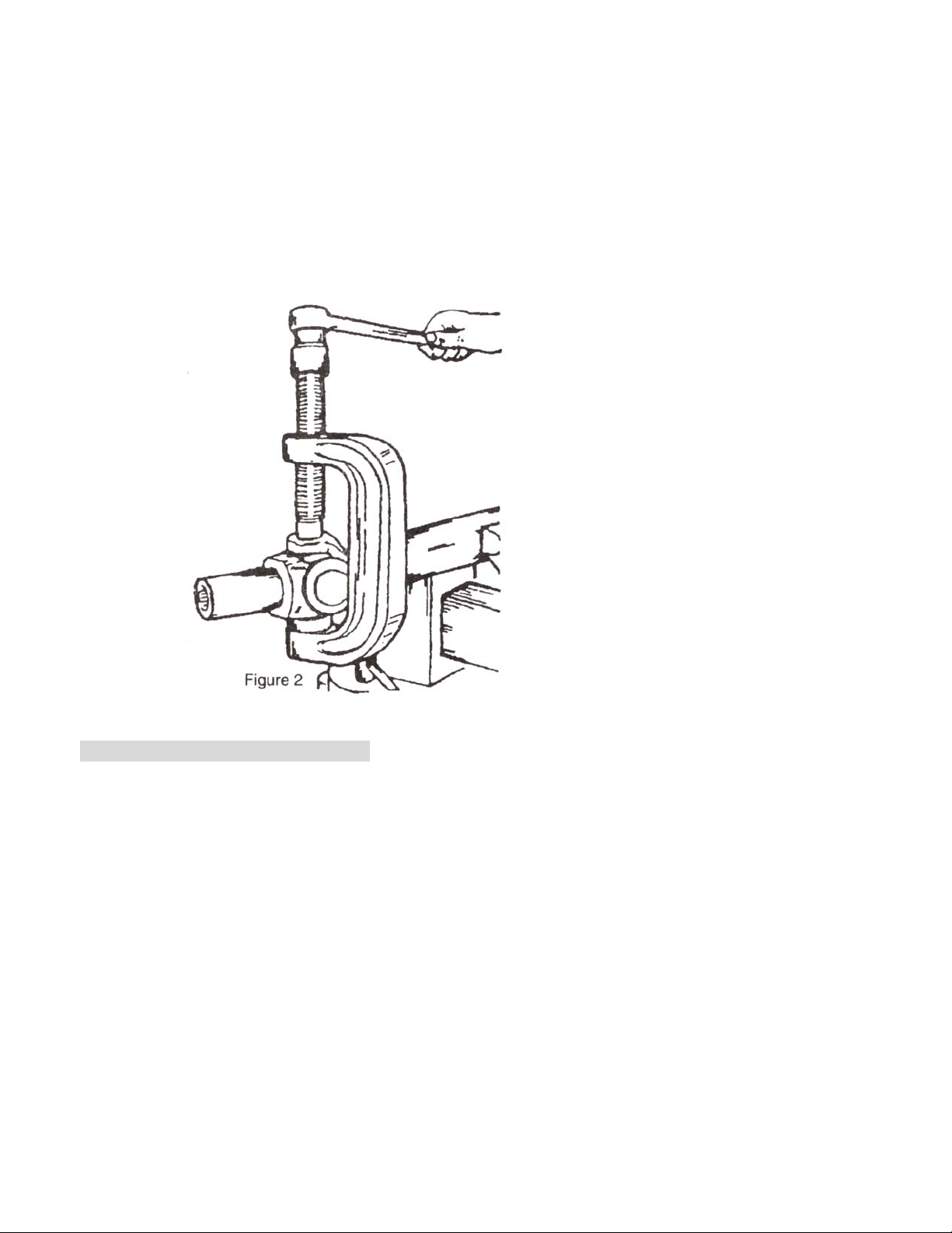
2. Position the C-frame press over the brake spider as shown in Figure 1.
3. Tighten the forci ng screw until the anchor pin is r emove d.
U-Joint Assembly and Disassembly
The basic C-frame press is used to service the U-Joints on most cars and light trucks.
The U-Joints can be serviced either on or off the v ehicle.
Disassembly
1. Remove any external and/or internal lock rings.
Page 2
2. Position the C-frame press around the drive shaft yoke, and tighten the forcing screw until the first bearing is
removed.
3. Reposition the C-frame and remove the second bearing.
Assembly
1. Clean all dirt and oil from the yoke area.
2. Align the replacement bearing and C-frame press as straight as possible over the yoke. Press the replacement
bearing into the yoke, and reassemble the external / internal lock ring.
3. Reposition the C-frame press and secon d repl acement b earing as str aight as possibl e over t he yoke, and pr ess the
bearing into the yoke. Reassemble the external / internal lock ring.
Ball Joint Re moval and Installation
This tool set is designed for use on all cars and li ght truck s that ha ve press-fit typ e ball join ts wi thout th e need to r emove
the control arm from the vehicle.
NOTE: Some cars and light trucks may have the upper ball joint spot-welded to the control arm. The weld must
be cut before attempting to remove the ball joint.
Removal
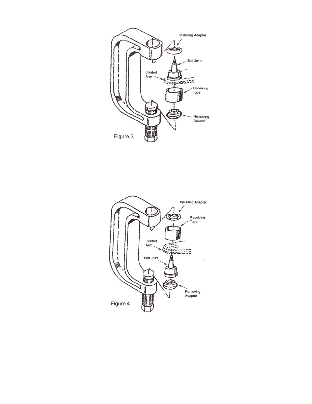
1. Assemble the ball joint pr es s over the control arm as shown in Figure 3. Select the correct size receiving tube (Item
6, 7, or 8), and position it under the vehicle ball joi nt refer to Figure 3.
2. Tighten the forcing screw until the receiving tube contacts the control arm. Check the alignment of all tooling and
components, and continue tightening the forcing screw until the ball joint is removed.
Page 3
Installation
1. Clean the control arm and coat the I.D. with a suitable lubricant.
2. Insert the replacement ball joint as straight as possible into the vehicle control arm.
3. Assemble the ball joint press component as shown in Figure 4. Position the receiving tube, and tighten the forcing
screw. Check the alignment of all tooling and components, and continue tightening the forcing screw until the ball
joint is firmly seated.
Page 4

ATD-8699
APPLICATION CHART
R=Remove I=Install
Ball
Joint
Upper/
Lower
Vehicle
DODGE / CHRYSLER / PLYMOUTH
1987-97 Dakota 2WD
Lower
Lower
Lower
Upper
Lower
Upper
Lower
Lower
Upper
Upper
Lower 1993-04 Grand Cherokee 4WD
Upper 1993-04 Grand Cherokee 4WD
Lower
Upper
1972-93 1/2-, 3/4-ton 2WD Pickup
1974-93 1/2-ton 2WD Ramcharger
1979-97 1/2-, 3/4-, 1-ton 2WD Van
1972-93 3/4-, 1-ton 2WD Pickup
1979-97 1-ton 2WD Van
1984-96 Caravan, Voyager,
Town & Country
1994-97 1/2-, 3/4-, 1-ton 2WD
Pickup(IFS)
1994-97 1/2-, 3/4-, 1-ton 2WD
Pickup(IFS)
1994-97 1-ton solid axle, 2WD;
3/4-, 1-ton Dana 60 axle, 4WD
1994-97 1-ton solid axle, 2WD;
3/4-, 1-ton Dana 60 axle, 4WD
1994-2006 1/2-, 3/4-ton Dana 44
axle,
4WD;
1972-93 1/2-, 3/4-, 1-ton 4WD &
Ramcharger
1994-2006 1/2-, 3/4-ton Dana 44
axle,
4WD
1972-93 1/2-, 3/4-, 1-ton 4WD &
Ramcharger
1994-01 Dodge Ram 4WD 1/2- Ton
Pickup
1994-01 Dodge Ram 4WD 1/2- Ton
Pickup
ATD-8699
PRT8697-13
PRT8697-14
PRT8697-03
PRT8697-06
PRT8697-12
PRT8697-07
PRT8697-10
PRT8697-09
PRT8697-11
PRT8697-02
PRT8697-04
PRT8697-08
PRT8697-05
PRT8697-01
PRT8696-03
PRT8696-06
PRT8696-10
I R RI
I R
R
I
I
I I
R I
I I
I R R I R I
I R R I R I
I R I
I R I R
I R I R
I R I R
I R I R
Page 5

R=Remove I=Install
Ball
Joint
Upper/
Lower
Vehicle
PRT8697-13
PRT8697-14
PRT8697-03
PRT8697-06
PRT8697-12
JEEP
1993-97 2WD Grand Cherokee
1993-95 4WD Grand Cherokee,
Upper
Lower
Upper
Lower
Upper
Lower
Grand Wagoneer
1987-98 4WD Wrangler
1984-95 4WD Wagoneer,
Comanche, Cherokee
1993-97 2WD Grand Cherokee,
1990-97 2WD Cherokee,
Wagoneer,
Comanche
1993-95 4WD Grand Cherokee,
Grand Wagoneer
1990-98 4WD Wrangler
1990-95 2WD & 4WD Wagoneer,
Comanche, Cherokee
1984-97 2WD Cherokee,
Wagoneer,
Comanche
1984-89 2WD Cherokee,
Wagoneer,
Comanche
1987-89 4WD Wrangler
1984-89 4WD Wagoneer,
Comanche,
Cherokee
1984-92 full size 4WD Grand
Wagoneer
1972-88 4WD Truck, CJ, full size
Cherokee, Wagoneer
1984-92 full size 4WD Grand
Wagoneer
1972-88 4WD Truck, CJ, full size
Cherokee, Wagoneer
I I R I R
I I R I R
I R I R
I I R I R
I R I
I R I
ATD-8699
PRT8697-07
PRT8697-10
PRT8697-09
PRT8697-11
PRT8697-02
PRT8697-04
PRT8697-08
PRT8697-05
PRT8697-01
PRT8696-03
PRT8696-06
PRT8696-10
Page 6

R=Remove I=Install
ATD-8699
Ball
Joint
Upper/
Lower
Vehicle
FORD
Lower 1986-97 Aero
1989-90 2WD Bronco Ⅱ
Upper
Upper
Lower
Lower
Lower 1997 1/2-ton Pickup, 2WD & 4WD R I
Upper
Lower 1987-96 1/2-ton 2WD Pickup
1991-94 2WD Explorer
1989-97 2WD Ranger
1987-88 2WD Bronco Ⅱ
1983-88 2WD Ranger
1989-90 2WD Bronco Ⅱ
1991-94 2WD Explorer
1989-97 2WD Ranger
1987-88 2WD Bronco Ⅱ
1983-88 2WD Ranger
1987-96 1/2-ton 2WD Pickup
1987-97 3/4-, 1-ton 2WD Pickup
1981-86 1/2-ton 2WD Pickup
PRT8697-13
PRT8697-14
PRT8697-03
PRT8697-06
PRT8697-12
PRT8697-07
PRT8697-10
PRT8697-09
PRT8697-11
PRT8697-02
PRT8697-04
PRT8697-08
PRT8697-05
PRT8697-01
PRT8696-03
PRT8696-06
PRT8696-10
I
I I
I
I
I R R I
I
I R R I
1980 4WD Bronco Ⅱ w/Dana 28
Upper
Lower
Lower 1987-97 3/4-, 1-ton 2WD R I
Upper 1992-97 1/2-,3/4-, 1-ton 2WD Van
Lower 1992-97 3/4-, 1-ton 2WD Van
Lower 1992-97 1/2-ton 2WD Van
Upper
1984-89 4WD Bronco Ⅱ
1991-94 4WD Explorer w/Dana 28
1991-97 4WD Ranger w/Dana 28
1983-89 4WD Ranger
1981-86 1/2-ton 2WD Pickup
1980-95 4WD Bronco
1981 1-ton (3800 axle) 4WD
1980-96 1/2-, 3/4-ton 4WD
1990 4WD Bronco Ⅱ w/Dana 35
1991-93 4WD Explorer w/Dana 35
1990-93 4WD Ranger w/Dana 35
1990 4WD Bronco Ⅱ w/Dana 28
I
I R I
I I
I R R RI I
I I R I
I
I
Lower
1984-89 4WD Bronco Ⅱ
1990-97 4WD Explorer w/Dana 28
1990-97 4WD Ranger w/Dana 28
1983-89 4WD Ranger
I
Page 7

R=Remove I=Install
Ball
Joint
Upper/
Lower
Vehicle
FORD
1990 4WD Bronco Ⅱ w/Dana 35
Lower
Upper
Upper
Lower
Lower 1996-97 1-ton 4WD w/solid axle R I
Lower 1990-95 3/4-, 1-ton 4WD spindle R I
1991-93 4WD Explorer w/Dana 35
1990-93 4WD Ranger w/Dana 35
1980-96 4WD Bronco
1992-97 1-ton 4WD
1980-96 1/2-, 3/4-, 1- ton 4WD (IFS)
1993-94 4WD Explorer w/Dana 35
1993-97 4WD Ranger w/Dana 35
1993-94 4WD Explorer w/Dana 35
1993-97 4WD Ranger w/Dana 35
GM
Lower
Lower
Lower
Lower 1985-97 Astro, Safari van
Lower 1973-95 1/2-, 3/4-ton 2WD G Van
Lower 1996-97 1/2-, 3/4-, 1-ton 4x4
Lower
1982-97 2WD S-10 Blazer, Jimmy,
& Pickup
1993-97 2WD 1/2-, 3/4-, 1-ton Pickup ,
Suburban
1996-97 1/2-, 3/4-ton 2WD G Van
1989-92 2WD 1/2-, 3/4-, 1-ton Pickup ,
Suburban
1996-2006 4WD 1/2-, 3/4-ton
Pickups, Suburban, Yukon, Tahoe
HONDA
Lower 1999-2004 Odyssey Vans
ATD-8699
PRT8697-13
PRT8697-14
PRT8697-03
PRT8697-06
PRT8697-12
PRT8697-07
PRT8697-10
PRT8697-09
PRT8697-11
PRT8697-02
PRT8697-04
PRT8697-08
PRT8697-05
PRT8697-01
PRT8696-03
PRT8696-06
PRT8696-10
I
I R I
I
I
I I
I I
I I R
I
I
I I R
I I
RI
R R I I
Page 8

 Loading...