

Page 1
Fuel Tank
Adapter
Operating Instructions & Parts Manual
Model
ATD-7470
This is the safety alert symbol. It is used to alert you to potential personal injury hazards.
!
Obey all safety messages that follow this symbol to avoid possible injury or death.
Capacity
80 lbs.
! ADVERTENCIA
• Leer, comprender, y seguir las instrucciónes antes
de utilizar el aparato.
• El manual de instrucciónes y la información de
seguridad deben estar comunicado en lengua del
operador antes del uso.
• No seguir estas indicaciónes puede causar daños
personales o materiales.
ATD Tools Inc.
160 Enterprise Drive, Wentzville MO 63385
! DANGER
Risk of Explosion! Use of this product requires special skills and knowledge pertaining to grounding and bonding of the
components.
Use ONLY on METAL FUEL TANKS!
Printed in China
ATD7470-M0 -04/08
Page 2
SAFETY and GENERAL INFORMATION
Save these instructions.
device before using. The owner and operator of this equipment shall have an understanding of it and safe operating
procedures before attempting to use. The owner and operator shall be aware that use of this product requires special skills and knowledge pertaining to bonding and grounding of personnel and components. Instructions and safety
information shall be conveyed in the operator's native language before use of this product is authorized. If any doubt
exists as to the safe and proper use of this device, remove from service immediately.
Inspect before each use. Do not use if broken, bent, cracked, or damaged parts (including labels) are noted. Any
Fuel Tank Adapter that appears damaged in any way, operates abnormally or is missing parts, shall be removed
from service immediately. If you suspect that the product was subjected to a shock load (a load dropped suddenly,
unexpectedly upon it), immediately discontinue use until it has been checked by a factory authorized service center
(contact distributor or manufacturer for list of authorized service centers). It is recommended that an annual inspection
be done by qualied personnel. Labels and owner’s manuals are available from manufacturer.
For your safety read, understand, and follow the information provided with and on this
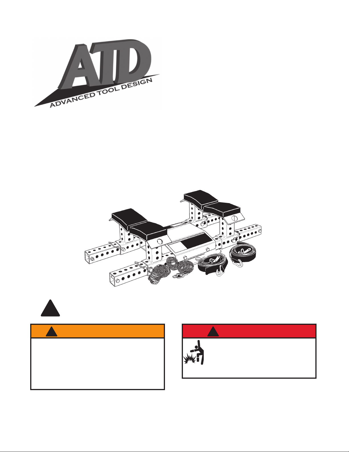
PRODUCT DESCRIPTION
This Fuel Tank Adapter is designed for fuel tank removal and fuel tank installation. This Fuel Tank Adapter must
ONLY be secured to ATD transmission jack model ATD-7430, ATD-7431. It is designed for use with passenger
cars and light trucks only. The Fuel Tank Adapter should only be used on METAL FUEL TANKS!
SPECIFICATIONS
Model Capacity
ATD-7470 80 lb. 40 gal. 32" x 15-3/8" x 9-1/4" 49 lb.
Risk of Explosion! Use of this product requires special skills and knowledge pertaining to grounding and
!
bonding of the components.
Ratchet
Max. Fuel Tank
Size
Use ONLY on METAL FUEL TANKS!
Bonding Cable
Base Plate
Product Size
( L x W x H)
Net Weight
Support Pad
Arm
Support Stand
Safety Nylon Strap
Figure 1 - Fuel Tank Adapter Components
2
Safety Snap Pin
Page 3
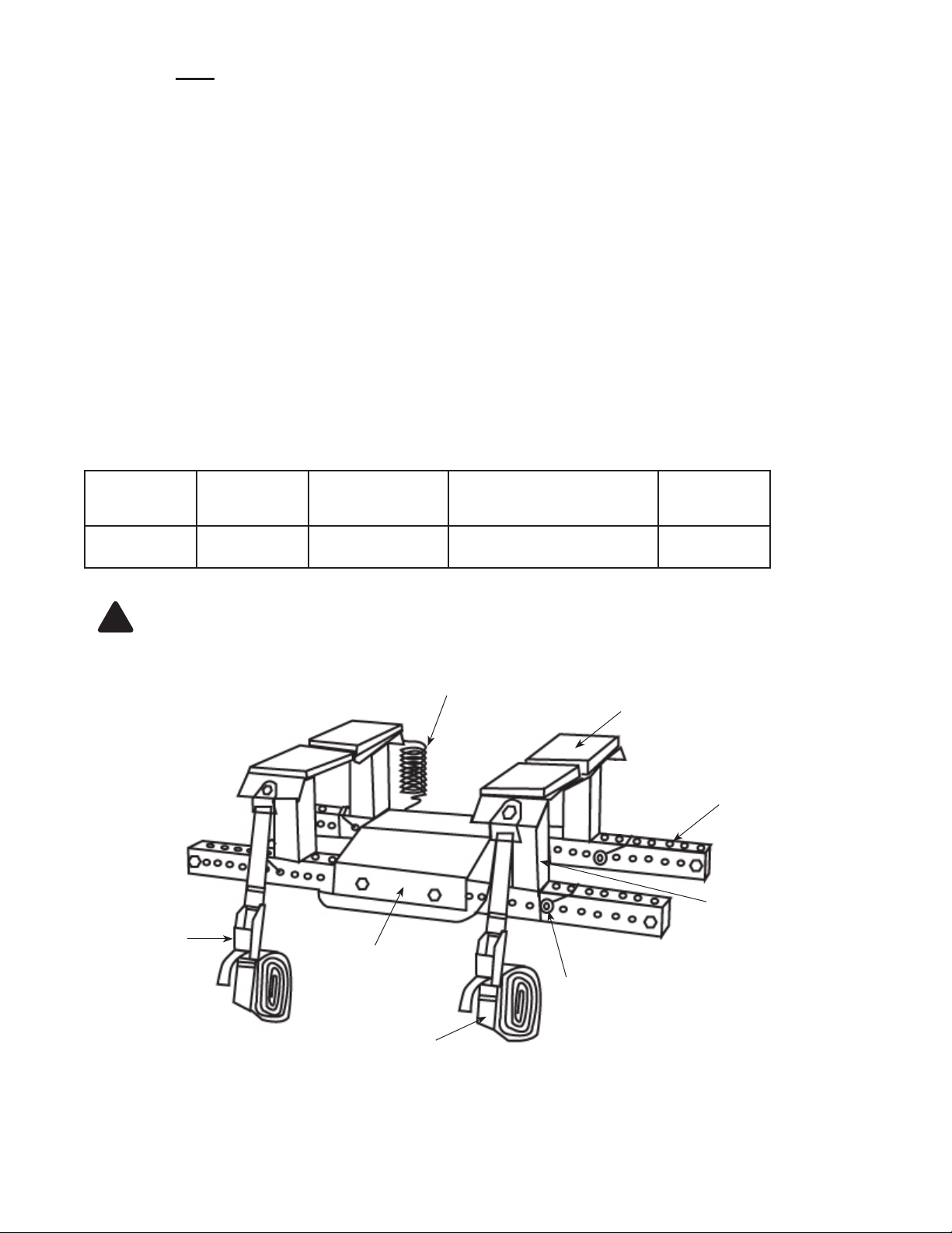
INSTALLATION (refer Figure 1 thru 5)
Note: Below instruction is illustrating the use of fuel tank adapter conjunction with Model ATD-7430, ATD-7431.
Estimated Time: 30 minutes
Tools required: Drill, 7/16" drill bit, 17mm & 19mm wrenches.
1. Remove saddle from the transmission jack.
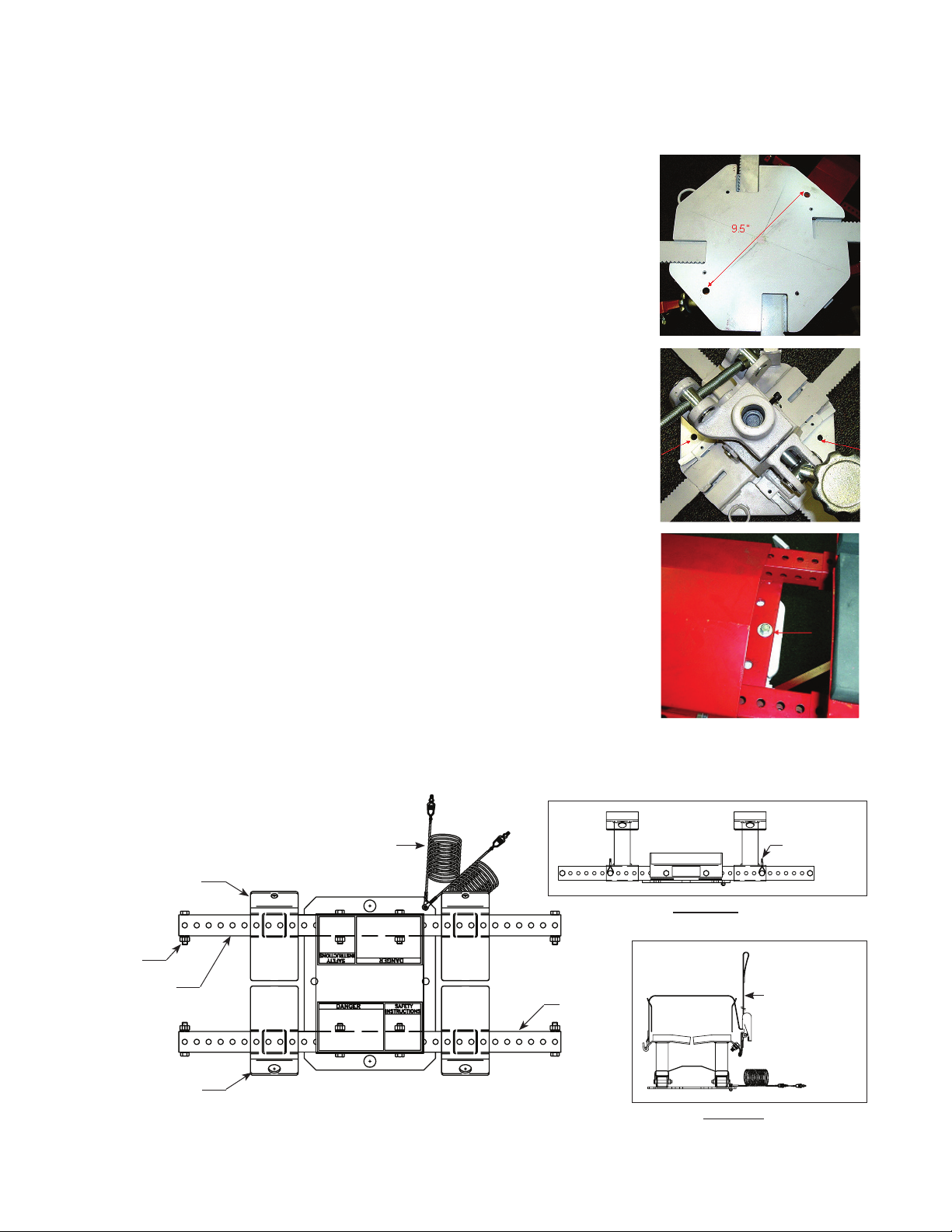
2. Drill two
7
/16” size holes on the saddle. Ensure the holes are 9
1/2" apart
and, should be located equally away from the saddle edges about 1”
(Refer gures 2 & 3 for location of holes).
Note: The integrity of your transmission jack should not be affected by
these two holes as long as the instructions are followed. ATDll warrant
its transmission jack original warranty for this specic fuel tank adapter
installation.
3. Secure the fuel tank adapter to the saddle with two 3/8”-24x1
1/2" bolts,
at washers, lock washers and nuts provided (Figure 4).
(Refer to Figure 5 for below procedures)
4. Slide support stand (1) over one end of the two arms (2). Repeat
procedure on other end of same arm; Slide support stand (3) over one
end of the other arm. Repeat procedure on other end of same arm.
5. Secure each support stand by inserting snap pin (4) through the aligned
holes on arm, snapping the latch over the end of pin as shown.
6. Insert the 3/8"-16 x 2 1/2" Bolt (5) through the last set of holes in arm and
secure in place with washers, lockwasher and nut provided. Repeat for
other three sides.
7. Secure both bonding cables (6) to the top side of frame base with
1
/4"-20x1" bolt and nut provided.
Note: Remove paint from top and bottom of plate around the
1
/4" diameter
hole.
8. Bolt safety nylon strap (7) to support stand (3). Secure with 1/2"-13x1"
bolt, washer, lockwasher and nut provided. Repeat procedure on other
support stand.
9. The assembly is now ready to use.
Fig. 2
Fig. 3
Fig. 4
Support Stand (3)
Bolt (5)
Arm (2)
Support Stand (1)
Bonding Cable (6)
Figure 5 - Assembly instruction
(4) Snap Pin
Front View
(2) Arm
Side View
(7) Safety Strap
3
Page 4

BEFORE USE
1. Verify that the product and the application are compatible.
2. Before using this product, read this fuel tank adapter manual, the transmission jack manual, and the vehicle
service manual completely. Familiarize yourself thoroughly with the product, its components, and recognize the
potential hazards associated with its use.
3. Locate and place a Class B re extinguisher near the working area.
4. Afx the fuel tank adapter to transmission jack properly before removing or installing the fuel tank.
5. Bond the Fuel Tank Adapter to the transmission jack and to the fuel tank while grounding the transmission jack
to earth before removing or installing the fuel tank. Operator must be bonded to both the jack and tank! If
unsure how to provide proper grounding and bonding of personnel and equipment STOP, discontinue use, and
seek the advice of qualied personnel.
6. Replace worn or damaged parts and assemblies with factory authorized replacement parts only.
7. Inspect before each use. Do not use if bent, broken or cracked components are noted.
! DANGER
NO SMOKING!
• NEVER use fuel tank handler near open ame,
heat sources or spark inducing environments.
• ALWAYS have a Class B re extinguisher
available.
• Drain ALL fuel from the vehicle fuel tank into
an approved and grounded fuel storage tank.
NEVER drain or store fuel in an open container,
near open ames, heat sources, or spark
inducing environments.
• If the fuel tank is damaged during servicing,
STOP and discard the fuel tank.
• Use ONLY on METAL FUEL TANKS! Do not
use on plastic fuel tanks!
• FAILURE TO HEED THESE WARNINGS
COULD RESULT IN DEATH, PERSONAL
INJURY, AND/OR PROPERTY DAMAGE!
! WARNING
• Study, understand, and follow all instructions
provided with and on this device before use.
• Do not exceed rated capacity.
• Use the Fuel Tank Adapter only with ATD
transmission jack models:
ATD-7430, ATD-7430
• ALWAYS bond the fuel tank to the
jack and bond the transmission jack to the earth
using the two bonding cables provided.
• ALWAYS center fuel tank on the four support
pads.
• ALWAYS secure fuel tank to fuel tank adapter
using the provided safety nylon straps.
• The fuel tank and the Fuel Tank Adapter must be
completely lowered (transmission jack ram fully
retracted) before transporting.
• Do not use adapters or accessories that are not
provided initially. Only accessories supplied by
the manufacturer can be used.
• Do not modify this device.
• Failure to heed these markings may result in
personal injury and/or property damage.
!
WARNING
!
• The paint on this product contains lead, a
chemical known in the State of California to cause
cancer, birth defects and other reproductive harm.
• Do not ingest paint chips and keep product
away from children.
• Wash hands after each use.
transmission
Operator must be bonded to both the jack and tank! If unsure how to provide proper bonding of
!
personnel and equipment STOP, discontinue use, and seek the advice of qualied personnel.
BEFORE USE
1. Verify that the product and the application are compatible, if in doubt call ATD Tech. Service.
2. Before using this product, read the operator's manual completely and familiarize yourself thoroughly with the
product and the hazards associated with its improper use.
3. Inspect before each use. Do not use if bent, broken or cracked components are noted.
4. Ensure that all parts move freely.
4
Page 5

OPERATION
Removal of Fuel Tank (Refer to Figure 6)
1. Read and follow the fuel tank removal/installation procedures as stated in the vehicle service manual.
2. Drain the existing fuel into an approved and grounded fuel storage tank.
3. Raise the transmission jack to directly underneath the designated fuel tank, refer to your transmission jack owner/
operator’s manual for instructions on how to raise and lower the transmission jack.
Operator must be bonded to both the jack and tank! If unsure how to provide proper bonding of
!
personnel and equipment STOP, discontinue use, and seek the advice of qualied personnel.
4. Clip one bonding cable to the fuel tank.
5. Clip the other bonding cable to the transmission jack.
6. Ground the transmission jack to earth.
7. Center the fuel tank on all four of the Fuel Tank Adapter padded supports. For adjustment,:
a.
Open the latch of the safety snap pin and remove.
b. Slide the support stand to the desired location.
c. Re-insert safety snap pins through the holes in both the support stand and arm. Close the latch of snap pin.
d. Adjust the opposite support stand to match the previously repositioned support stand.
e.
Ascertain that the load is centered with respect to
8. Place the safety nylon straps around the fuel tank, and hook them to the holes on the on support pads (refer to
Figure 6 and Figure 5 side view).
9. Securely tighten using the ratchet.
Note: To loosen the strap, pull the safety latch on the ratchet downward and rotate handle 180 degrees. When the
strap has been fully opened, the strap may be pulled through the ratchet to take up excess slack.
10. Ascertain that the hooks stay in place while tightening with the ratchet.
11. Remove fuel tank according to the vehicle service manual.
12. Lower the transmission jack to its lowest position before transporting the fuel tank.
the transmission jack.
Figure 6
5
Page 6

MAINTENANCE
Inspections should be made before each use of the Fuel Tank Adapter, checking for abnormal conditions.
1. It is important to keep the product clean.
2. Periodically wipe the product with an oily cloth.
3. Inspect the product annually.
Storage
Store the fuel tank adapter in a clean, dry area when not in use.
Paint contains lead!
!
DO NOT sand or grind painted surface!
TROUBLESHOOTING
Symptom Possible Causes Corrective Action
A vertical arm will not reposition Bent parts Contact Customer Service
The fuel tank does not maintain
steadiness while on the adapter
The adapter is shaky or feels
loose
Loose support pad Contact Customer Service
Components are worn or loose
Check, replace, and tighten
components and fasteners
ONE YEAR LIMITED WARRANTY
For a period of one (1) year from date of purchase, ATD Tools Inc. will repair or replace, at its option, without
charge, any of its products which fails due to a defect in material or workmanship under normal usage. This limited
warranty is a consumer's exclusive remedy.
Performance of any obligation under this warranty may be obtained by returning the warranted product,
freight prepaid, to ATD Tools Inc. Warranty Service Department, 160 Enterprise Drive, Wentzville, MO 63385.
Except where such limitations and exclusions are specically prohibited by applicable law, (1) THE
CONSUMER'S SOLE AND EXCLUSIVE REMEDY SHALL BE THE REPAIR OR REPLACEMENT OF DEFECTIVE
PRODUCTS AS DESCRIBED ABOVE. (2) ATD Tools Inc. SHALL NOT BE LIABLE FOR ANY CONSEQUENTIAL
OR INCIDENTAL DAMAGE OR LOSS WHATSOEVER. (3) ANY IMPLIED WARRANTIES, INCLUDING WITHOUT
LIMITATION THE IMPLIED WARRANTIES OF MERCHANTABILITY AND FITNESS FOR A PARTICULAR
PURPOSE, SHALL BE LIMITED TO ONE YEAR, OTHERWISE THE REPAIR, REPLACEMENT OR REFUND AS
PROVIDED UNDER THIS EXPRESS LIMITED WARRANTY IS THE EXCLUSIVE REMEDY OF THE CONSUMER,
AND IS PROVIDED IN LIEU OF ALL OTHER WARRANTIES, EXPRESS OR IMPLIED. (4) ANY MODIFICATION,
ALTERATION, ABUSE, UNAUTHORIZED SERVICE OR ORNAMENTAL DESIGN VOIDS THIS WARRANTY AND
IS NOT COVERED BY THIS WARRANTY.
Some states do not allow limitations on how long an implied warranty lasts, so the above limitation may not
apply to you. Some states do not allow the exclusion or limitation of incidental or consequential damages, so the
above limitation or exclusion may not apply to you. This warranty gives you specic legal rights, and you may also
have other rights which vary from state to state.
6
Page 7

Replacement Parts List for ATD-7470
REPLACEMENT PARTS
Not all components of the Fuel Tank Adapter are replacement items, but are illustrated as a convenient reference
of parts location. When ordering parts, give part number and parts description. Call or write for current pricing: ATD
Tools Inc. 160 Enterprise Drive, Wentzville, MO 63385. Tel:(636)327-9050 Fax:(636)327-9044
Item Part# Description Qty.
1 247552 Safety Snap Pin 4
2 247554 Bonding Cable Assembly 2
3 247576 Foam Pad/ Foot Assembly (1" Hole) 2
4 247578 Safety Tension Strap 2
5 247754 Foam Pad/ Foot Assembly (1/2" Hole) 2
6 247760 Hardware Kit 1
7 ATD7470-L0 Label 1
8 ATD7470-M0 Manual 1
3
5
1
4
2
Figure 7 - Replacement Parts Illustration for ATD-7470
ATD Tools Inc.
160 Enterprise Drive,
Wentzville MO 63385
636-327-9050
7
 Loading...