

Page 1
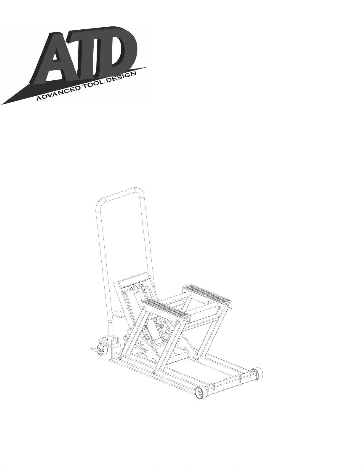
Motorcycle/A TV Lift
Operating Instruction & Parts Manual
Model Number
Atd-7460
Capacity
1500 Lbs
For Customer Service Contact
Atd T ools Inc.
114 I-70 Trade Center Drive St. Peters, MO 63376
Tel: (636)272-9050 Fax: (636)272-9044
Printed in China
OIPM # 7460-099
Page 2
SAVE THESE INSTRUCTIONS
!
For your safety please read, understand and follow the information contained within before use. The owner and
operator shall have an understanding of this product and safe operating procedures before attempting to use.
Instructions and safety information shall be conveyed in the operators native language before use is authorized.
Make certain that the operator thoroughly understands the inherent dangers associated with the use and
misuse of the product. If any doubt exists as to the safe and proper use of this device as outlined in this
factory authorized manual, remove the lift from service until safe and proper use is clearly understood.
!
INTENDED USE
This lift is specifically designed to lift and support up to rated capacity loads consisting of a single Motorcycle,
ATV, Snowmobile, Water Craft or Riding Lawn Mower whose frames are compatible with the lifting members of
the lift.
Incompatibility is evident when the loaded motorcycle, ATV, etc wobbles, feels unstable, and/or does not set
securely on the lift’s padded lift arms. Tying down incompatible loads will not make the loads secure and may
cause unexpected loss of load resulting in personal injury and/or property damage. These lifts are NOT
suitable for lifting, leveling and/or positioning cars, trucks, SUV’s or conveyances other than those specifically
listed and approved above. These lifts are NOT suitable for lifting, leveling and/or positioning houses,
construction trailers and dwellings in general. This product does not contain independent lifting devices, but is
designed to be permanently assembled. Hydraulic unit is not to be used independently of the motorcycle lift.
Study, understand and follow all printed materials provided with and on this device. Do not exceed rated
capacity. Ensure load is compatible with lift’s lifting pad. Center load on lift pads. After lifting load to desired
height, ensure lift arm locking mechanism is engaged. Secure load to lift using apropriate straps. Engage
locking caster mechanism before working on or around loaded lift. Move loaded lift over smooth, level, seamless surfaces only. Before moving, ensure load has been lowered completely. Use only on hard, level surfaces
capable of sustaining rated capacity loads. Lift only on areas of the load as specified by it’s manufacturer. Do
not alter this product in any way. Do not use for any purpose other than that for which this device is intended.
Failure to heed these messages may result in personal injury and/or property damage.
!
W ARNING
!
!
!
2
SPECIFICATIONS:
Rated Capacity; 1500 lbs.
Min. Lift Height: 4-1/2”
Max. Lift Height: 16-1/2”
Net Weight: 83-3/4 lbs.
Page 3
!
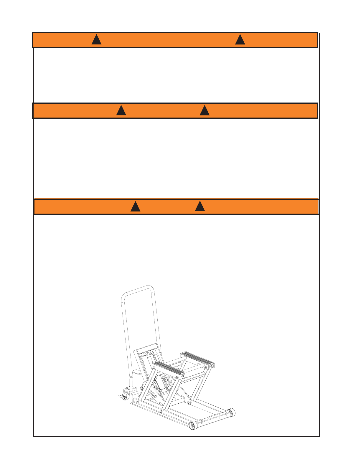
ASSEMBLY
1. Install hydraulic unit into receiver and secure with provided 7.5mm X 22mm bolt.
2. Install lift foot pedal into sleeve.
3. Install handle into frame and secure using the provided pins(2).
4. Ensure assembly rolls freely, lifts, locks, and lowers easily. Get to know how the release pedal, lift pedal,
and the height locking and unlocking mechanism work prior to loading the Lift.
INSPECT BEFORE EACH USE
!
Do not use if cracked, broken, bent or otherwise damaged parts are noted or if the lift is suspected to have been
subjected to a shock load. A shock load is caused by rapidly opening and closing the release valve while the lift
is loaded. Such operation may result in a hydraulic overload which may disable the hydraulic unit. Owner and
operators of this device shall be aware that no serviceable or replaceable parts are available for this device other
than those parts listed on page 4. Any lift that appears to be damaged in any way, is worn or operates abnormally shall be removed from service immediately until such time as repairs can be made.Do not attempt to weld,
rivet or otherwise repair this device. DO NOT modify or alter this device. It is recommended that an annual
inspection be done to this device by qualified persons and that missing or damaged labels, warning/safety
decals be replaced with ones that are factory authorized.
OPERATING INSTRUCTIONS
!
1. Position lift under appropriate lift point centering load on lift saddle.
2. Locate and pump the lift foot pedal until the lift saddle comes into contact with an appropriate
lift point.
3. Only after centering the load, slowly and carefully raise the lift arm by pumping the lift foot pedal.
4. Lock both swivel casters by pressing down on the caster lever marked ‘lock’.
5. Continue pumping until the load has reached desired height. Secure the load using appropriate tie down
means. Four tie down loops have been provided on the frame of the lift, 2 fore and 2 aft. Make sure that the
height locking mechansim is fully engaged before working on or around the loaded Lift.
6. To lower lift, disengage height locking lever and depress release pedal.
!
!
!
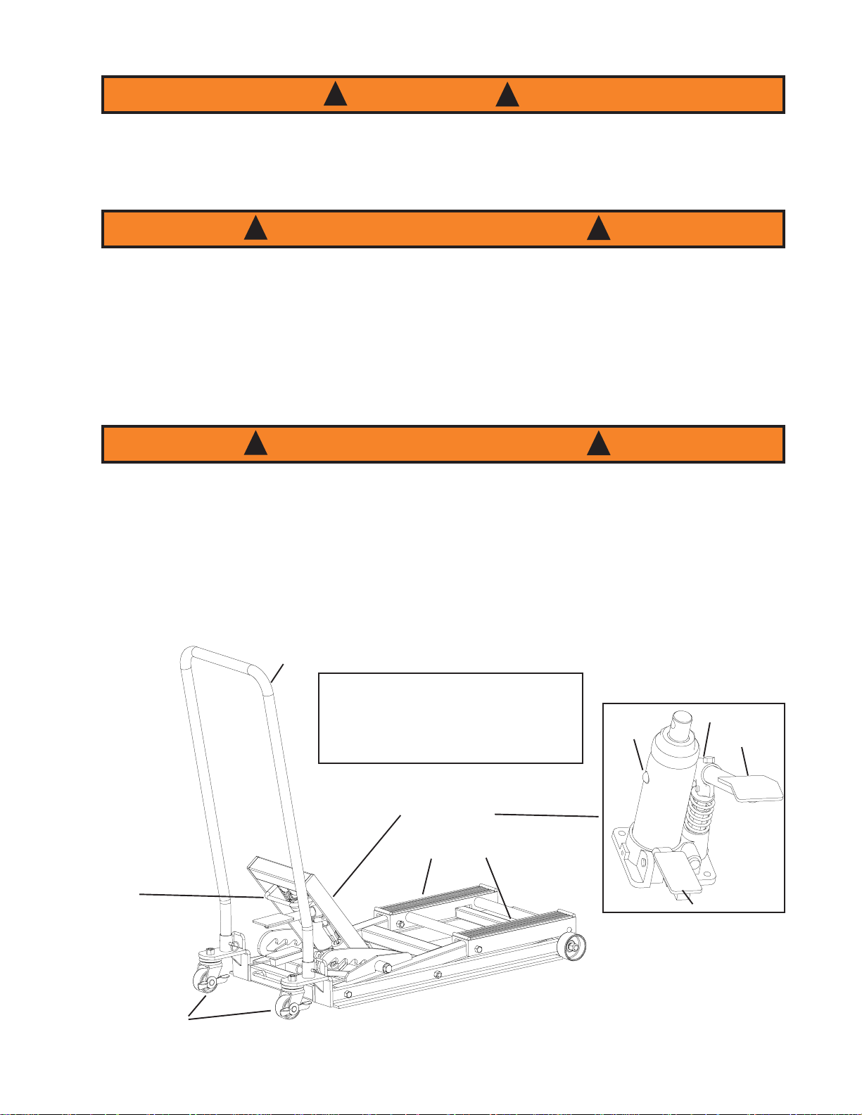
Handle
Press Height Locking Lever Forward
Against Hydraulic Unit to Engage
Locking Mechanism.
Pull Lever Back Over Lift Pedal
To Disengage Locking Mechanism
Height
Locking/Unlocking
Lever
Casters
3
KNOW YOUR LIFT
Hydraulic Unit
Lift Saddle
Oil Filler
Plug
Sleeve
Lift Pedal
Release Pedal
Page 4

!
CARE AND MAINTENENCE
NOTE: When lift is not in use, lifting arm should be stored in the fully retracted position. Keep lift clean and well
lubricated. Apply a couple of drops of light machine to all pivoting joints as needed. Thoroughly wipe up excess
oil to help prevent slipping and falling.
TO CHECK AND ADD HYDRAULIC OIL
!
1. To check hydraulic oil level, remove unit from lift, stand unit upright on a stable, level surface. Remove oil filler
plug. Oil should be to the level of the oil filler plug hole.
2. If low, add high quality hydraulic jack oil ONLY. Never use ANY other fluid. Use of other fluid may result in
hydraulic system failure, causing sudden and unexpected loss of load height.
3. Install oil filler plug, install hydraulic unit into receiver of lift. Secure with provided bolt.
NOTE: To get the longest life possible out of your lift, we recommend changing the hydraulic oil after 7 years of
use, sooner if used in a dust and grit filled environment. Do not expose to moisture. Dry lift completely if it gets
wet. Check pump piston and ram of hydraulic unit periodically for signs of rust and corrosion. Clean mildly
affected areas with a clean oily cloth. Never use abrasives on the pump piston and ram surfaces.
!
!
TO REPLACE HYDRAULIC OIL
!
1. Remove hydraulic unit from lift. Stand unit upright on a stable, level surface. Remove oil filler plug and drain
old oil into a suitable container.
2. Fill with high quality hydraulic jack oil.
NOTE: Dispose of used hydraulic oil in accordance with local regulations.
!
TO PURGE TRAPPED AIR FROM SYSTEM
1. Fully lower the lift arms, leave release valve open.
2. Remove oil filler plug. As you remove the oil filler plug you may hear a pressurized air escaping from the
reservoir. This means you have successfully purged trapped air from the system.
3. Install oil filler plug.
!
!
REPLACEMENT PARTS LIST
1. Front Wheel Assy. (1 ea.)
2. Rear Caster Assy. (1 ea.)
3. Hydraulic Unit Assy.
4. Locking Lever Assy.
5. Handle
6. Complete Hardware Kit (Not Shown)
Locking Lever Assy.
Handle
Hydraulic Unit Assy.
Rear Caster Assy.
4
Front Wheel Assy.
Page 5

TROUBLESHOOTING
Symptom
Hydraulic unit will not lift load
Hydraulic unit bleeds off after lift
Lift will not lower after unloading
Poor lift performance
Will not lift to full extension
Fluid level low
Possible Causes
Release valve not tightly closed
Overload condition
Release valve not tightly closed
Overload condition
Hydraulic unit malfunction
Reservoir overfilled
Linkages binding
Fluid level low
Air trapped in system
Corrective Action
Ensure release valve tightly closed
Remedy overload condition
Ensure release valve tightly closed
Remedy overload condition
Contact Atd Tools Tech. Service
Drain fluid to proper level
Clean and lubricate moving parts
Ensure proper fluid level
With ram fully retracted, remove oil filler
plug to let pressurized air escape, reinstall
oil filler plug
Ensure proper fluid level
1 YEAR LIMITED WARRANTY
For a period of 1 year from date of purchase, Atd T ools Inc. will repair or replace, at its option, without charge, any
of its products which fails due to a defect in material or workmanship, or which fails to conform to any implied
warranty not excluded hereby.
Performance of any obligation under this warranty may be obtained by returning the warranted product, freight
prepaid, to Atd T ools Inc. Warranty Service Department, 114 I-70 Trade Center Drive, St. Peters, MO 63376.
Except where such limitations and exclusions are specifically prohibited by applicable law. (1) the CONSUMER'S
SOLE AND EXCLUSIVE REMEDY SHALL BE THE REPAIR OR REPLACEMENT OF DEFECTIVE PRODUCTS
AS DESCRIBED ABOVE, and (2) Atd Tools Inc. SHALL NOT BE LIABLE FOR ANY CONSEQUENTIAL OR
INCIDENTAL DAMAGE OR LOSS WHATSOEVER, and (3) THE DURATION OF ANY AND ALL EXPRESSED AND
IMPLIED WARRANTIES, INCLUDING WITHOUT LIMITATION, ANY WARRANTIES OF MERCHANTABILITY AND
FITNESS FOR A PARTICULAR PURPOSE, IS LIMITED TO A PERIOD OF 1 YEAR FROM DATE OF PURCHASE.
Some states do not allow limitations on how long an implied warranty lasts, so the above limitation may not apply
to you. Some states do not allow the exclusion or limitation of incidental or consequential damages, so the above
limitation or exclusion may not apply to you. This warranty gives you specific legal rights, and you may also have
other rights which vary from state to state.
REPLACEMENT PARTS
When ordering replacement parts, please refer to the model number / serial number found on the product, then give
the part number and description.
Available Parts: (See Page 4) Not all components of the lift are replacement items, but are illustrated as a
convenient reference of location and position in the assembly sequence. Call or write for current pricing: Atd Tools
Inc. 114 I-70 Trade Center Drive, St. Peters, MO 73376
5
Tel. (636)272-9050 Fax (636)272-9044
Page 6

Atd T ools Inc.
114 I-70 Trade Center Drive St. Peters, MO 63376
Tel: (636)272-9050 Fax: (636)272-9044
Page 7

ATD TOOLS, INC.
PRODUCT SPECIFICATIONS
MODEL #: ATD7460
DESCRIPTION: HEAVY DUTY HYDRAULIC MOTORCYCLE LIFT
CAPACITY: 1500 LBS
PRODUCT DIMENSION: 34-7/8” (L) X 17-1/2 (W)
SADDLE MIN. HEIGHT: 4-1/2”
SADDLE MAX. HEIGHT: 16-1/2”
NET WEIGHT: 86.0 LBS
GROSS WEIGHT: 92.0 LBS
CARTON DIMENSION: 36-7/8" X 17-7/8" X 7"
CUFT.: 2.84 CUFT (336 PCs/ 20’ CTN)
FEATURES
• LIFTING RANGE: 4-1/2” TO 16-1/2”
• DUAL PEDAL POWER UNIT
• DUAL SAFETY LOCK MECHANISM
• EQUIPPED WITH A 14-3/4' X 1" TIE-
DOWN STRAP
Updated
August 18th, 2002
 Loading...