

Page 1
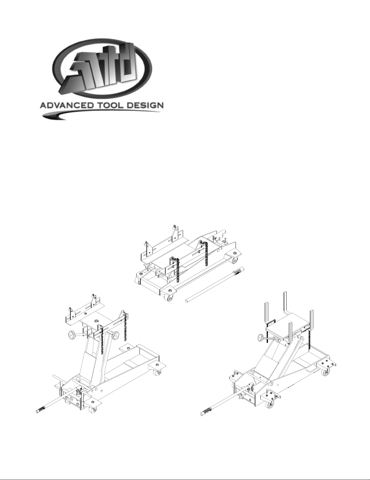
Hydraulic
Transmission
Jacks
Operating Instructions & Parts Manual
Model Number
Atd-7435
Atd-7436
Atd-7437
Capacity
1100 Lb.
2000 Lb.
3000 Lb.
Model Atd-7435
Model Atd-7436 Model Atd-7437
Atd Tools Inc.
160 Enterprise Drive, Wentzville MO 63385
ATD7435-M0
Printed in Taiwan
Page 2
Save these instructions
For your safety, read, understand, and follow the information provided with and on this jack. The owner and operator of
this equipment shall have an understanding of this jack and safe operating procedures before attempting to use. The
owner and operator shall be aware that use and repair of this product may require special skills and knowledge.
Instructions and safety information shall be conveyed in the operator's native language before use of this jack is
authorized. Make certain that the operator thoroughly understands the inherent dangers associated with the use and
misuse of the product. If any doubt exists as to the safe and proper use of this jack, remove from service immediately.
Inspect before each use. Do not use if broken, bent, cracked or damaged parts are noted. Any jack that appears
damaged in any way, or operates abnormally shall be removed from service immediately. If the jack has been or
suspected to have been subjected to a shock load (a load dropped suddenly, unexpectedly upon it), immediately
discontinue use until jack has been checked by an Atd Tools authorized service center. It is recommended that an
annual inspection be done by qualified personnel. Labels and Operator's Manuals are available from manufacturer.
PRODUCT DESCRIPTION
Atd Tools Hydraulic Transmission Jacks are designed to be used as an aid in the removal and installation of automotive
and light truck transmissions, transfer cases and transaxles. They are intended for use under an overhead lift or in a
garage pit. These jacks comply with applicable ASME-PALD Standards.
SPECIFICATIONS
Model Capacity Min. Height Max. Height Saddle Base
Atd-7435 1100 lb. 8 1/2" 24 3/4" 12 5/8" x 7 7/8" 17" x 9 3/8" 31 1/8" x 15"
Atd-7436 2000 lb. 7 7/8" 33 1/2" 14 1/4" x 8" 17" x 15 3/4" 39 3/8" x 19 1/8"
Atd-7437 3000 lb. 7 7/8" 37 1/4" 15 1/2" x 13 1/4" 24 7/8" x 19" 46 3/4" x 25 5/8"
CAUTION! Read carefully before unpacking product
SAFETY INSTRUCTIONS
BEFORE USE
1. Inspect jack before each use. Do not use if bent,
broken or cracked components are noted. Ensure
that casters move freely. Check for and tighten any
loose assemblies.
2. Verify that the product and the application are
compatible.
3. Remove oil filler plug/screw prior to initial use to
confirm oil level is at or just above the inner cylinder
as seen from the reservoir, fill as needed and
reinstall oil filler plug/screw.
• Study, understand, and follow all printed materials
provided with/on this product before use.
• Do not exceed rated capacity.
• Use only on hard, level surfaces capable of supporting
rated capacity loads.
• Use of this jack is limited to the removal, installation
and transportation of transmissions, transfer cases
and transaxles. Do not use a transmission jack to tilt
or support a vehicle.
• Ensure the center gravity of load is centered on the saddle.
• For your safety, do not exceed 100 tilt angle of the
saddle assembly in all directions.
• Adequately support the vehicle before starting repairs.
• Use only chains and slings provided.
• If loaded jack must be moved, make sure that the load
is secured, stable and in lowest position.
• This is a lifting and lowering device only.
• Transfer load immediately to appropriate support
device for service or repair.
• Shock loads may cause the sudden loss of load and/ or
cause the jack to tip or flip over violently, bend or break.
• No alterations shall be made on this product
• Failure to heed these markings may result in personal
injury and/or property damage.
2
Extended Saddle
Area
Base Size
! WARNING
Page 3
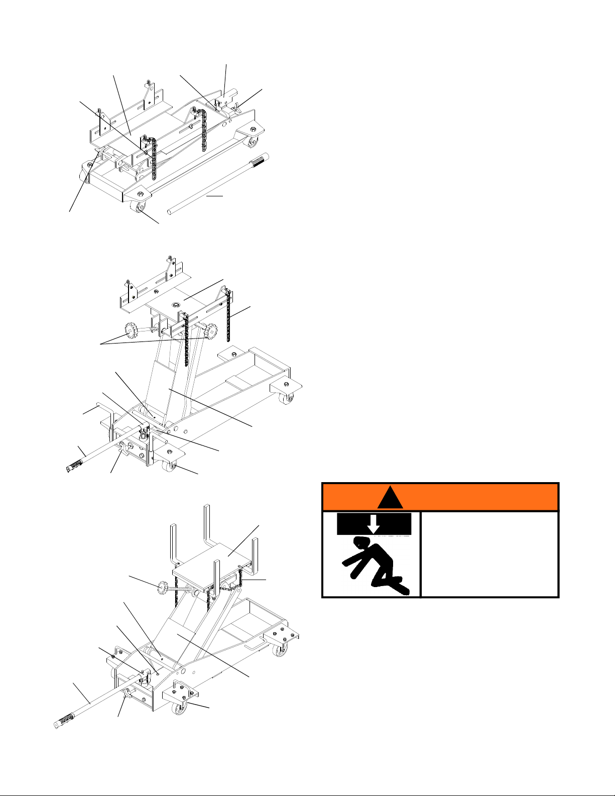
Saddle
Chain
Tilt Adjustment
Knob
Figure 1 - Model Atd-7435 Components
Oil Filler Plug
(not shown)
Caster
Handle Sleeve
Release Valve
Knob
Pump Handle
Saddle
ASSEMBLY
Little or no assembly is required. Refer to Figures in
the manual for details in understanding the assembly
and the components of your product.
OPERATION
Raise saddle:
1. Locate and close release valve by turning knob
clockwise firmly, then pump the pump handle until
the load is contacted.
2. Follow vehicle manufacturers recommended proce dures for removing the load as outlined in vehicle
service manual or repair guide.
3. Secure load with provided chains. Ensure load's
center of gravity is centered on the saddle and load
is stable before moving jack.
Tilt Adjustment
Knob
Grease Fitting Nipple
Handle Sleeve
Position
Handle
Pump Handle
Release Valve Knob
Figure 2 - Model Atd-7436 Components
Tilt Adjustment Knob
Grease Fitting Nipple
Oil Filler Plug
(not shown)
Caster
Chain
Lift Arm
Saddle
Chain
Lower saddle:
Caution! Be sure all tools and personnel are clear
before lowering load. Dynamic shock loads are created
by quickly opening and closing the release valve as the
load is being lowered. The resulting overload may
cause hydraulic system failure.
1. Slowly, gently turn the release valve knob
counterclockwise, never more than 1/2 full turn
until the load is completely lowered.
2. Immediately transfer the load to an appropriate
repair fixture.
! WARNING
To avoid crushing and related
injuries:
NEVER work on, under or
around a load supported only
by a jack. Immediately
transfer the load to an
appropriate work station.
Oil Filler Screw
Handle Sleeve
Pump Handle
Release Valve Knob
Figure 3 - Model Atd-7437 Components
Lift Arm
Caster
3
Page 4

MAINTENANCE
Important: Use only a good grade hydraulic jack oil. Avoid
mixing different types of fluid and NEVER use brake fluid,
turbine oil, transmission fluid, motor oil or glycerin.
Improper fluid can cause premature failure of the jack
and the potential for sudden and immediate loss of load.
We recommend Mobil DTE 13M or equivalent.
Adding oil
1. With saddle fully lowered, set jack in its upright,
level position. Remove oil filler plug/ screw.
2. Fill until oil is level with the oil filler hole, reinstall oil
filler plug/ screw.
Lubrication
A periodic coating of light lubricating oil to pivot points,
axles and hinges will help to prevent rust and assure
that wheels, casters and pump assemblies move freely.
Cleaning
Periodically check the ram for signs of rust or
corrosion. Clean as needed and wipe with an oily
cloth.
Note: Never use sandpaper or abrasive material on
these surfaces!
Changing oil
For best performance and longest life, replace the
complete fluid supply at least once per year.
1. With saddle fully lowered, set jack in its upright,
level position. Remove the oil filler plug/ screw.
2. Lay the jack on its side and drain the fluid into a
suitable container.
Note: Dispose of hydraulic fluid in accordance with
local regulations.
3. Set jack in its level upright position.
4. Fill with oil until just below the rim of oil filler hole.
5. Reinstall oil filler plug/ screw.
TROUBLESHOOTING
Storage
When not in use, store the jack with pump piston and
saddle in lowest position.
REPLACEMENT PARTS
Not all components of the jack are replacement items,
but are illustrated as a convenient reference of location
and position in the assembly sequence. When ordering
parts, give part number and the description on page 5
thru 7. Call or write for current pricing:
Atd Tools Inc. 160 Enterprise Drive, Wentzville, MO 63385.
Tel:(636)327-9050 Fax:(636)327-9044
Symptom
Jack will not lift load
Jack bleeds off after lift
Jack will not lower after unloading
Poor lift performance
Will not lift to full extension
Possible Causes
• Release valve not tightly closed
• Overload condition
• Release valve not tightly closed
• Overload condition
• Hydraulic unit malfunction
• Reservoir overfilled
• Linkages binding
• Fluid level low
• Air trapped in system
• Fluid level low
4
Corrective Action
• Ensure release valve tightly closed
• Remedy overload condition
• Ensure release valve tightly closed
• Remedy overload condition
• Contact Atd Tech. Service
• Drain fluid to proper level
• Clean and lubricate moving parts
• Ensure proper fluid level
• With ram fully retracted, remove oil filler
plug to let pressurized air escape, then
reinstall oil filler plug
• Ensure proper fluid level
Page 5

Replacement Parts for Model Atd-7435
Item Part# Description Qty
1 505-9-0092-207 Oil Filler Plug 1
2 450-1-100-108 Hydraulic Unit 1
3 451-6-6200-108 Chain 2
4 450-3-5000-100 Saddle Assembly 1
5 450-4-5300-108 Angle Bar 2
6 450-3-5700-108 Tilt Screw 1
7 450-3-5600-205 Saddle Holder 1
8 G89-0-9003-7002 Caster Assembly 4
9 450-6-4409-107 Hydraulic Unit Pivot Pin 2
10 G52-3-9903-104 Handle 1
11 450-4-1700-104 Release Valve Assembly 1
- 450-3-9901-107 Repair Kit for Hydraulic Unit -
- Atd7435-L0 Product Label -
- Atd7435-M0 Manual -
5
4
6
3
2
1
11
9
10
7
8
Figure 4 - Replacement Parts Illustration for Model Atd-7435
5
Page 6

Replacement Parts for Model Atd-7436
Item Part# Description Qty
1 505-9-0092-207 Oil Filler Plug 1
2 G52-1-1000-100 Hydraulic Unit 1
3 G36-6-7000-102 Chain 2
4 G52-3-4204-103 Saddle Assembly 1
5 G52-6-4207-107 Angle Bar 2
6 G52-6-4402-105 Tilt Screw 1
7 G52-6-4401-103 Tilt Screw 1
8 G52-6-1709-106 Tilt Knob 2
9 G52-3-4300-109 Saddle Holder 1
10 G52-4-5200-106 Caster Assembly 4
11 G52-3-9903-104 Handle 1
12 G52-6-1701-100 Release Valve 1
13 G34-6-1709-104 Release Valve Knob 1
14 G52-6-3004-108 Position Handle 1
15 653-1-0127-409 Hex. Bolt 6
16 653-1-0159-008 Hex. Bolt 1
- G52-3-9901-100 Repair Kit for Hydraulic Unit -
- Atd7436-L0 Product Label -
- Atd7435-M0 Manual 8
6
3
15
9
8
2
7
11
5
4
16
1
15
10
12
14
Figure 5 - Replacement Parts Illustration for Model Atd-7436
13
6
Page 7

Replacement Parts for Model Atd-7437
Item Part# Description Qty
1 324-4-1900-208 Oil Filler Screw 1
2 G62-1-1000-108 Hydraulic Unit 1
3 G36-6-7000-102 Chain 2
4 G52-4-4102-101 Hook & Chain 4
5 G62-3-4200-101 Saddle Plate 1
6 G62-6-4302-109 Support Bar 4
7 G62-6-4501-105 Tilt Screw 1
8 G52-6-1709-106 Tilt Knob 1
9 G62-3-4203-109 Saddle Holder 1
10 G38-4-5200-102 Caster Assembly 4
11 G46-6-2101-101 Handle 1
12 G62-6-1701-108 Release Valve 1
13 G34-6-1709-104 Release Valve Knob 1
14 653-1-0127-409 Hex. Bolt 6
- G62-3-9901-108 Repair Kit for Hydraulic Unit -
- Atd7437-L0 Product Label -
- Atd7435-M0 Manual -
6
9
5
8
7
4
3
11
1
2
10
12
13
14
Figure 6 - Replacement Parts Illustration for Model Atd-7437
7 ATD7435-M0
Page 8

ONE YEAR LIMITED WARRANTY
For a period of one (1) year from date of purchase, ATD Tools Inc. will repair or replace, at its option, without
charge, any of its products which fails due to a defect in material or workmanship under normal usage. This limited
warranty is a consumer's exclusive remedy.
Performance of any obligation under this warranty may be obtained by returning the warranted product, freight
prepaid, to ATD Tools Inc. Warranty Service Department,160 Enterprise Drive, Wentzville, MO 63385.
Except where such limitations and exclusions are specifically prohibited by applicable law, (1) THE
CONSUMER'S SOLE AND EXCLUSIVE REMEDY SHALL BE THE REPAIR OR REPLACEMENT OF DEFECTIVE
PRODUCTS AS DESCRIBED ABOVE. (2) ATD Tools Inc. SHALL NOT BE LIABLE FOR ANY CONSEQUENTIAL OR
INCIDENTAL DAMAGE OR LOSS WHATSOEVER. (3) ANY IMPLIED WARRANTIES, INCLUDING WITHOUT LIMITATION
THE IMPLIED WARRANTIES OF MERCHANTABILITY AND FITNESS FOR A PARTICULAR PURPOSE, SHALL BE
LIMITED TO ONE YEAR, OTHERWISE THE REPAIR, REPLACEMENT OR REFUND AS PROVIDED UNDER THIS
EXPRESS LIMITED WARRANTY IS THE EXCLUSIVE REMEDY OF THE CONSUMER, AND IS PROVIDED IN LIEU
OF ALL OTHER WARRANTIES, EXPRESS OR IMPLIED. (4) ANY MODIFICATION, ALTERATION, ABUSE,
UNAUTHORIZED SERVICE OR ORNAMENTAL DESIGN VOIDS THIS WARRANTY AND IS NOT COVERED BY THIS
WARRANTY.
Some states do not allow limitations on how long an implied warranty lasts, so the above limitation may not
apply to you. Some states do not allow the exclusion or limitation of incidental or consequential damages, so the above
limitation or exclusion may not apply to you. This warranty gives you specific legal rights, and you may also have other
rights which vary from state to state.
Atd Tools Inc.
160 Enterprise Drive,
Wentzville MO 63385
636-327-9050
 Loading...