

Page 1
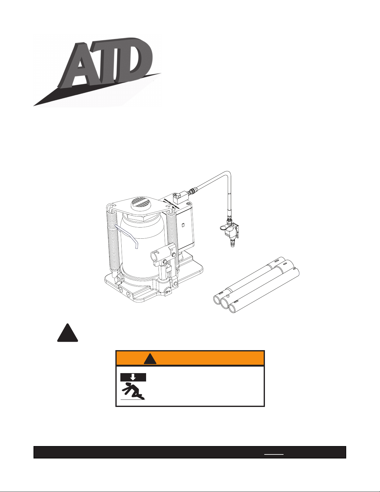
Hydraulic
Air/Manual Bottle Jacks
Operating Instructions & Parts Manual
Model Number
ATD7421
ATD7422
U.S. Patent No.'s. 5,341,723 - 5,946,912
Capacity
12 Ton
20 Ton
This is the safety alert symbol. It is used to alert you to potential personal injury hazards.
Obey all safety messages that follow this symbol to avoid possible injury or death.
!
! WARNING
To avoid crushing and related injuries:
NEVER work on, under or around a
load supported only by a hydraulic jack.
ALWAYS use a pair of adequately rated
jack stands.
ATD Tools Inc.
160 Enterprise Drive, Wentzville, MO 63385
Read this manual and follow all the Safety Rules and Operating Instructions before using this product.
Printed in China
ATD7421-M0-0113
Page 2

SAFETY AND GENERAL INFORMATION
Save these instructions. For your safety, read, understand, and follow the information provided with and on this
device before using. The owner and/or operator shall have an understanding of the device, its operating characteristics
and safety operating instructions before operating the equipment. The owner and/or operator shall be aware that use
and repair of this product may require special skills and knowledge. Instructions and safety information shall be read
to and discussed with the operator in the operator's native language, making sure that the operator comprehends
their contents, before use of this equipment is authorized. If any doubt exists as to the safe and proper use of this
device, remove from service immediately.
Inspect before each use. Do not use if abnormal conditions such as cracked welds, damaged, loose or missing
parts are noted. Any equipment that appears damaged in any way, is found to be worn, or operates abnormally shall
be removed from service until repaired. If the equipment has been or is suspected to have been subjected to an
abnormal load or shock, immediately discontinue use until inspected by a factory authorized repair facility (contact
distributor or manufacturer for list of authorized repair facilities). It is recommended that an annual inspection be
made by an authorized repair facility. Labels and Operator's Manuals are available from the manufacturer.
PRODUCT DESCRIPTION
ATD Tools Air Hydraulic Bottle Jacks are designed to lift rated capacity loads consisting of one end of a vehicle.
Immediately after lifting, the load must be supported by a pair of appropriately rated jack stands. Ensure that air
source can dedicate 7.8 CFM @ 110-175 psi to each jack operated. A minimum of 150 psi air pressure is required
to raise rated capacity load.
WARNING: Never use a hydraulic jack as a stand alone support device. After lifting, immediately support the
!
vehicle with appropriately rated jack stands. Never place any portion of your body under the vehicle when lifting
or lowering.
PREPARATION
Before Use
1. Before using this product, read the operator's manual completely and familiarize yourself thoroughly with the
product, its components and recognize the hazards associated with its use.
2. Verify that the product and application are compatible, if in doubt call Technical Service (816) 891-6390.
3. Assemble handle, ensure spring clips align with slots.
4. To familiarize yourself with basic operation, use the notched end of provided handle to engage and turn the release
valve:
a. Clockwise until rm resistance is felt to further turning. This is the ‘CLOSED’ release valve position used to
raise the ram plunger.
b. Counter-clockwise, but no more than 1 turn from the closed position. This is the ‘OPEN’ release valve position
used to lower the ram plunger.
5. With saddle fully lowered, and release valve closed, pump the operating handle. If ram responds immediately,
jack is ready for use. If jack does not respond, follow Bleeding/Venting Trapped Air procedure below.
6. Pour a teaspoon of good quality, air tool lubricant into the air supply inlet of the lift control valve. Connect to air
supply and squeeze lift control valve for 3 seconds to evenly distribute lubricant.
NOTICE: This product is equipped with the popular 1/4" NPT air coupler. When installing a different air coupler
of your choice, ensure that thread tape or compound is used when servicing connections. To ensure dependable,
trouble free operation an in-line air dryer and oiler is recommended.
7. Check that the pump operates smoothly and that the extension screw adjusts up/down easily before putting into
service. Replace worn or damaged parts and assemblies with genuine ATD Tools replacement parts only.
Bleeding/Venting Trapped Air
With the release valve in the OPEN position (4b above) and with ram plunger fully lowered, locate and remove the
air vent screw/ller plug. Insert the handle into the handle sleeve, then pump 6 to 8 full strokes. This will help release
any pressurized air which may be trapped within the reservoir. Oil level should be even with the bottom of the oil
ller hole. Reinstall the air vent screw/ller plug.
2
Page 3
! WARNING
• Study, understand, and follow all instructions
before operating this device.
• Do not exceed rated capacity.
• Use only on hard, level surface.
• This is a lifting device only. Immediately after
lifting, support the load with appropriate means.
! WARNING
X
To avoid crushing and related injuries:
•
Never work on, under or around a load supported
only by hydraulic jack.
• Lift only on areas of the vehicle as specied by
the vehicle manufacturer.
• No alterations shall be made to this product.
• Only attachments and/or adapters supplied by
the manufacturer shall be used.
• Failure to heed these markings may result in
personal injury and/or property damage.
SPECIFICATIONS
Model Capacity Base Size (L x W) Min. Height Max. Height
ATD7421 12 Ton 8-1/8" x 5-7/8" 9-5/8" 18-7/8"
ATD7422 20 Ton 9" x 6-3/4" 9-5/8" 18-7/8"
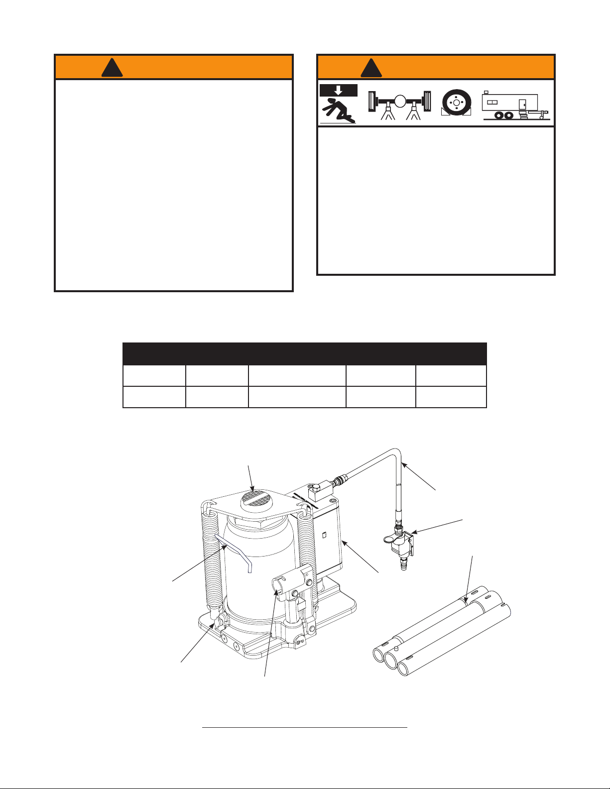
Saddle
• Chock unlifted tires in both directions.
• Do not use this device to lift, level, lower, support nor
move a house, mobile home, travel trailer, camper or
any building structure.
• Be alert and sober when using this product. Do not
operate under the inuence of drugs or alcohol.
Air Vent Screw/Filler Plug
(ref. Parts illustration for
location)
Carry Handle
Release Valve
Air Hose
Lift Control Valve
Handle
Air Motor
Handle Sleeve
Figure 1 - ATD7421 & ATD7422 Nomenclature
3
Page 4

OPERATION
Raising the Ram Plunger
1. Assemble handle, ensure that spring clips align with slots.
2. Place vehicle in park, with emergency brake on and wheels securely chocked to prevent inadvertent vehicle
movement.
3. Close release valve by turning handle clockwise until rm resistance is felt.
NOTICE: Always use the provided pump handle. The handle furnished with this jack will safely engage the release
valve and operate the Handle Sleeve. If handle is worn, operates abnormally, or will not positively engage the release
valve, discontinue use of the jack until a factory replacement handle can be acquired.
4. Verify lift point, center jack saddle under lift point.
WARNING: Never wire, clamp or otherwise enable the lift control valve to function by other than operator's
!
hand. Do not attempt operating pump by air and by handle simultaneously.
5. Squeeze the lift control valve or insert handle into handle sleeve and pump to contact lift point. To lift, continue
pumping until load reaches desired height.
6. Immediately transfer the load to a pair of appropriately rated jack stands.
NOTICE: Do not use extensions on air hose or operating handle.
Lowering
WARNING: Clear all tools and personnel before lowering load. Open release valve slowly. The further handle
!
is turned counter-clockwise, the faster the load will descend. Maintain control of the load at all times.
1. Raise load high enough to clear the jack stands, then carefully remove jack stands.
2. Slowly turn the handle counter-clockwise, but no more than 1/2 turn. If the load fails to lower:
a. Use another jack to raise the vehicle high enough to reinstall jack stands.
b. Remove the affected jack and then the stands.
c. Lower the load using the functioning jack.
3. After removing jack from under the load, push ram and handle sleeve down to reduce exposure to rust and
contamination.
MAINTENANCE
NOTICE: Use premium quality hydraulic jack oil. Avoid mixing different types of uid and NEVER use brake uid,
turbine oil, transmission uid, motor oil or glycerin. Improper uid can cause premature failure of the jack and the
potential for sudden and immediate loss of load.
Adding oil
1. With ram plunger fully lowered and pump piston fully depressed, set jack in its upright, level position. Remove air
vent screw/ller plug.
2. Fill with oil until just below the rim of the air vent screw/ller plug hole. Reinstall the air vent screw/ller plug.
Changing oil
For best performance and longest life, completely replace the uid supply at least once per year.
1. With ram plunger fully lowered and pump piston fully depressed, remove the air vent screw/ller plug.
2. Lay the jack on its side and drain the uid into a suitable container.
NOTICE: Dispose of hydraulic oil in accordance with local environmental regulations.
3. Fill with oil until just below the rim of the air vent screw/ller plug hole. Reinstall the air vent screw/ller plug.
4
Page 5

Lubrication
1. A periodic coating of light lubricating oil to pivot points, axles and hinges will help to prevent rust and assure that
pump assemblies move freely.
2. When used on a daily basis, air pump should be internally lubricated before each use. Use premium quality air
tool lubricant. If no inline oiler is used, pour a teaspoon of air tool oil into the inlet of the air control valve. Simply
operate the jack using the air feature in order to fully distribute the oil.
Cleaning
Periodically check the pump piston and ram plunger for signs of rust or corrosion. Clean as needed and wipe with
an oily cloth.
NOTICE: Do not use sandpaper or abrasive material on ram and pump piston surfaces.
Storage
When not in use, store the jack with pump piston and ram plunger fully retracted and air supply disconnected.
TROUBLESHOOTING
Symptom Possible Causes Corrective Action
• Release valve not tightly closed
Jack will not lift load
Jack will lift, but not maintain
pressure
Jack will not lower after
unloading
Poor lift performance
Will not lift to full extension • Fluid level low • Ensure proper uid level
• Overload condition
• Air pressure inadequate
• Release valve not tightly closed
• Hydraulic unit malfunction
• Reservoir overlled • Ensure load is removed, then drain
• Fluid level low
• Air trapped in system
• Ensure release valve tightly closed
• Remedy overload condition
• Ensure adequate air pressure
• Ensure release valve tightly closed
• Contact Tech. Service
uid to proper level
• Ensure proper uid level
• With ram fully retracted, remove oil
ller plug/screw to let pressurized
air escape, then reinstall oil ller
plug/screw
5
Page 6
18
14
16
15
17
20
39
22
25
21
23
24
26
27
28
4
5
6
7
9
10
11
12
3
2
1
36
37
48
34
33
32
31
30
29
38
8
40
19
13
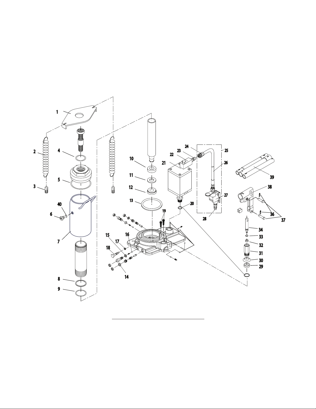
REPLACEMENT PARTS
Not all components of the jack are replacement items, but are illustrated as a convenient reference of location and
position in the assembly sequence. When ordering parts, give Model number, serial number and parts description
below. Call or write for current pricing: ATD Tools Inc. 160 Enterprise Drive, Wentzville, MO 63385.
Tel:(816)891-6390 Fax:(816)891-6599
Figure 2 - Replacement Parts Illustration
6
Page 7

Replacement Parts List for Models ATD7421
Item Part No. for ATD7421 Part No. for ATD7422 Description Qty
1 A240-10002-000 A200-10003-000 Cover 1
2 A200-10002-000 A200-10002-000 Extension Spring 2
3 A200-10004-000 A200-10004-000 Screw 2
4 * * O-ring 1
5 * * Gasket 1
6 5905-00100-200* G62S-03301-000* Air Vent Screw/Filler Plug 1
7 B12A-11000-000 B20A-11000-000 Reservoir Assy 1
8 * * Back-up Ring 1
9 * * O-ring 1
10 * * Ram Bearing 1
11 * * Back-up Ring 1
12 * * U-cup 1
13 * * Seal 1
14 * * O-ring 2
15 * * Special Washer 2
16 * * Steel Ball 6
17 * * Seal 1
18 BT10-24001-000 BT10-24001-000 Release Valve 1
19 B020-10003-000 B120-10003-000 Filter 2
20 * * Gasket 2
21 G831-03200-000 G831-03200-000 Air Motor Assy 1
22 A240-01000-000 A240-01000-000 Air Inlet Swivel 1
23 A240-02400-000 A240-02400-000 Quick-coupler, Male 1
24 A240-02300-000 A240-02300-000 Quick-coupler, Female 1
25 A240-02000-000 A240-02000-000 Hose Assy 1
26 A240-02100-000 A240-02100-000 Hose Assy 1
27 A240-02200-000 A240-02200-000 Air Inlet Control Valve 1
28 A240-02400-000 A240-02400-000 Quick-coupler, Male 1
29 * * Packing 1
30 B020-15002-000 B020-15002-000 Washer 1
31 B080-15001-000 B080-15001-000 Pump Cylinder 1
32 * * Oil Seal Assy 1
33 * * O-ring 1
34 A120-15101-000 A120-15101-000 Pump Piston 1
35 B10N-10004-000 B10N-10004-000 Rubber Pad 1
36 5405-02018-000 5405-02018-000 Snap Pin 2
37 5405-07027-000 5405-07027-000 Pin 2
38 B10N-14000-000 B10N-14000-000 Handle Sleeve Assy 1
39 B10N-21000-000 B10N-21000-000 Handle Assy 1
40 N/A * O-ring 1
* A2406S-053 A2006S-054 Repair Kit
& ATD7422
7
Page 8

ONE YEAR LIMITED WARRANTY
For a period of one (1) year from date of purchase, ATD Tools Inc. will repair or replace, at its option, without
charge, any of its products which fails due to a defect in material or workmanship under normal usage. This limited
warranty is a consumer's exclusive remedy.
Performance of any obligation under this warranty may be obtained by returning the warranted product, freight
prepaid, to ATD Tools Inc. Warranty Service Department, 160 Enterprise Drive, Wentzville, MO 63385, U.S.A.
Except where such limitations and exclusions are specically prohibited by applicable law, (1) THE
CONSUMER'S SOLE AND EXCLUSIVE REMEDY SHALL BE THE REPAIR OR REPLACEMENT OF DEFECTIVE
PRODUCTS AS DESCRIBED ABOVE. (2) ATD Tools Inc. SHALL NOT BE LIABLE FOR ANY CONSEQUENTIAL
OR INCIDENTAL DAMAGE OR LOSS WHATSOEVER. (3) ANY IMPLIED WARRANTIES, INCLUDING WITHOUT
LIMITATION THE IMPLIED WARRANTIES OF MERCHANTABILITY AND FITNESS FOR A PARTICULAR
PURPOSE, SHALL BE LIMITED TO ONE YEAR, OTHERWISE THE REPAIR, REPLACEMENT OR REFUND AS
PROVIDED UNDER THIS EXPRESS LIMITED WARRANTY IS THE EXCLUSIVE REMEDY OF THE CONSUMER,
AND IS PROVIDED IN LIEU OF ALL OTHER WARRANTIES, EXPRESS OR IMPLIED. (4) ANY MODIFICATION,
ALTERATION, ABUSE, UNAUTHORIZED SERVICE OR ORNAMENTAL DESIGN VOIDS THIS WARRANTY AND
IS NOT COVERED BY THIS WARRANTY.
Some states do not allow limitations on how long an implied warranty lasts, so the above limitation may not
apply to you. Some states do not allow the exclusion or limitation of incidental or consequential damages, so the
above limitation or exclusion may not apply to you. This warranty gives you specic legal rights, and you may also
have other rights, which vary from state to state.
ATD Tools Inc.
160 Enterprise Drive, Wentzville, MO 63385
8
Page 9

Hydrauliques
crics-bouteilles manuels
ou à air
Manual des consignes d'utilisation et des pièces
Modèles Capacité
ATD7421 10 886 kg (12 tonnes américaines)
ATD7422 18 144 kg (20 tonnes américaines)
Brevets américains nos 5,341,723 et 5,946,912
Voici le symbole signalant un danger pour la sécurité. Il est utilisé pour vous alerter
des dangers potentiels de blessures.
Respectez tous les messages de sécurité qui suivent ce symbole an d’éviter les
!
blessures et la mort.
! MISE EN GARDE
Pour éviter un écrasement et les blessures en lien avec celui-ci :
Ne travaillez JAMAIS autour d'une charge, en dessous d'elle
ou sur celle-ci, si elle est supportée seulement par un cric
hydraulique. Utilisez TOUJOURS une paire de béquilles de cric
dont la capacité nominale est adéquate.
ATD Tools Inc.
160 Enterprise Drive, Wentzville, MO 63385
Lisez ce manuel et observez toutes les consignes de sécurité et d'utilisation avant d'utiliser ce produit.
Imprimé en Chine
ATD7421-M0-0113
Page 10

INFORMATIONS GÉNÉRALES ET INFORMATIONS RELATIVES À LA SÉCURITÉ
Conservez ces instructions. Pour votre sécurité, lisez, comprenez et respectez toutes les consignes fournies
avec ce produit ou se trouvant sur celui-ci avant de l'utiliser. Le propriétaire, ainsi que l'utilisateur, doit comprendre
le fonctionnement du produit, ses caractéristiques de fonctionnement et les consignes de sécurité associées à son
utilisation avant de s'en servir. Ces personnes doivent aussi savoir que, pour utiliser ou réparer ce produit, il peut être
nécessaire d'avoir des connaissances ou des habiletés spéciales. Avant que l'utilisation de ce produit ne soit autorisée,
il faut lire, dans la langue maternelle de l'opérateur, les instructions et les informations relatives à la sécurité pour
qu'il en prenne connaissance et discuter de celles-ci avec lui, de manière à s'assurer qu'il les comprend. S'il y a des
doutes quant à la façon adéquate et sécuritaire de se servir du produit, il faut en cesser l'utilisation immédiatement.
Inspectez avant chaque utilisation. N'utilisez pas ce produit s'il est dans un état anormal, comme lorsqu'il y a des soudures
ssurées, des dommages ou des pièces manquantes ou mal xées. Tout équipement qui semble être endommagé d'une
quelconque façon, est usé ou fonctionne de manière anormale ne doit plus être utilisé jusqu'à ce qu'il soit réparé. Si le
produit a été soumis ou s'il y a des raisons de croire qu'il a été soumis à une charge ou à un choc anormal, cessez de
l'utiliser immédiatement jusqu'à ce qu'il soit inspecté à un centre de réparation autorisé par le fabricant (communiquez avec
le distributeur ou le fabricant pour avoir une liste des endroits autorisés). Il est recommandé qu'une inspection annuelle
soit faite à un centre autorisé. Il est possible de se procurer d'autres étiquettes et d'autres manuels auprès du fabricant.
DESCRIPTION DU PRODUIT
Les crics-bouteilles hydrauliques pneumatiques d'ATD Tools sont conçus pour soulever une charge égale à leur capacité
nominale, soit la masse d'une extrémité de véhicule. La charge doit être supportée par une paire de béquilles de cric à
capacité nominale adéquate immédiatement après le levage. Assurez-vous que la source d'air peut envoyer un débit de
0,22 m³/min à une pression allant de 758 à 1 206 kPa (7,8 pi³/min pour une pression de 110 à 175 po/lb²) à chaque cric utilisé.
Une pression minimale d'air de 1 034 kPa (150 po/lb²) est requise pour soulever une charge égale à la capacité nominale.
MISE EN GARDE : N'utilisez jamais un cric hydraulique comme seul dispositif de soutien. Après le levage,
!
faites reposer immédiatement le véhicule sur des béquilles de cric à capacité nominale adéquate. Ne placez
jamais une quelconque partie de votre corps sous le véhicule lorsque vous le soulevez ou l'abaissez.
PRÉPARATION
Avant l'utilisation
1. Avant d'utiliser ce produit, lisez le manuel d'utilisation au complet et familiarisez-vous parfaitement avec le produit
et ses composants, et identiez les dangers associés à son utilisation.
2. Vériez que le produit et son utilisation sont compatibles. Si vous avez des doutes, appelez le soutien technique
pour les produits au 1 816 891-6390.
3. Assemblez le levier et assurez-vous que les agrafes-ressorts sont alignées sur les fentes correspondantes.
4. An de vous familiariser avec le fonctionnement de base du cric, utilisez l'extrémité de la poignée de levage avec
une encoche pour enclencher et tourner la soupape de surpression :
a. Dans le sens horaire jusqu'à ce que vous sentiez une forte résistance au mouvement. C'est la position
« FERMÉE » de la soupape de surpression utilisée pour soulever le vérin à piston plongeur.
b. Dans le sens antihoraire, mais pas plus d'un tour à partir de la position fermée. C'est la position « OUVERTE »
de la soupape de surpression utilisée pour abaisser le vérin à piston plongeur.
5. Lorsque le point d'appui est complètement abaissé et que la soupape de surpression est fermée, pesez sur le
levier. Si le vérin à piston plongeur réagit immédiatement, le cric peut maintenant être utilisé. Si ce n'est pas le
cas, suivez les instructions de la section Purge de l'air emprisonné à la page 12.
6. Versez une cuillère à thé de lubriant de bonne qualité pour outil à air dans l'entrée de l'alimentation d'air de
la vanne de commande de levage. Branchez l'alimentation en air et ouvrez la vanne de commande de levage
pendant 3 secondes pour distribuer le lubriant de façon uniforme.
AVIS : Ce produit est doté du raccord populaire pour tuyau d'air 1/4 NPT. Lorsque vous installez un raccord pour
tuyau d'air de votre choix, assurez-vous d'utiliser du ruban pour joints letés ou du scellant lorsque vous faites
l'entretien des branchements. Il est recommandé d'utiliser un dessiccateur d'air en ligne et un huileur d'air en ligne
pour assurer un fonctionnement able sans problème.
7. Vériez que le levier fonctionne parfaitement et que la vis de rallonge peut être vissée ou dévissée facilement
avant d'utiliser le cric. Remplacez les pièces et les assemblages usés ou endommagés seulement par des pièces
de rechange ATD Tools.
10
Page 11

! MISE EN GARDE
• Lisez, comprenez et respectez toutes les
instructions avant d'utiliser ce produit.
• Ne dépassez pas la capacité nominale.
• Utilisez le produit seulement sur des surfaces
dures et de niveau.
• Cet appareil doit seulement être utilisé à des ns
de levage. Immédiatement après le levage, faites
en sorte que le véhicule soit supporté par un
moyen adéquat.
• Utilisez le cric seulement aux points de levage
indiqués par le fabricant du véhicule.
• Ne modiez pas ce produit.
• Utilisez seulement les accessoires et les
adaptateurs fournis par le fabricant.
• Le non-respect des consignes peut entraîner des
blessures ou des dommages matériels.
SPÉCIFICATIONS
Modèles Capacité Dimensions de la base (L x l) Hauteur min. Hauteur max.
! MISE EN GARDE
X
Pour éviter un écrasement et les blessures en lien
avec celui-ci :
•
Ne travaillez jamais autour d'une charge,
en dessous d'elle ou sur celle-ci, si elle est
supportée seulement par un cric hydraulique.
• Mettez des cales à l'avant et à l'arrière des pneus
non soulevés.
• N'utilisez pas cet appareil pour soulever, mettre
à niveau, abaisser, supporter ou déplacer une
maison, une maison mobile, une caravane
classique, une roulotte ou une structure d'édice.
• Soyez vigilant et sobre lorsque vous utilisez ce
produit. Ne vous en servez pas si vous avez
consommé de l'alcool ou de la drogue.
ATD7421
ATD7422
Vis de l'évent/bouchon
(consultez les dessins
des pièces pour leur
emplacement)
(12 tonnes américaines)
(20 tonnes américaines)
Poignée de
transport
Soupape de
surpression
10 886 kg
18 144 kg
Point d'appui
16,83 x 17,15 cm
(8-1/8 x 5-7/8 po)
12,7 x 12,07 cm
(9 x 6-3/4 po)
24,44 cm
(9-5/8 po)
24,44 cm
(9-5/8 po)
Moteur à air
47,94 cm
(18-7/8 po)
47,94 cm
(18-7/8 po)
Tuyau d'air
Vanne de
commande de
levage
Poignée
Douille de la poignée
Figure 1 : Pièces des modèles ATD7421 et ATD7422
11
Page 12

PRÉPARATION (suite)
Purge de l'air emprisonné
Lorsque la soupape de surpression est à la position OUVERTE (étape 4 b. à la page 10) et que le vérin à piston
plongeur est à son niveau minimal, trouvez et enlevez la vis de l'évent ou le bouchon. Insérez le levier dans la douille
de la poignée, puis abaissez et levez le levier le plus possible de six à huit fois. Cela va faciliter la libération de tout
air pressurisé pouvant être emprisonné dans le réservoir. Le niveau d'huile devrait se situer à la hauteur du fond du
trou de remplissage d'huile. Remettez la vis de l'évent ou le bouchon.
FONCTIONNEMENT
Soulever le vérin à piston plongeur
1. Assemblez le levier et assurez-vous que les agrafes-ressorts sont alignées sur les fentes.
2. Immobilisez le véhicule en serrant le frein de stationnement et en plaçant des cales à l'avant et à l'arrière des
roues pour empêcher les mouvements non désirés.
3. Fermez la soupape de surpression en tournant la poignée dans le sens horaire jusqu'à ce que vous sentiez une
bonne résistance.
AVIS : Utilisez toujours le levier fourni. Celui-ci permet d'enclencher la soupape de surpression et fait fonctionner la
douille de la poignée de manière sécuritaire. Si le levier est usé, fonctionne de manière anormale ou si la soupape
ne s'enclenche pas, cessez d'utiliser le cric jusqu'à ce vous ayez un levier de remplacement du fabricant.
4. Vériez le point de levage et centrez le point d'appui du cric sous celui-ci.
MISE EN GARDE : N'attachez et ne xez jamais la vanne de commande et ne faites jamais rien pour qu'elle
!
soit contrôlée d'une autre façon que par la main de l'opérateur. N'essayez pas d'utiliser la pompe sous
pression et manuellement de façon simultanée.
5. Ouvrez la vanne de commande de levage ou insérez le levier dans la douille de la poignée et abaissez et levez
le levier pour que le point d'appui entre en contact avec le point de levage. Pour soulever le véhicule, continuez
à abaisser et à lever le levier jusqu'à ce que la charge atteigne la hauteur désirée.
6. Faites reposer immédiatement la charge sur des béquilles de cric à capacité nominale adéquate.
AVIS : N'utilisez pas de rallonge avec le tuyau d'air ou le levier.
Abaisser
MISE EN GARDE : Avant d'abaisser la charge, assurez-vous qu'il n'y a aucun outil ni aucune personne en
!
dessous de celle-ci. Ouvrez la soupape de surpression lentement. Plus le levier est tourné dans le sens
antihoraire, plus la charge descend rapidement. Gardez le contrôle de la charge en tout temps.
1. Levez sufsamment la charge pour qu'elle ne soit plus en contact avec les béquilles de cric, puis enlevez ces
dernières.
2. Tournez lentement le levier dans le sens antihoraire, mais ne faites pas plus d'un demi-tour. Si la charge ne
descend pas :
a. Utilisez un autre cric pour soulever le véhicule sufsamment pour remettre les béquilles de cric.
b. Enlevez le cric défectueux et ensuite les béquilles de cric.
c. Abaissez la charge avec le cric qui fonctionne.
3. Après avoir retiré le cric, abaissez le vérin à piston plongeur et la douille de la poignée pour réduire l'exposition
à la rouille et aux contaminants.
ENTRETIEN
AVIS : Utilisez de l'huile pour cric hydraulique de première qualité. Évitez de mélanger différents types de liquides
et N'UTILISEZ JAMAIS de liquide pour frein, d'huile de turbine, de liquide de transmission, d'huile moteur ou de
glycérine. L'utilisation d'un liquide inapproprié peut entraîner une défaillance prématurée du cric et causer une chute
potentielle soudaine et immédiate de charge.
Ajouter de l'huile
1. Lorsque le vérin à piston plongeur est à son niveau minimal et que le piston du levier est enfoncé au maximum,
mettez le cric debout et à niveau. Enlevez la vis de l'évent ou le bouchon.
2. Mettez de l'huile jusqu'à ce que son niveau soit juste en dessous du rebord de la vis de l'évent ou du trou de
remplissage d'huile. Remettez la vis de l'évent ou le bouchon.
12
Page 13

Changer l'huile
An d'obtenir une performance et une durée de vie optimales, remplacez complètement l'huile au moins une fois par année.
1. Lorsque le vérin à piston plongeur est à son niveau minimal et que le piston du levier est enfoncé au maximum,
enlevez la vis de l'évent ou le bouchon de remplissage d'huile.
2. Posez le cric sur le côté et purgez le liquide en l'envoyant dans un contenant adéquat.
AVIS : Jetez l'huile hydraulique en respectant la réglementation environnementale locale.
3. Mettez de l'huile jusqu'à ce que son niveau soit juste en dessous du rebord de la vis de l'évent ou du trou de
remplissage d'huile. Remettez la vis de l'évent ou le bouchon.
Lubrication
1. Une lubrication périodique des points de pivotement, des axes et des charnières faite avec de l'huile légère aide
à prévenir la rouille et à assurer que les assemblages du levier bougent librement.
2. L'intérieur d'un cric pneumatique utilisé quotidiennement devrait être lubrié avant chaque utilisation. Utilisez un
lubriant de première qualité pour outil à air. S'il n'y a pas d'huileur d'air en ligne, versez une cuillerée à thé d'huile
pour outil à air dans l'entrée d'air de la vanne de commande de levage. Faites simplement fonctionner le cric à
l'air comprimé an de complètement distribuer l'huile.
Nettoyage
Inspectez périodiquement le piston du levier et le vérin à piston plongeur pour voir s'il y a de la rouille ou de la
corrosion. Nettoyez selon les besoins et essuyez avec un linge huileux.
AVIS : N'utilisez pas de papier sablé ni de matériau abrasif sur le piston du levier et le vérin à piston plongeur.
Stockage
Lorsque le cric n'est pas utilisé, rangez-le, le piston du levier et le vérin à piston plongeur devant être à leur niveau
minimal et l'alimentation en air débranchée.
DÉPANNAGE
Problème Causes possibles Mesure corrective
Cric ne soulevant pas la
charge
Cric soulevant la charge,
mais qui ne maintient pas
la pression
Cric ne descendant pas
après avoir enlevé la
charge
Performance de levage
médiocre
Système de levage ne
s'élevant pas au maximum
• Soupape de surpression qui
n'est pas bien fermée
• Surcharge
• Pression d'air incorrecte
• Soupape de surpression qui
n'est pas bien fermée
• Défaillance du vérin hydraulique
• Trop de liquide hydraulique dans
le réservoir
• Niveau de liquide bas
• Air emprisonné dans le système
• Niveau de liquide bas • Assurez-vous que le niveau de liquide est
• Assurez-vous que la soupape est bien
fermée
• Remédiez au problème de surcharge.
• Assurez-vous que la pression d'air est adéquate
• Assurez-vous que la soupape est bien
fermée
• Communiquez avec le soutien technique
Service
• Assurez-vous que la charge est enlevée, puis
purgez le liquide hydraulique pour qu'il soit au
bon niveau.
• Assurez-vous que le niveau de liquide est
adéquat.
• Avec le vérin complètement rétracté, retirez
le bouchon ou la vis de remplissage d'huile
pour vider l’excès d’air sous pression.
Remettez le bouchon ou la vis.
adéquat.
13
Page 14

PIÈCES DE RECHANGE
18
14
16
15
17
20
39
22
25
21
23
24
26
27
28
4
5
6
7
9
10
11
12
3
2
1
36
37
48
34
33
32
31
30
29
38
8
40
19
13
Ce ne sont pas toutes les pièces du cric qui peuvent être remplacées, mais elles sont illustrées pour montrer
leur emplacement ainsi que leur position pour l'assemblage. Lorsque vous commandez des pièces, fournissez le
numéro du modèle, le numéro de série et la description de la pièce. Pour connaître les prix actuels, appelez-nous
ou écrivez-nous : ATD Tools Inc. 160 Enterprise Drive, Wentzville, MO 63385. É.-U., téléphone : 1 816 891-6390,
télécopieur : 1 816 891-6599
Figure 2 - Illustration des pièces de rechange
14
Page 15

Liste de pièces de rechange pour les modèles ATD7421
et ATD7422
Pièce
1 A240-10002-000 A200-10003-000 Pièce supérieure du vérin 1
2 A200-10002-000 A200-10002-000 Ressort de traction 2
3 A200-10004-000 A200-10004-000 Vis 2
4 * * Joint torique 1
5 * * Ensemble de 1
6 5905-00100-200* G62S-03301-000* Vis de l'évent/bouchon 1
7 B12A-11000-000 B20A-11000-000 Assemblage du réservoir 1
8 * * Anneau de rechange 1
9 * * Joint torique 1
10 * * Palier de vérin à piston plongeur 1
11 * * Anneau de rechange 1
12 * * Joint en coupelle 1
13 * * Joint 1
14 * * Joint torique 2
15 * * Rondelle spéciale 2
16 * * Bille en acier 6
17 * * Joint 1
18 BT10-24001-000 BT10-24001-000 Soupape de surpression 1
19 B020-10003-000 B120-10003-000 Filtre 2
20 * * Ensemble de 2
21 G831-03200-000 G831-03200-000 Assemblage de moteur à air 1
22 A240-01000-000 A240-01000-000 Entrée d'air pivotante 1
23 A240-02400-000 A240-02400-000 Raccord rapide mâle 1
24 A240-02300-000 A240-02300-000 Raccord rapide femelle 1
25 A240-02000-000 A240-02000-000 Assemblage de tuyau 1
26 A240-02100-000 A240-02100-000 Assemblage de tuyau 1
27 A240-02200-000 A240-02200-000 Vanne de commande de levage à entrée d'air 1
28 A240-02400-000 A240-02400-000 Raccord rapide mâle 1
29 * * Garniture 1
30 B020-15002-000 B020-15002-000 Rondelle 1
31 B080-15001-000 B080-15001-000 Vérin du levier 1
32 * * Assemblage du joint pour huile 1
33 * * Joint torique 1
34 A120-15101-000 A120-15101-000 Piston du levier 1
35 B10N-10004-000 B10N-10004-000 Plateau porte-disque en caoutchouc 1
36 5405-02018-000 5405-02018-000 Goupille fendue 2
37 5405-07027-000 5405-07027-000 Goupille 2
38 B10N-14000-000 B10N-14000-000 Assemblage de la douille de la poignée 1
39 B10N-21000-000 B10N-21000-000 Assemblage de la poignée 1
40 S.O. * Joint torique 1
* A2406S-053 A2006S-054 Trousse de réparation
N° de pièce pour
modèle ATD7421
N° de pièce pour
modèle ATD7422
Description Qté
15
Page 16

GARANTIE LIMITÉE DE 1 AN
Pendant une période d'un (1) an, à partir de la date d'achat, ATD Tools Inc. réparera ou remplacera, à sa
discrétion, sans frais, tous ses produits qui, utilisés dans des conditions normales, sont défectueux à cause d'un
défaut de matériel ou de fabrication. Cette garantie limitée est le seul recours du consommateur.
Pour bénécier du service offert par la garantie, il faut retourner le produit couvert par celle-ci, port payé, à
ATD Tools Inc. Warranty Service Department, 160 Enterprise Drive, Wentzville, MO 63385, États-Unis.
Sauf dans les cas où les limitations et les exclusions décrites dans ce paragraphe sont spéciquement
interdites par la loi : (1) LE SEUL RECOURS DU CONSOMMATEUR EST DE FAIRE RÉPARER OU REMPLACER
LES PRODUITS DÉFECTUEUX COMME DÉCRIT CI-DESSUS; (2) ATD Tools Inc. NE SERA PAS TENUE
RESPONSABLE DES DOMMAGES CONSÉCUTIFS OU INDIRECTS OU DE PERTES QUELCONQUES; (3) TOUTE
GARANTIE IMPLICITE, CE QUI INCLUT SANS LIMITATION LES GARANTIES IMPLICITES DE COMMERCIALITÉ
ET D'ADAPTATION À UN USAGE PARTICULIER, SERA LIMITÉE À UN AN, À DÉFAUT DE QUOI LA RÉPARATION,
LE REMPLACEMENT OU LE REMBOURSEMENT, SELON CETTE GARANTIE EXPRESSE LIMITÉE, CONSTITUE
LE SEUL RECOURS DU CLIENT, ET REMPLACE TOUTE AUTRE GARANTIE, IMPLICITE OU EXPRESSE;
(4) TOUTE MODIFICATION, ALTÉRATION, UTILISATION ABUSIVE OU NON AUTORISÉE OU DÉCORATION
ORNEMENTALE ANNULE CETTE GARANTIE ET N'EST PAS COUVERTE PAR CELLE-CI.
Certaines provinces et certains États ne permettent pas de limiter la durée d'une garantie implicite et il
est donc possible que la limitation décrite ci-dessus ne s'applique pas. Certaines provinces et certains États ne
permettent pas d'exclure ou de limiter les dommages consécutifs ou indirects et il est donc possible que la limitation
ou l'exclusion mentionnée ci-dessus ne s'applique pas. Cette garantie vous confère des droits particuliers et il est
aussi possible que vous puissiez jouir d'autres droits qui varient d'une province à l'autre et d'un État à l'autre.
ATD Tools Inc.
160 Enterprise Drive, Wentzville, MO 63385
16
Page 17

Gatos hidráulicos
de botella
neumáticos/manuales
Manual de piezas e instrucciones de funcionamiento
Modelo Capacidad
ATD7421 12 toneladas (10886 kg)
ATD7422 20 toneladas (18144 kg)
Patente de EE. UU. N.º 5,341,723 - 5,946,912
Este es el símbolo de alerta de seguridad. Se usa para alertar sobre peligros potenciales
de lesiones personales.
Obedezca todos los mensajes de seguridad que tengan este símbolo, para evitar posibles
!
lesiones personales o la muerte.
! ADVERTENCIA
Para evitar lesiones por opresión y otras lesiones:
NUNCA trabaje sobre, debajo o alrededor de una
carga que solamente esté apoyada en un gato
hidráulico. SIEMPRE use un par de soportes para
gato de capacidad nominal adecuada.
ATD Tools Inc.
160 Enterprise Drive, Wentzville, MO 63385
Lea este manual y respete todas las reglas de seguridad y las instrucciones de funcionamiento
antes de usar este producto.
Impreso en China
ATD7421-M0-0113
Page 18

INFORMACIÓN GENERAL Y DE SEGURIDAD
Conserve estas instrucciones. Para su seguridad, lea, comprenda y siga la información que viene con este dispositivo
antes de su uso. El propietario u operador debe tener conocimientos sobre el dispositivo, sus características operativas
y las instrucciones para un funcionamiento seguro antes de utilizar el equipo. El propietario u operador debe tener
presente que el uso y la reparación de este producto podrían requerir habilidades y conocimientos especiales. Es
preciso leer y analizar las instrucciones y la información de seguridad con el operador, en su lengua materna, a n de
asegurarse de que el operador comprenda su contenido antes de recibir autorización para el uso de este equipo. Si
tiene dudas sobre el uso seguro y adecuado de este dispositivo, proceda a sacarlo de servicio de inmediato.
Inspeccione el dispositivo antes de cada uso. No use el dispositivo si presenta anomalías, como grietas en la
soldadura, o piezas dañadas, ojas o faltantes. Debe sacar de servicio todo equipo que presente daños, de la naturaleza
que fueren, esté gastado o funcione mal hasta su reparación. Si tiene la sospecha o la certeza de que el equipo fue
sometido a una carga o sufrió un impacto anormal, interrumpa el uso de inmediato hasta que sea controlado por un
centro de reparación autorizado por la fábrica (comuníquese con el distribuidor o fabricante para obtener una lista de los
centros de reparación autorizados). Se recomienda realizar una inspección anual a cargo de un centro de reparaciones
autorizado. Las etiquetas y los manuales del operador están disponibles por parte del fabricante.
DESCRIPCIÓN DEL PRODUCTO
Los gatos hidráulicos de botella ATD Tools accionados por aire están diseñados para levantar, cargas de capacidad
nominal que consisten en un extremo del vehículo. Inmediatamente después del levantamiento, la carga debe
apoyarse en un par de soportes para gato de capacidad nominal adecuada. Asegúrese de que la fuente de aire
pueda dedicar 7,8 CFM a 110-175 psi (7,5 a 12 bar) a cada gato en funcionamiento. Se requiere una presión de
aire mínima de 150 psi (10,3 bar) para aumentar la carga de capacidad nominal.
ADVERTENCIA: Nunca use un gato hidráulico como dispositivo de apoyo independiente. Luego de levantar
!
el vehículo, utilice los soportes para gato adecuados de inmediato. En ningún caso coloque ninguna parte del
cuerpo debajo del vehículo durante su ascenso o descenso.
PREPARACIÓN
Antes del uso
1. Antes de usar este producto, lea todo el manual del operador; procure familiarizarse en forma completa con el
producto y sus componentes, y reconocer los peligros asociados a su uso.
2. Verique que el producto y la aplicación sean compatibles; si tiene dudas, llame al Servicio técnico de al (816)
891-6390.
3. Instale la manija; asegúrese de que los sujetadores de resorte se alineen con las ranuras.
4. Para familiarizarse con el funcionamiento básico, use el extremo muescado de la manija provista para accionar
y girar la válvula de liberación:
a. A la derecha hasta que sienta una resistencia rme para continuar girando. Esta es la posición ‘CERRADO’
de la válvula de liberación que se usa para elevar el pistón del ariete.
b. A la izquierda, pero no más de 1 giro con respecto a la posición de cerrado. Esta es la posición ‘ABIERTO’ de
la válvula de liberación que se usa para bajar el pistón del ariete.
5. Una vez que el asiento haya descendido por completo y la válvula de liberación esté cerrada, bombee la manija
de funcionamiento. Si el ariete responde de inmediato, el gato está listo para ser usado. Si el gato no responde,
siga el procedimiento de la sección Purgado/descarga del aire atrapado en la pagína 20.
6. Vierta una cucharadita de lubricante para herramientas de aire de buena calidad en la entrada del suministro de
aire de la válvula de control de elevación. Conecte al suministro de aire y oprima la válvula de control de elevación
durante 3 segundos para distribuir el lubricante de manera uniforme.
AVISO: Este producto está equipado con el acoplador de aire común de 1/4" (0,6 cm) NPT. Cuando instale un
acoplador de aire que no sea el de su elección, asegúrese de usar cinta o compuesto aislante para la reparación de
las conexiones. Se recomienda el uso de un secador de aire y engrasador en línea para asegurar el funcionamiento
able y libre de problemas.
7. Compruebe que la bomba funcione sin dicultades y que el tornillo de extensión se ajuste fácilmente hacia arriba
y hacia abajo antes de ponerlo en servicio. Reemplace las piezas y los conjuntos desgastados o dañados solo
con piezas de repuesto genuinas de ATD Tools.
18
Page 19

! ADVERTENCIA
• Estudie, comprenda y siga todas las instrucciones
antes de poner en funcionamiento este dispositivo.
• No exceda la capacidad nominal.
• Utilícelo únicamente sobre supercies duras y
uniformes.
• Es solo un dispositivo para levantar cargas.
Inmediatamente después de levantar la carga,
utilice los soportes adecuados.
• Use solamente las áreas del vehículo
especicadas por el fabricante del vehículo.
• No deben hacerse modicaciones a este producto.
• Solo deben utilizarse accesorios y/o adaptadores
suministrados por el fabricante.
• Si no se respetan estas indicaciones, podrían
producirse lesiones personales o daños a la
propiedad.
ESPECIFICACIONES
Modelo Capacidad Tamaño de la base (L x P) Altura mín. Altura máx.
! ADVERTENCIA
X
Para evitar lesiones por opresión y otras lesiones:
•
Nunca trabaje sobre, debajo o alrededor de una
carga que solamente esté apoyada en un gato
hidráulico.
• Bloquee las ruedas sin elevar en ambas direcciones.
• No utilice este dispositivo para levantar, nivelar,
bajar, apoyar ni mover una casa, casa rodante,
remolque de viaje, camioneta “camper” u otra
estructura de construcción.
• Cuando utilice este equipo, procure estar atento y
sobrio. No use el equipo si está bajo los efectos de
drogas o bebidas alcohólicas.
ATD7421
ATD7422
Tapón/tornillo de la
purga de aire (consulte
Ilustración de piezas para
ver la ubicación)
Manija de
transporte
12 toneladas
(10886 kg)
20 toneladas
(18144 kg)
Asiento
8-1/8" x 5-7/8"
(16,83 x 17,15 cm)
9" x 6-3/4"
(12,7 x 12,07 cm)
Motor neumático
9-5/8"
(24,44 cm)
9-5/8"
(24,44 cm)
Manguera
de aire
18-7/8"
(47,94 cm)
18-7/8"
(47,94 cm)
Válvula de control
de elevación
Manija
Válvula de liberación
Manguito de la manija
Figura 1: Nomenclatura de ATD7421 & ATD7422
19
Page 20

PREPARACIÓN (cont.)
Purgado/descarga del aire atrapado
Coloque la válvula de liberación en la posición ABIERTO (4b en la pagína 18) y baje el pistón del ariete en forma
completa; luego, ubique y retire el tapón/tornillo de la purga de aire. Coloque la manija en el manguito de la manija;
luego bombee de 6 a 8 recorridos completos. Esto ayudará a liberar el aire presurizado que pudiera estar atrapado
dentro del depósito. El aceite debe estar a nivel con la parte inferior del oricio de llenado de aceite. Vuelva a colocar
el tapón/tornillo de la purga de aire.
FUNCIONAMIENTO
Elevación del pistón del ariete
1. Instale la manija; asegúrese de que los sujetadores de resorte se alineen con las ranuras.
2. Estacione el vehículo, con el freno de emergencia accionado y las ruedas rmemente bloqueadas para evitar el
movimiento accidental del vehículo.
3. Cierre la válvula de liberación; para hacerlo, gire la manija a la derecha hasta que sienta una resistencia rme.
AVISO: Use la manija de la bomba provista. La manija proporcionada con este gato se enganchará de manera
segura en la válvula de liberación y operará el manguito de la manija. Si la manija está desgastada, funciona de
manera anormal o no se engancha de manera positiva en la válvula de liberación, DETÉNGASE e interrumpa el
uso del gato hasta que pueda adquirirse una manija de reemplazo de la fábrica.
4. Verique el punto de elevación; centre el asiento del gato debajo del punto de elevación.
ADVERTENCIA: Nunca use cables ni abrazaderas ni active de otro modo la válvula de control de elevación
!
para que funcione de otra manera que no sea con la mano del operador. No intente hacer funcionar la
bomba por aire y con la manija al mismo tiempo.
5. Oprima la válvula de control de elevación o inserte la manija en el manguito de la manija y la bomba hasta que
toque el punto de elevación. Para la elevación, siga bombeando hasta que la carga alcance la altura deseada.
6. Transera inmediatamente la carga a un par de soportes para gato con la carga nominal adecuada.
AVISO: No utilice extensiones en la manguera de aire o la manija de funcionamiento.
Descenso
ADVERTENCIA: Despeje el área de herramientas y operarios antes de bajar la carga. Abra lentamente la
!
válvula de liberación. Cuanto más gire la manija a la izquierda, más rápido descenderá la carga. Mantenga el
control de la carga en todo momento.
1. Eleve la carga a una altura que permita despejar los soportes para gato, luego retire con cuidado dichos soportes.
2. Gire lentamente la manija a la izquierda, pero no más de 1/2 giro. Si la carga no desciende:
a. Use otro gato para elevar el vehículo a una altura que permita volver a instalar los soportes para gato.
b. Retire el gato afectado y, a continuación, los soportes.
c. Baje la carga utilizando el gato que funciona.
3. Luego de retirar el gato de la parte de abajo de la carga, baje el ariete y el manguito de la manija para reducir la
exposición al óxido y la contaminación.
MANTENIMIENTO
AVISO: Use aceite para gatos hidráulicos de alta calidad. Evite mezclar diferentes tipos de líquidos y NUNCA
use líquido de frenos, aceite de turbinas, líquido de transmisión, aceite de motor ni glicerina. El uso de un líquido
inadecuado puede provocar fallas prematuras en el gato y posibles pérdidas de carga repentinas e inmediatas.
Agregado de aceite
1. Una vez que el pistón del ariete haya descendido por completo y el pistón de la bomba se haya oprimido por
completo, coloque el gato en posición vertical y a nivel. Retire el tapón/tornillo de la purga de aire.
2. Llene con aceite hasta justo por debajo del borde del oricio del tapón/tornillo de la purga de aire. Vuelva a colocar
el tapón/tornillo de la purga de aire.
20
Page 21

Cambio de aceite
Para lograr el mejor rendimiento y una vida útil más prolongada, cambie por completo el suministro de líquido por
lo menos una vez al año.
1. Una vez que el pistón del ariete haya descendido por completo y el pistón de la bomba se haya oprimido por
completo, quite el tapón/tornillo de la purga de aire.
2. Coloque al gato de lado y descargue el líquido en un recipiente adecuado.
AVISO: Deseche el aceite hidráulico conforme a las reglamentaciones ambientales locales.
3. Llene con aceite hasta justo por debajo del borde del oricio del tapón/tornillo de la purga de aire. Vuelva a colocar
el tapón/tornillo de la purga de aire.
Lubricación
1. La lubricación periódica con un aceite liviano en los puntos de giro, los ejes y las bisagras ayudará a evitar la
corrosión y garantizará que los conjuntos de la bomba se muevan libremente.
2. Cuando se usa a diario, la bomba de aire debe lubricarse por dentro antes de cada uso. Use lubricante para
herramientas de aire de primera calidad. Si no se usa un engrasador en línea, vierta una cucharadita de aceite
para herramientas de aire en la entrada de la válvula de control de aire. Simplemente haga funcionar el gato
usando la función de aire para poder distribuir el aceite en forma completa.
Limpieza
Verique periódicamente el pistón de la bomba y el pistón del ariete en busca de signos de oxidación o corrosión.
Límpielos con un paño con aceite, según sea necesario.
AVISO: No use papel de lija ni materiales abrasivos en las supercies del ariete y el pistón de la bomba.
Almacenamiento
Cuando no lo utilice, guarde el gato con el pistón de la bomba y el pistón del ariete totalmente contraídos y el
suministro de aire desconectado.
LOCALIZACIÓN Y SOLUCIÓN DE PROBLEMAS
Síntoma Causas posibles Medidas correctivas
El gato no levanta la carga.
El gato se eleva, pero no
mantiene la presión.
El gato no baja después de
su descarga.
La capacidad de elevación
es deciente.
• La válvula de liberación no está
herméticamente cerrada.
• Hay un estado de sobrecarga.
• Presión de aire inadecuada
• La válvula de liberación no está
herméticamente cerrada.
• La unidad hidráulica no funciona
correctamente.
• El depósito está lleno en exceso. • Asegúrese de retirar la carga y descargue
• El nivel de líquido está bajo.
• Hay aire atrapado en el sistema.
• Asegúrese de que la válvula de liberación
• Solucione el estado de sobrecarga.
• Asegúrese de que la presión de aire sea
• Asegúrese de que la válvula de liberación
• Póngase en contacto con un técnico de
• Asegúrese de que el nivel de líquido sea
• Una vez que el ariete esté completamente
esté herméticamente cerrada.
adecuada.
esté herméticamente cerrada.
servicio. servicio técnico
el líquido hasta el nivel adecuado.
el adecuado.
contraído, quite el tapón/tornillo del
llenado de aceite para permitir la salida del
aire presurizado; luego, vuelva a instalar el
tapón/tornillo de llenado de aceite.
La elevadora no se eleva al
máximo de su capacidad.
• El nivel de líquido está bajo. • Asegúrese de que el nivel de líquido sea
el adecuado.
21
Page 22

PIEZAS DE REPUESTO
18
14
16
15
17
20
39
22
25
21
23
24
26
27
28
4
5
6
7
9
10
11
12
3
2
1
36
37
48
34
33
32
31
30
29
38
8
40
19
13
No todos los componentes del gato tienen reemplazo, pero se ilustran a modo de referencia práctica de la
ubicación y la posición que ocupan en la secuencia del conjunto. Cuando realice el pedido de piezas, indique el
número de modelo, el número de serie y la descripción de la pieza. Para obtener el precio vigente, comuníquese a:
ATD Tools Inc. 160 Enterprise Drive, Wentzville, MO 63385. U.S.A. Tel.: (816) 891-6390 Fax: (816) 891-6599
Figura 2: Ilustración de piezas de repuesto
22
Page 23

Lista de piezas de repuesto para el modelo ATD7421
y ATD7422
Elemento
1 A240-10002-000 A200-10003-000 Cubierta 1
2 A200-10002-000 A200-10002-000 Resorte de extensión 2
3 A200-10004-000 A200-10004-000 Tornillo 2
4 * * Junta tórica 1
5 * * Junta 1
6 5905-00100-200* G62S-03301-000* Tapón/tornillo de la purga de aire. 1
7 B12A-11000-000 B20A-11000-000 Conjunto del depósito 1
8 * * Anillo de respaldo 1
9 * * Junta tórica 1
10 * * Rodamiento del ariete 1
11 * * Anillo de respaldo 1
12 * * Copa en U 1
13 * * Sello 1
14 * * Junta tórica 2
15 * * Arandela especial 2
16 * * Bola de acero 6
17 * * Sello 1
18 BT10-24001-000 BT10-24001-000 Válvula de liberación 1
19 B020-10003-000 B120-10003-000 Filtro 2
20 * * Junta 2
21 G831-03200-000 G831-03200-000 Conjunto de motor neumático 1
22 A240-01000-000 A240-01000-000 Admisión de aire giratoria 1
23 A240-02400-000 A240-02400-000 Acoplador rápido, macho 1
24 A240-02300-000 A240-02300-000 Acoplador rápido, hembra 1
25 A240-02000-000 A240-02000-000 Conjunto de la manguera 1
26 A240-02100-000 A240-02100-000 Conjunto de la manguera 1
27 A240-02200-000 A240-02200-000 Válvula de control de admisión de aire 1
28 A240-02400-000 A240-02400-000 Acoplador rápido, macho 1
29 * * Empaque 1
30 B020-15002-000 B020-15002-000 Arandela 1
31 B080-15001-000 B080-15001-000 Cilindro de la bomba 1
32 * * Conjunto del sello de aceite 1
33 * * Junta tórica 1
34 A120-15101-000 A120-15101-000 Pistón de la bomba 1
35 B10N-10004-000 B10N-10004-000 Almohadilla de goma 1
36 5405-02018-000 5405-02018-000 Pasador de gancho 2
37 5405-07027-000 5405-07027-000 Pasador 2
38 B10N-14000-000 B10N-14000-000 Conjunto del manguito de la manija 1
39 B10N-21000-000 B10N-21000-000 Conjunto de manija 1
40 N/D * Junta tórica 1
* A2406S-053 A2006S-054 Kit de reparación
N.º de pieza para
el modelo ATD7421
N.º de pieza para
el modelo ATD7422
Descripción Cant.
23
Page 24

GARANTÍA LIMITADA DE UN AÑO
Por el período de un (1) año desde la fecha de compra, ATD Tools Inc. reparará o reemplazará, a su
discreción, sin costo alguno, cualquier producto que presente fallas debido a defectos de materiales o mano de
obra bajo condiciones normales de uso. Esta garantía limitada es un recurso exclusivo del consumidor.
El cumplimiento de toda obligación en virtud de esta garantía puede obtenerse con el envío del producto
en garantía, con ete abonado en origen, a ATD Tools Inc. Warranty Service Department, 160 Enterprise Drive,
Wentzville, MO 63385, U.S.A.
Salvo que tales limitaciones y exclusiones estén especícamente prohibidas por las leyes vigentes,
(1) EL ÚNICO Y EXCLUSIVO RECURSO DEL CONSUMIDOR SERÁ LA REPARACIÓN O EL REEMPLAZO DE LOS
PRODUCTOS DEFECTUOSOS, COMO SE DETALLA ARRIBA. (2) ATD Tools Inc. NO SERÁ RESPONSABLE, EN
NINGÚN CASO, POR DAÑOS O PÉRDIDAS EMERGENTES O INCIDENTALES. (3) TODA GARANTÍA IMPLÍCITA,
LO QUE INCLUYE, ENTRE OTRAS, LAS GARANTÍAS IMPLÍCITAS DE COMERCIALIZACIÓN Y APTITUD PARA
FINES ESPECÍFICOS, ESTARÁ LIMITADA A UN AÑO; DE OTRO MODO, LA REPARACIÓN, EL REEMPLAZO
O LA DEVOLUCIÓN DE DINERO CONFORME A ESTA GARANTÍA LIMITADA EXPRESA SERÁ EL EXCLUSIVO
RECURSO DEL CONSUMIDOR, Y SE OFRECE EN LUGAR DE CUALQUIER OTRA GARANTÍA, EXPRESA O
IMPLÍCITA. (4) CUALQUIER MODIFICACIÓN, ALTERACIÓN, USO INDEBIDO, SERVICIO NO AUTORIZADO O
DISEÑO ORNAMENTAL ANULARÁ ESTA GARANTÍA Y NO ESTARÁ CUBIERTO POR ESTA GARANTÍA.
Algunos estados no permiten la limitación de la duración de las garantías implícitas, por lo que las limitaciones
anteriores pueden no aplicarse en su caso. Algunos estados no permiten excluir o limitar los daños emergentes
o incidentales, por lo tanto esta limitación o exclusión puede no ser aplicable en su caso. Esta garantía le otorga
derechos legales especícos. Usted puede tener además otros derechos que varían de un estado a otro.
ATD Tools Inc.
160 Enterprise Drive, Wentzville, MO 63385
24
 Loading...