

Page 1
Air Jack /
Support Stand
Operating Instructions & Parts Manual
Model
ATD7350
Capacity
10 Ton
!
This is the safety alert symbol. It is used to alert you to potential personal injury hazards.
Obey all safety messages that follow this symbol to avoid possible injury or death.
ATD Tools Inc.
160 Enterprise Drive, Wentzville MO 63385
ATD7350-M0 rev 06/11
Printed in China
Page 2
! WARNING
• Study, understand, and follow all instructions before operating this device.
• Do not exceed rated capacity.
• Use only on hard, level surfaces.
• Lifting device only. Immediately after lifting, support the vehicle with appropriate means.
• Do not move or dolly loads with this device.
• Lift only on areas of the vehicle as specied by the vehicle manufacturer.
• No alterations shall be made to this product.
• Failure to heed these markings may result in personal injury and/or property damage.
! ADVERTENCIA
• Leer, comprender, y seguir las instrucciónes antes de utilizar el aparato.
• El manual de instrucciónes y la información de seguridad deben estar comunicado en lengua del operador
antes del uso.
• No seguir estas indicaciónes puede causar daños personales o materiales.
SAFETY AND GENERAL INFORMATION
Save these instructions.
jack. The owner and operator of this equipment shall have an understanding of this jack and safe operating procedures before attempting to use. The owner and operator shall be aware that use and repair of this product may
require special skills and knowledge. Instructions and safety information shall be conveyed in the operator's native
language before use of this jack is authorized. If any doubt exists as to the safe and proper use of this jack, remove
from service immediately.
Inspect before each use.
that appears damaged in any way, operates abnormally or is missing parts, shall be removed from service immediately
and the manufacturer notied. If you suspect that the jack was subjected to a shock load (a load dropped suddenly,
unexpectedly upon it), immediately discontinue use until the jack has been checked by a factory authorized service
center (contact distributor or manufacturer for list of Authorized Service Centers). It is recommended that an annual
inspection be done by qualied personnel.
Parts only.
Labels and owner’s manuals are available from manufacturer.
For your safety read, understand, and follow the information provided with and on this
Do not use if broken, bent, cracked, or damaged parts (including labels) are noted. Any jack
Replace worn or damaged parts with Factory Authorized Replacement
PRODUCT DESCRIPTION
The ATD TOOLS 10 Ton Air Jack/Support Stand is designed to lift and support rated capacity loads. Intended use:
To lift one wheel or one axle of a vehicle for the purpose of service and/or repair of vehicle components. Use this
jack in pairs when lifting an entire end of a vehicle. Check with vehicle owner's manual for proper lift points. Use
one pair per vehicle.
WARNING: Rated capacity of this device is a reference to the working load this stand is capable of sustaining.
!
Rated capacity is not increased when jacks are used in mutiples.
WARNING: Do not use for any purpose other than those uses outlined in this manual. DO NOT use jack
!
around corrosive materials such as chlorides - commonly used by road crews to melt snow and ice. Water and
slush from vehicles exposed to chlorides may enter jack cylinder, severely and permanently damaging interior
of cylinder and causing air leaks which adversely affect lifting performance.
SPECIFICATIONS
Model Capacity
ATD7350 10 Ton 17-1/2" to 40" 51-1/8" 11-1/2" 22" x 12" x 17" 200 psi
Starting
Height
Max. Lift
Height
2
Power
Travel
Jack Size
( L x W x H )
Rated Capacity
Air Pressure
Page 3
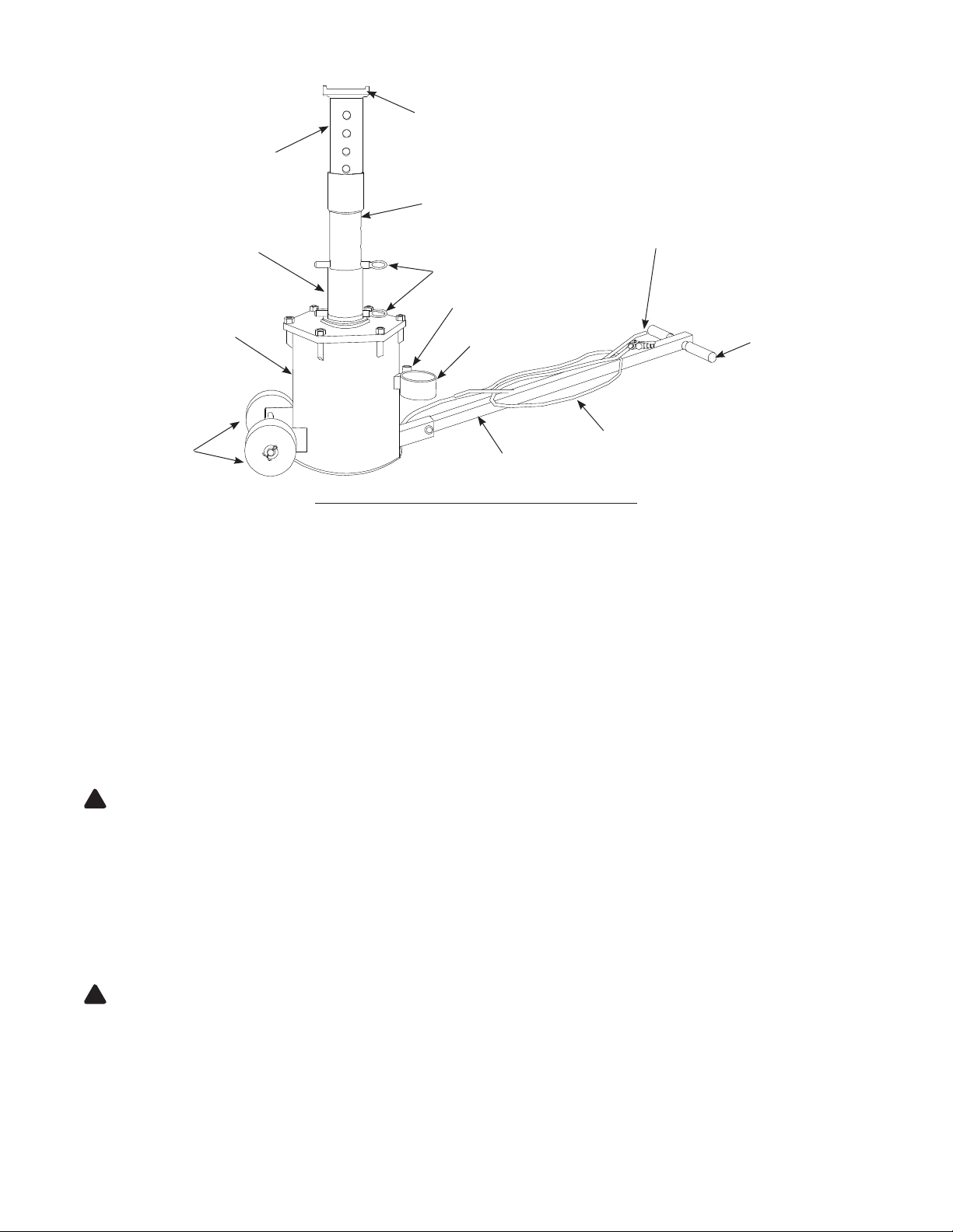
Upper Post
Saddle
Exploded Post
Low Post
Air Cylinder
Wheels
Lock Pins
Lock Pin Holder
Post Holder
Handle
Figure 1 - Air Jack/Support Stand Components
Air Control Valve
Handle Grip
Air Hose
PREPARATION
Before Use
1. Verify that the product and application are compatible, if in doubt call Atd Tools Technical Service line (636)
327-9050
2. Before use, read the operator's manual completely and familiarize yourself thoroughly with the product and its
components, and recognize the potential hazards associated with its use. Know your jack and how it operates
before attempting to use.
Assemble handle
Attached handle to the handle bracket on cylinder set with bolt and nut provided. Refer to parts drawing (page. 6)
for component location.
Prepare air system
CAUTION: Air source must not exceed 200 psi maximum.
!
1. Connect a union tting (sold separately) to the air supply inlet (ref. Fig. 2).
2. Attach 1/4" NPT coupler (sold separately) to union tting if desired.
3. Frequent, but not excessive lubrication is required for best performance. Too much oil will collect inside jack and
be expelled during exhaust cycle. An automatic inline oiler is recommended, but oil may be added manually before
operation or after approximately 1 hour of continuous use. Pour 1 teaspoon of good quality air tool lubricant into
air supply inlet of control valve.
4. Dirt and water may accumulate inside jack during use. An inline lter/dryer is recommended.
5. Air Jack/Support Stand is now ready for use.
WARNING: Never use more than one extension with this unit. Using more than one extension causes the load
!
to be lifted beyond the maximum designed safety lifting height, which could cause loss of load.
Check the jack
1. Examine the jack for broken or damaged parts. Roll the jack to ensure that it rolls freely and smoothly.
2. Raise and lower the unloaded saddle throughout the lift range to ensure proper operation before placing any load
on the product.
3. Replace worn or damaged components with factory replacement parts only. (See Replacement Parts Section).
Lubricate as instructed in Maintenance Section.
3
Page 4

Air Supply Inlet
Air Out to Jack
Valve Control
Figure 2 - Air Valve
OPERATION
Lifting
WARNING: Only attachments and/or adapters supplied by the manufacturer shall be used.
!
WARNING: Do not connect two jacks to one control valve. Operating the jacks in this way can cause of loss
!
of control during raising and lower the vehicle.
1. Follow the vehicle manufacturer’s recommended guidelines for lifting.
2. Position vehicle on hard level surface with parking brake selected. Chock wheels at opposite end. When lifting
trailers, lower landing gear.
WARNING: Do not attempt to raise a partially lled tanker or transport containing an unrestrained load. A
!
sudden load shift can occur causing dangerous tilting or toppling of the vehicle.
NOTICE: Actuation of the air control valve will raise and lower the post.
3. Position the unit under the lift point of the vehicle such that load will be centered on lifting saddle.
4. Extend post to desired height and insert locking pin through appropriate hole. If necessary, use post extension for
additional height. Post extension slides inside post and is held in place with safety pin (ref. parts drawing).
5. Connect air compressor hose to control valve, then attach to air supply of 200 psi maximum. The unit is now
ready to lift.
6. Press the air control valve lever marked "UP" to raise post until it contacts vehicle lift point. Ensure lift point is
secure and centered on lift post saddle.
7. Press and hold air control valve until desired height has been achieved, insert the other lock pin through the hole
in the ram post such that the lock pin will fully engage both sides of the head plate when lowered.
8. Slowly release the air pressure and make sure the lock pin engages fully into both sides of the low post slot.
9. Ensure the vehicle is level and stable, then fully discharge air pressure.
10. Before working around the lifted vehicle, ensure the vehicle is level and stable between the jacks.
WARNING: After lifting, never work on, under or around a load until the post is properly pinned and the air is
!
exhausted. If the air is not exhausted and the jack is not properly pinned, the jack may rise or drop suddenly
when a heavy object is removed from or placed on the vehicle.
4
Page 5

Lowering
WARNING: Check that all tools and personnel are clear before lowering load. Maintain control of speed at
!
which load descends at all times.
1. Press the "UP" air control valve lever to raise post locking pin away from cap plate.
2. Ensure the vehicle is still stable, then remove lift post locking pin.
3. Press the "DOWN" air control lever to exhaust air pressure. Vehicle will gradually lower.
4. Discharge the air pressure from the jack fully once the vehicle is on the ground.
5. Ensure saddle is fully lowered, remove jack from under the vehicle and store properly.
TROUBLESHOOTING
Symptom Possible Causes Corrective Action
• Inadequate air supply
Air Jack will not lift load
Air Jack will not hold load • Locking pin not engaged • Engage locking pin
Air Jack does not lift smoothly • Cylinder requires lubrication
• Overload condition
• Air line leaks
• Ensure adequate air supply
• Use larger capacity jack
• Locate and seal leaks
• Apply #630-AAA Lubriplate to cylinder
wall (see MAINTENANCE)
MAINTENANCE
The Air Jack/Support Stand is best operated with an in-line oiler. If using
the jack without an oiler, complete the following steps before each use, or
every hour is used continuously:
1. Disconnect the jack from the air hose.
2. Apply a few drops of good quality pneumatic tool oil through the air
line.
Inspections should be made before each use of jack, checking for abnormal
conditions. Regular inspections should be made weekly for daily use and
monthly for intermittent use.
Figure 3
1. Inspect air hose for leaks or kinks. Replace if necessary.
2. Air control valve should operate freely. Wheels should rotate freely.
3. The post should extend and retract smoothly throughout its full range. If jack does not lift smoothly, remove
bolts around cylinder cover, remove cover and lift piston weld assembly to the piston stops. Tilt the assembly to
clear the piston stops. Clean and lubricate using #630-AAA-Lubriplate.
4. A periodic coating of light lubricating oil to all rotating and sliding portions of the jack will help to prevent rust
and assure that the wheels move freely.
5. Lower the saddle to its lowest position when not in use.
6. When jack is not in use, tip it forward until it rests on the wheels and use extra support to hold the jack as
shown in Figure 3. This allows trapped water to drain from inside the cylinder.
5
Page 6

REPLACEMENT PARTS
Not all components of the jack are replacement items, but are illustrated as a convenient reference of location and
position in the assembly sequence. When ordering parts, give model number, parts number and parts description.
Replacement Parts List for ATD7350
Item Part# Description Qty.
1 34100-001 Low Post 1
2 34100-002 Gliding Ring 1
3 34100-003 Seal Ring 1
4 34100-004 Washer 1
5 34100-005 O-ring 1
6 34100-006 Bolt, M12 x 25 1
7 N/A Air Cylinder Set 1
8 34100-007 Washer 4
9 34100-008 Wheel 2
10 34100-009 Pin, 5 x 30 2
11 34100-010 Bolt, M8 x 60 1
12 34100-011 3/8" Air Hose Set 1
13 34100-012 Air Control Valve 1
14 34100-013 Handle Grip 2
15 34100-014 Washer 1
16 34100-015 Nut, M8 1
17 34100-016 Locking Pin 2
18 34100-017 Safety Pin 1
19 34100-018 Handle Assy 1
20 34100-019 Guilding Ring 1
21 N/A Cap Set 1
13
22 34100-020 Nut, M16 6
23 34100-021 Exploded Post 1
24 34100-022 Upper Post 1
Figure 4 - Parts Illustration for Model ATD7350
6
Page 7

ONE YEAR LIMITED WARRANTY
For a period of one (1) year from date of purchase, Atd Tools Inc. will repair or replace, at its option, without charge,
any of its products which fails due to a defect in material or workmanship, or which fails to conform to any implied
warranty not excluded hereby.
Performance of any obligation under this warranty may be obtained by contacting your point of sale and obtaining return
or repair information from your supplier.
Except where such limitations and exclusions are specifically prohibited by applicable law, (1) the CONSUMER'S
SOLE AND EXCLUSIVE REMEDY SHALL BE THE REPAIR OR REPLACEMENT OF DEFECTIVE PRODUCTS AS
DESCRIBED ABOVE, and (2) Atd Tools Inc. SHALL NOT BE LIABLE FOR ANY CONSEQUENTIAL OR INCIDEN-
TAL DAMAGE OR LOSS WHATSOEVER, and (3) THE DURATION OF ANY AND ALL EXPRESSED AND IMPLIED
WARRANTIES, INCLUDING WITHOUT LIMITATION, ANY WARRANTIES OF MERCHANTABILITY AND FITNESS
FOR A PARTICULAR PURPOSE, IS LIMITED TO A PERIOD OF ONE (1) YEAR FROM DATE OF PURCHASE.
Some states do not allow limitations on how long an implied warranty lasts, so the above limitation may not apply
to you. Some states do not allow the exclusion or limitation of incidental or consequential damages, so the above
limitation or exclusion may not apply to you. This warranty gives you specific legal rights, and you may also have
other rights which vary from state to state.
Atd Tools Inc.
160 Enterprise Drive, Wentzville, MO 63385
Tel: (636)327-9050 Fax: (636)327-9046 www.atdtools.com
7
 Loading...