

Page 1
OPERATING INSTRUCTIONS
MANUEL D'INSTRUCTIONS
MANUAL DE INSTRUCCIONES
3.300.849
IMPORTANT OPERATING INSTRUCTIONS
SA VE THESE INSTRUCTIONS
MODEL
ATD
37155
Page 2
2
INSTRUCTION MANU AL FOR WIRE WELDING MA CHINES
IMPORTANT:
READ THIS MANUAL CAREFULLY BEFORE
INSTALLING, USING, OR SERVICING THE WELDING
MACHINE, PAYING SPECIAL ATTENTION TO SAFETY
RULES. CONTACT YOUR DISTRIBUTOR IF YOU DO
NOT FULLY UNDERSTAND THESE INSTRUCTIONS.
1 INSTALLATION
This machine must be used for welding only.It m ust not be
used to defrost pipes.
It is also essential to pay special attention to the chapter
on SAFETY PRECAUTIONS.
The symbols next to certain paragraphs indicate points
requiring extra attention, practical advice or simple information.
This manual must be stored carefully in a place familiar to
everyone involved in using the machine. It must be consulted whenever doubts arise and be kept for the entire
life-span of the machine; it will also be used for ordering
replacement parts.
1.1 PLACEMENT
Unpack the machine and place it in an adequately ventilated area, dust-free if possible, taking care not to block
the air intake and outlet from the cooling slots.
CAUTION: REDUCED AIR CIRCULATION causes overheating and could damage internal parts.
Keep at least 500 mm of free space around the machine.
Never place any filter ing device over the air intake points
of this welding machine.
The warranty shall become void if any type of filtering
device is used.
Mount the parts supplied with the machine as shown in
the figure 1.
2 DESCRIPTION OF THE MACHINE
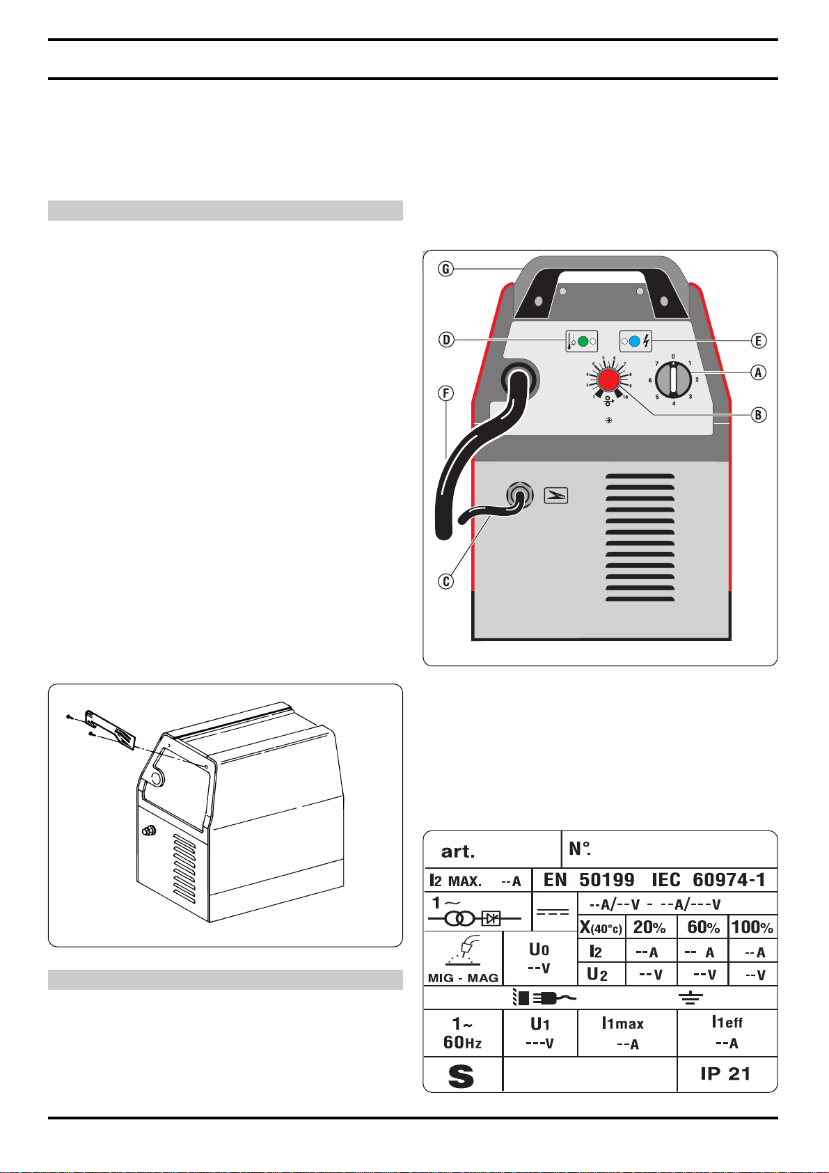
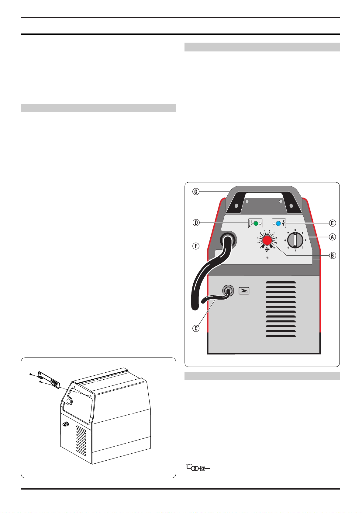
A) Switch
Turns the machine on and off, and also regulates the
welding voltage range.
B) Setting knob
This knob serves to adjust the welding wire speed.
C) Earth cable
D) Yellow LED
Lights only when the thermostat is tripped and
interrupts the machine operation.
E) Green LED
Indicates that the machine is turned on.
F) Welding torch
G) Handle
Must not be used to lift the machine.
3 GENERAL DESCRIPTIONS
3.1 SPECIFICATIONS
This welding machine allows welding of soft steel, stainless steel and aluminium.
3.2 EXPLANATION OF TECHNICAL SPECIFICATIONS
Fig. 1
Fig. 2
Page 3

3
N° Serial number which must be stated when
asking for information or servicing related to
this machine.
IEC 60974-1 The welding machine is manufactured according
EN 50199 to these international standards.
Single-phase Transformer - Rectifier
MIG/MAG. Suitable for continuous wire welding
I2 max Unconventional welding current.
The value represents the maximum level that
can be obtained in welding.
Uo Secondary no-load voltage.
X The duty-cycle expresses the percentage of
10 minutes during which the welding machine
can operate at a determined current level
without overheating: e.g. X=60% at I2=100 A.
This means that the welding machine can
weld with a current I2 = 100A for 6 minutes out
of 10, i.e. 60%.
I2 Welding current
U2 Secondary voltage with welding current I
U1 Nominal supply voltage at the rated frequency.
I1 max. This is the maximum value of the absorbed
current.
I1 eff. This is the maximum value of the actual absor-
bed current.
Ip 21 Grade of protection of the case.
Grade 1 as a second number means that this
unit is not fit for working in the rain.
S Fit for working in high-risk areas.
3.3 DESCRIPTION OF PROTECTION
This device is protected by a normally closed thermostat
on the power transformer.
When the thermostat is tripped the machine stops welding, while the motor-driven fan continues to run and the
yellow LED lights.
After it has been tripped, wait a few minutes to allow the
generator to cool down.
4 INSTALLATION
The machine must be installed by skilled personnel. All
connections must be made in compliance with current regulations and in full respect of safety laws.
Make sure that the wire diameter corresponds to the one
indicated on the roller, and mount the wire reel.Make sure
that the welding wire passes through the groove in the
small roller 7.
Before connecting the power cable 23, make sure that the
power voltage corresponds to that of the welding machine ,
then: a) for permanent connection to the power mains
without a plug, you must insert a main switch
having a suitable capacity in compliance with the
rated specifications.
b) for a plug-socket connection, use a plug having
a suitable capacity in compliance with the rated
specifications.In this case the plug must be used
to completely disconnect the machine from the
mains, after setting the switch 47 to “O” (off).
The yellow-green wire must be connected to the earth terminal.Connect the earth clamp 37 to the part to be welded.
The welding circuit must not be deliberately placed in
direct or indirect contact with the protection wire except in
the workpiece.
If the workpiece is deliberately grounded using the protection wire, the connection must be as direct as possible,
using a wire at least as large as the welding current return
wire, and connected to the workpiece at the same point as
the return wire, using the return wire clamp or a second
grounding clamp placed next to it.
All precautions must be taken to avoid stray welding currents.
Turn the machine on using the switch 47.
Remove the tapered gas tip 44 by turning it clockwise.
Unscrew the contact tip 43.
Do not press the torch trigger until you have read the
instructions carefully.
It is important to make sure the machine is turned off
whenever changing the wire reel and wire roller, to prevent
the wire feed motor from starting accidentally.
Press the torch trigger 39 and release it only when the
welding wire comes out.
Welding wire can cause puncture wounds.
Never aim the torch at parts of the body, other people or
metals when loading the welding wire.
Screw the contact tip 43 back on, making sure that the
hole diameter corresponds to the wire used.
Slide the tapered gas welding tip 44 on, always turning
clockwise.
4.1 CONNECTING THE GAS HOSE
l The gas cylinder must be equipped with a pressure
reducer and flow meter.
l If the cylinder is placed on the cylinder holder of the
machine, it must be held in place by the chain provided
and be of an appropriate size to avoid jeopardizing the
stability of the machine.
l Connect the gas hose leaving the back of the machine
to the pressure reducer only after the cylinder is in place.
l Open the gas cylinder and set the flow meter to approx-
imately 8-10 lt./min.
CAUTION:Make sure the gas used is compatible with the
material to be welded.
4.2 GENERAL NOTES
Before using this welding machine, carefully read the regulations CEI 26/9 or CENELEC HD 407 and CEI 26/11 or
CENELEC HD 433. Also make sure that the insulation on
cables, torch and earth cable is intact.
5 WELDING
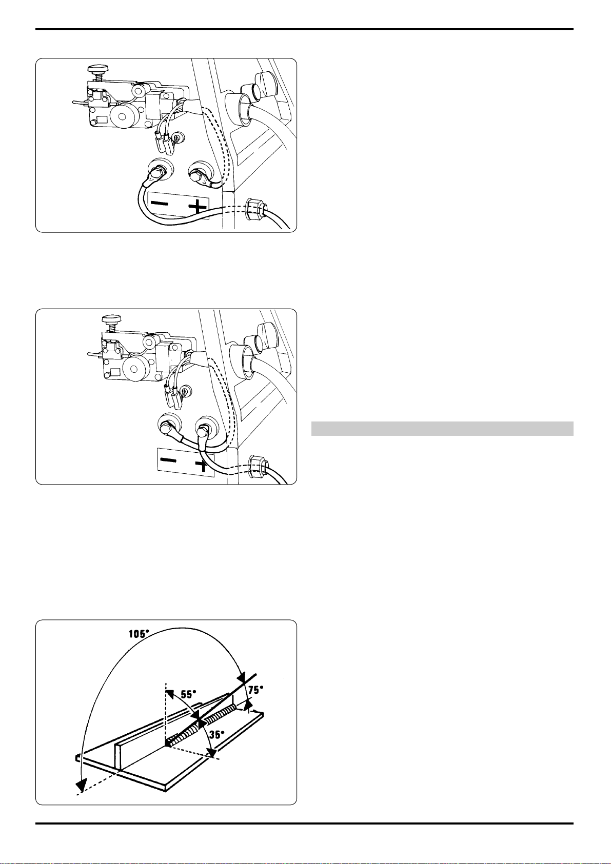
5.1 WELDING MILD STEEL
5.1.1 With gas protection.
Either 75% ARGON + 25% CO2 or 100% CO2 may be
used for welding mild steel.
Connect the cables as shown in the figure 3.
Select the welding current by means of the rotary switchl
47.
Move the torch near the welding point and press the trigger 39.
Adjust the potentiometerl knob 2 until the welding is done
with a constant, continuous noise.
If the speed is too fast, the wire tends to stick to the piece
and cause the torch to skip; if the speed is too low, the
wire melts in spaced drops or the arc does not remain lit.
Page 4
4
When you have finished w elding, turn off the machine and
close the gas cylinder.
For the correct welding angle see figure 5.
5.1.2 Without gas protection.
Connect the cables as shown in the figure 4.
Use only diam. 0.9 flux cored wire that complies with the
standard AWS AS .20 E71 TII or E71 TGS, suitab le for use
without gaseous protection.
Connect the earth cable clamp to the workpiece.
After connecting the cables, follo w the instructions given in
paragraph 5.1.1.
NOTE: For compact, well-protected welds always work
from left to right and from top to bottom.
Remove all waste after each welding operation.
For the correct welding angle see figure 5.
5.2 WELDING ALUMINIUM
The welding machine must be prepared as for welding
mild steel with gas protection, but with the following differences:
- 100% ARGON as the protection gas for welding.
- A wire having a composition suited to the base material
to be welded.
For welding ALLUMAN: 3÷5% silicon wire
- For welding ANTICORODAL: 3÷5% silicon wire
- For welding PERALUMAN: 5% magnesium wire
- For welding ERGAL: 5% magnesium wire
Use grinding wheels and brushes specifically designed for
aluminium, and never use them on other materials.
REMEMBER that cleanliness is quality!
The wire reels must be stored in nylon bags with dehumidifying packets.
For the correct welding angle see figure 5.
5.3 WELDING STAINLESS STEEL
The welding machine must be prepared as for welding
mild steel with gas protection, but with the following differences:
- Reel of stainless steel wire compatible with the composition of the material to be welded.
- Cylinder containing 98% ARGON + 2% 02 (recommended composition)
The recommended torch angle and welding direction are
shown in figure 5.
6 MAINTENANCE AND CHECKS
6.1 GENERAL NOTES
l Turn off the welding machine and unplug the power cord
from the socket before each checking and maintenance
operation.
l Moving parts can cause serious lesions
l Keep away from moving parts.
l INCANDESCENT SURFA CES can cause serious burns.
l Let the unit cool before servicing.
l Periodically remove any dust or foreign matter that may
have deposited on the transf ormer or diodes;to do so, use
a jet of clean, dry air.
l When replacing the wire roller, make sure the groove is
aligned with the wire and corresponds to the diameter of
the wire used.
l Always keep the interior of the gas nozzle clean to avoid
metal bridges created by welding dross between the gas
nozzle and the contact tip.Make sure the outlet hole of the
contact tip has not expanded excessively; if so, replace.
l Strictly avoid striking the torch or allowing it to suffer vio-
lent impact.
6.2 REPAIRING THE WELDING MACHINE
Experience has shown that many accidents are caused by
repairs performed incorrectly. That is why it is just as
important to check a repaired welding machine carefully
and completely as it is for a new welding machine.
In addition, this protects the manufacturer from being held
liable for defects when the true fault lies elsewhere.
Fig. 5
Fig. 3
Fig. 4
Page 5
5
6.2.1 Instructions for performing repairs
l After rewinding the transformer or inductance, the weld-
ing machine must pass the applied voltage tests as indicated in table 2 of paragraph 6.1.3 of the standard EN
60974.1 (CEI 26.13). Compliance must be verified as
specified in 6.1.3.
l If no rewinding has been done, a welding machine that
has been cleaned and/or revised must pass an applied
voltage test with test voltage values equal to 50% of the
values given in table 2 of paragraph 6.1.3. Compliance
must be verified as specified in 6.1.3.
l After rewinding and/or replacing parts, the no-load volt-
age must not exceed the values given in paragraph 10.1
of EN 60974.1.
l If the repairs have not been performed by the manufac-
turer, repaired welding machines in which some components have been replaced or altered must be marked in
such a way that the person who perfor med the repairs is
clearly identifiable.
l After making repairs, take care to re-order the wiring so
that there is certain insulation between the primar y side
and the secondary side of the machine. Prevent the wires
from coming into contact with moving parts or parts that
heat up during operation. Replace all clamps as on the
original machine to prevent a connection from occurring
between the primary and secondary side if a conductor
accidentally breaks or disconnects.
6.3 TROUBLESHOOTING GUIDE
7 SAFETY PRECAUTIONS
7.1 FIRE
l Avoid causing fire because of sparks,
slag, hot metal or pieces.
l Make sure that suitable fire-fighting equip-
ment is available close to welding area.
l Remove all flammable and combustible material from
the welding area and its surrounding (32 ft minimum).
l Do not weld containers of combustible or flammable
material, even when empty. These must be carefully
cleaned before being welded.
l Allow the welded material to cool down before touching it or
putting it in contact with combustible or flammable material.
l Do not weld parts with hollow spaces, containing flam-
mables.
l Do not work under conditions with high concentrations of
combustible vapours, gases, or flammable dust.
l Always check the work area half an hour after welding
so as to make sure that no fire has started.
l Do not keep any combustible material such as lighters or
matches in your pockets.
7.2 BURNS
l Wear fire-proof clothing all over your body in order to pro-
tect your skin against burns caused by ultraviolet radiation
given off by the arc, and from weld metal spar ks and slag.
l Wear protective clothing-gauntlet gloves designed for
use in welding, hat and high safety-toe shoes.Button shirt
collar and pocket flaps, and wear cuff-less trousers to
avoid entry of sparks and slag.
l Wear helmet with safety goggles and glasses with side
shields underneath, appropriate filter lenses or plates (protected by clear cover glass).This is a MUST for welding to
protect the eyes from radiant energy and flying metal.
Replace cover glass when broken, pitted, or spattered.
l Avoid oil or greasy clothing. A spark may ignite them.
Hot metal such as electrode stubs and workpieces should
never be handled without gloves.
l First-aid facilities and a qualified first-aid person should
be available for each shift unless medical facilities are
close by for immediate treatment of flash b urns of the eyes
and skin burns.
l Ear plugs should be worn when working on overhead or
in a confined space.A hard hat should be worn when others work overhead.
l Flammable hair preparations should not be used by per-
sons intending to weld or cut.
7.3 FUMES
Welding operations give off harmful fumes and
metal dusts which may be hazardous to your
health, therefore:
l Work in a well-ventilated area.
l Keep your head out of fumes.
l In closed areas, use suitable exhaust fans.
l If ventilation is not enough, use breathing sets approved
for this procedure.
l Clean the material to be welded of any solvents or halo-
gen degreasers giving rise to toxic gases. Some clorine
solvents may decompose with the radiation emitted by the
arc, and create phosgene gas.
l Do not weld plated metals or those containing lead,
ROUBLE
The welding machine supplies limited
current
Welding with a lot
of metal spatter
The wire jams or
entangles between
the drive rolls and
the torch infeed wire
guide
No wire feed or irregular wire feed
Porosity in the welding seam
PROBABLE CAUSE
Line fuse blown
Burnt out diode or diodes
Burnt out electronic board
Loosened torch or earth
connections or any other
electrical power connections
Voltage adjustment switch
has a loose contact
Improper adjustment of
welding parameters
Insufficient grounding
Contact tip with wrong diameter
Misalignment of the drive
roll groove
Obstructed or clogged
liner
Drive roll with too large a
groove
Obstructed or clogged
liner
Wire holding roller not
completely tightened
Clogged contact tip
Insufficient shielding gas
Excess oxidation of the
edges to be welded
Gas nozzle partially or
completely clogged by
spatter
REMEDY
Replace line fuse
Replace
Replace
Tighten all connections
Replace the switch
Select the correct parameters through the weldingvoltage switch and the
wire-speed adjustment
potentiometer
Check grounding connections
Replace
Realign
Remove and clean
Replace the drive roll
Remove and clean
Tighten all the way
Replace
Increase gas delivery
Thoroughly clean the
edges with a metal brush
Remove and clean or
replace being careful not
to clog the gas outlets
Page 6
6
graphite, cadmium, zink, chrome, mercury or beryllium,
unless you have the proper breathing set.
l The electric arc creates ozone. A long exposure to high
concentrations may cause headaches, nasal, throat and
eye irritation as well as serious congestions and chest
pains.
IMPORTANT: DO NOT USE OXYGEN FOR VENTILATION.
l Gas leaks in a confined space should be avoided.
Leaked gas in large quantities can change oxygen concentration dangerously. Do not bring gas cylinders into a
confined space.
l DO NOT WELD where solvent vapors can be drawn into
the welding atmosphere or where the radiant energy can
penetrate to atmospheres containing even minute
amounts of trichloroethylene or perchloroethylene.
7.4 EXPLOSIONS
Do not weld above or near containers under pressure.
l Do not weld in environments containing explo-
sive dusts, gases or vapours.
This welding machine uses inert gases such as CO2,
ARGON, or a mixture of ARGON + CO2 for the protection
of the arc, thus you should take special precautions:
A) CYLINDERS
l Do not directly connect cylinder to the machine gas hose
without a pressure regulator.
l Handle or use pressure cylinders in conformity with the
existing rules.
l Do not use leaking or damaged cylinders.
l Do not use cylinders which are not well secured.
l Do not carry cylinders without the protection of the
installed valve.
l Do not use cylinders whose content has not been clear-
ly identified.
l Never lubricate cylinder valves with oil or grease.
l Do not put the cylinder in electrical contact with the arc.
l Do not expose cylinders to excessive heat, sparks,
molten slags or flame.
l Do not tamper with the cylinder valves.
l Do not try to loosen tight valves by means of hammers,
keys, or any other object.
l NEVER DEFACE or alter name, number, or other mark-
ings on a cylinder.It is illegal and hazardous.
l Do not lift cylinders off the ground by their valves or
caps, or by chains, slings or magnets.
l Never tr y to mix any gases in a cylinder.
l Never refill any cylinder.
l Cylinder fittings should never be modified or exchanged.
B) PRESSURE REGULATORS
l Keep pressure regulators in good condition. Damaged
regulators may cause damages or accidents, they should
only be repaired by skilled personnel.
l Do not use regulators for gases other than those for
which they are manufactured.
l Never use a leaking or damaged regulator.
l Never lubricate regulators with oil or grease.
C) HOSES
l Replace hoses which appear damaged.
l Keep hoses unwound in order to avoid bending.
l Keep the excess hose wound and out of the working
area in order to avoid any damage.
7.5 RADIATIONS
Ultra-violet radiation created by the arc may damage your eyes and bur n your skin. Therefore:
l Wear proper clothing and helmet.
l Do not use contact lenses!! The intense heat coming
from the arc may cause them to stick to the cornea.
l Use masks with grade DIN 10 or DIN 11 safety lenses at
the least.
l Protect people in the surrounding welding area.
Remember: the arc may dazzle or damage the eyes. It is
considered dangerous up to a distance of 15 meters (50
feet). Never look at the arc with the naked eye.
l Prepare the welding area so as to reduce reflection and
transmission of ultra-violet radiation. Paint walls and
exposed surfaces in black to reduce reflection, install
sheathings or curtains to reduce ultra-violet transmissions.
l Replace mask lenses whenever damaged or broken.
7.6 ELECTRIC SHOCK
Electric shock can kill.
All electric shocks are potentially fatal.
l Do not touch live parts.
l Insulate yourself from the piece to be cut and from the
ground by wearing insulated gloves and clothing.
l Keep gar ments (gloves, shoes, hats, clothing) and body
dry.
l Do not work in humid or wet areas.
l Avoid touching the piece to be welded.
l Should you work close to or in a dangerous area, use all
possible precautions.
l If you should feel even the slightest electric shock sen-
sation, stop welding immediately. Do not use the machine
until the problem is identified and solved.
l Always fit an automatic wall switch with adequate po wer,
possibly close to the machine, allowing you to immediately switch the machine off in case of an emergency.
l Frequently inspect the power supply cable.
l Disconnect power supply cable from mains before
replacing cables or before removing unit covers.
l Do not use the unit without protection covers.
l Always replace any damaged parts of the unit, with orig-
inal material.
l Never disconnect unit safety devices.
l Make sure that the power supply line is equipped with an
efficient earth plug.
l Make sure that the work bench and the workpiece are
connected to an efficient earth plug.
l Any maintenance should only be carried out by qualified
personnel aware of the risks due to dangerous voltages
necessary for the operation of the unit.
7.7 PACE MAKER
l Magnetic fields from high currents can affect pacemak-
er operation. Persons wearing electronic life support
equipment (pacemaker) should consult their doctor before
going near arc welding, gouging or spot welding operations.
7.8 CAUTION! WELDING WIRE CAN CAUSE PUNCTU
Page 7
7
RE WOUNDS.
l Do not press gun trigger until instructed to do so.
l Do not point gun toward any part of the body, other peo-
ple, or any metal when threading welding wire.
7.9. MOVING PARTS CAN CAUSE INJURY.
Moving parts, such as fans, can cut fingers and hands and
catch loose clothing.
l Keep all doors, panels, covers, and guards closed and
securely in place.
l Have only qualified people remove guards or covers for
maintenance and troubleshooting as necessary.
l Keep hands, hair, loose clothing, and tools away from
moving parts.
l Reinstall panels or guards and close doors when ser-
vicing is finished and before starting the machine.
7.10 NOISE
These power source alone do not produce noise
levels exceeding 80 dB. The welding procedure,
however, may produce noise levels in excess of
80 dB. in which case the machine operator must take the
necessary safety precautions as prescribed by the national safety regulation.
Page 8
8
2 DESCRIPTION DE LA MACHINE
A) Interrupteur.
Il sert pour mettre en marche ou arrêter la machine
ainsi que pour régler les valeurs de la tension de soudure.
B) Bouton de réglage.
A l’aide de ce bouton, il est possible de régler la vites-
se du fil de soudure.
C) Câble de masse.
D) Led jaune.
Elle s’allume uniquement lorsque le thermostat inter-
rompt le fonctionnement du poste à souder.
E) Led verte.
Elle indique la mise en marche de la machine.
F) Torche de soudure.
G) Poignée.
Elle ne doit pas être utilisée pour le levage.
3. DESCRIPTIONS GENERALES
3.1 SPECIFICATIONS
Ce poste à souder permet la soudure d’acier doux, acier
inoxydable et aluminium.
3.2. EXPLICATION DES DONNEES TECHNIQUES
N° Numéro de matricule qui doit toujours être
indiqué pour toute demande relative à ce
poste à souder.
IEC 60974-1 Le poste à souder est constr uit selon ces
EN 50199 normes internationales
Transformateur - Redresseur monophasé
MIG/MAG. Indiqué pour la soudure à fil continu.
IMPORTANT:
A VANT D’INSTALLER, EMPLO YER, OU BIEN COMMENCER TOUT ENTRETIEN AU POSTE A SOUDER, IL
FAUT LIRE LE CONTENU DE CE MANUEL EN FAISANT
PARTICULIERE ATTENTION AUX NORMES DE SECURITE. CONTACTEZ VOTRE DISTRIBUTEUR SI VOUS
N’AVEZ PAS COMPLETEMENT COMPRIS CES
INSTRUCTIONS.
1. INTRODUCTION
Cette machine ne doit être employée que pour des opérations de soudure et ne doit pas être utilisée pour décongeler les tuyaux.Il est cependant indispensab le de donner
toute l’attention possible au chapitre concernant les PRECAUTIONS DE SECURITE.
Les symboles placés à proximité des paragraphes auxquels se réfèrent ont le but de mettre en évidence des
situations d’attention maximum, des conseils pratiques ou
bien quelques simples renseignements.
Ce manuel doit être gardé avec soin, dans un lieu connu
par les différentes personnes intéressées. Il devra être
consulté chaque fois qu’on a des doutes;il devra suivre la
vie opérationnelle de la machine et sera utilisé pour émettre les commandes d’achat des pièces de rechange.
1.1 MISE EN PLACE
Enlever la machine de son emballage et la placer dans un
endroit ayant une ventilation appropriée, si possible sans
poussières, en faisant attention à ne pas obturer l’entrée
et la sortie de l’air dans les grilles de refroidissement.
ATTENTION: UNE CIRCULATION REDUITE DE L’AIR
cause la surchauffe et de possibles endommagements
des parties intérieures.
Laisser au moins 500 mm d’espace libre tout autour de la
machine.
Ne placer aucun dispositif de filtration sur les passages
d’entrée de l’air de ce poste à souder.
La garantie devient nulle lorsqu’on utilise un dispositif de
filtration de n’importe quel type.
Monter les pièces fournies avec la machine comme indiqué en figure 1.
MANUEL D’INSTRUCTIONS POUR POSTES A SOUDER A FIL
Fig. 1
Fig. 2
Page 9

9
la tension de réseau correspond à celle du poste à souder.
En suite:a) En cas de branchement permanent au
système d’alimentation sans fiche, il faut prév oir
un interrupteur général de capacité adéquate
par rapport aux données de la plaque.
b) En cas de branchement avec fiche, utiliser
une fiche de capacité adéquate par rapport aux
données de la plaque.Dans ce cas la fiche doit
être utilisée pour débrancher complètement la
machine du réseau, après avoir positionné
l’interrupteur 47 sur «O».
Le conducteur vert/jaune doit être raccordé à la borne de
terre. Raccorder la borne du câble de masse 37 à la pièce
à souder.
Le circuit de soudure ne doit pas être placé délibérément au
contact direct ou indirect avec le conducteur de protection,
sauf dans la pièce à souder.
Si la pièce à usiner est raccordée délibérément à la terre à
travers le conducteur de protection, le raccordement doit
être le plus direct possible et exécuté au moyen d’un conducteur de section au moins égale à celle du conducteur de
retour du courant de soudure et raccordé à la pièce à usiner en utilisant la borne du conducteur de retour ou bien
une deuxième borne de masse placée immédiatement à
proximité.Toute précaution possible doit être prise afin
d’éviter des courants errants de soudure.
Mettre la machine en marche à l’aide de l’interrupteur 47.
Extraire la buse gaz conique 44 en la tournant en sens
horaire.Dévisser la buse porte-courant 43.
Ne pas appuyer sur le bouton de la torche av ant d’av oir
lu soigneusement le mode d’emploi.
Il est important de s’assurer que la machine est arrêtée
chaque fois qu’on remplace la bobine du fil et le rouleau
entraîne-fil afin d’éviter que le motoréducteur démarre accidentellement.
Appuyer sur le bouton de la torche 39 et le laisser uniquement à la sortie du fil.
Le fil de soudure peut causer des blessures perforées.
Ne pas pointer la torche vers des parties du corps, d’autres
gens ou biens des métaux lors du montage du fil de soudure.
Revisser la buse porte-courant 43 en s’assurant que le
diamètre du trou est égal au fil employé.
Introduire la buse gaz conique de soudure 44 en la tournant
toujours en sens horaire.
4.1 RACCORDEMENT DU TUYAU DU GAZ
l La bouteille de gaz doit être équipée d’un détendeur de
pression et d’un débitmètre.
l Si la bouteille est positionnée sur la plate-forme de la
machine, elle doit être fixée à l’aide de la chaîne prévue et
avoir des dimensions telles à ne pas compromettre la stabilité de la machine.
l Positionner tout d’abord la bouteille et en suite exécuter le
raccordement du tuyau du gaz sortant de la partie arrière
de la machine au détendeur de pression.
l Ouvr ir la bouteille de gaz et régler le débitmètre à 8/10
litres/min. environ.
ATTENTION: Contrôler que le gaz employé est compatible
avec le matériel à souder.
I2 max Courant de soudure non conventionnel.
Le valeur représent la limite maximale pouvant
être obtenue en soudure.
Uo Tension à vide secondaire.
X Le facteur de marche exprime le pourcentage
de 10 minutes au cours desquelles le poste à
souder peut travailler avec un courant fixé
sans provoquer des surchauffages.
Par exemple: X = 60% a I2 = 100 A.
Cela signifie que le poste à souder peut
souder avec un courant I2 = 100A pendant 6
minutes sur 10, c’est-à-dire 60%.
I2 Courant de soudage.
U2 T ension secondaire a vec cour ant de soudage I2.
U1 Tension nominale d’alimentation à la fréquence
décrite.
I1 max. C'est la valeur maximale du courant absorbé.
I1 eff. C'est la valeur maximale du courant
effectif absorbé.
IP21 Degré de protection de la carcasse.
Degré 1 comme deuxième chiffre signifie que
cet appareil ne peut pas être utilisé
sous la pluie.
S Indiqué pour travailler dans des locaux
soumis à un risque accru.
3.3. DESCRIPTION DE LA PROTECTION
Cette machine est protégée par un thermostat normalement fermé positionné sur le transformateur de puissance.
Lors de l’entrée en fonction du thermostat, la machine
cesse de souder tandis que le ventilateur à moteur continue
à fonctionner et la led jaune s’allume.
Après l’entrée en fonction, attendre quelques minutes de
façon à permettre le refroidissement du générateur.
4 MISE EN OEUVRE
L’installation de la machine doit être exécutée par personnel
expert.Tous les raccordements doivent être exécutés selon
les normes en vigueur et dans le respect total de la réglementation en matière de prévention des accidents.
Contrôler que le diamètre du fil correspond au diamètre
indiqué sur le rouleau et monter la bobine du fil. S’assurer
que le fil de soudure passe à l’intérieur de la gorge du rouleau 7.
Avant de r accorder le cordon d’alimentation 23, s’assurer que
Page 10

10
avec la norme AWS AS.20 E71 TII ou bien E71 TGS, apte
à l’emploi sans protection de gaz.
Raccorder la pince du câble de masse à la pièce à souder.
Après avoir raccordé les câbles suivre les mêmes instructions décrites au paragraphe 5.1.1.
N.B. Afin d’obtenir des soudures raccordées et bien
protégées, procéder toujours de gauche à droite et du haut
vers le bas.
A la fin de chaque soudure, enlever les déchets.
Pour la correcte inclinaison de soudure, voir figure 5.
5.2 SOUDURE DE L’ALUMINIUM
Le poste à souder doit être prédisposé comme pour la soudure de l’acier doux avec protection de gaz, en appliquant
les variations suivantes:
- ARGON 100 % en tant que gaz de protection pour la soudure.
- Un fil d’apport de composition adéquate au matériel
de base à souder.
- Pour souder ALUMAN fil 35 % silicium.
- Pour souder ANTICORODAL fil 35 % silicium.
- Pour souder PERALUMAN fil 5% magnésium.
- Pour souder ERGAL fil 5 % magnésium.
Utiliser des meules et des brosseuses spécifiques pour l’aluminium sans jamais les utiliser sur d’autres matériels.
SE RAPPELER que propreté veut dire qualité!
Les bobines de fil doivent être gardées à l’intérieur de
sachets en nylon avec un déshumidificateur.
Pour la correcte inclinaison de soudure, voir figure 5.
5.3 SOUDURE DE L’ACIER INOXYDABLE
Le poste à souder doit être prédisposé comme pour la soudure de l’acier doux avec protection de gaz, en appliquant
les variations suivantes:
- Bobine de fil d’acier inoxydable compatible avec la composition de l’acier à souder.
- Bouteille contenant de l’ARGON 98 % + O2 2% (composition conseillée).
L’inclinaison de la torche et la direction de soudure conseillées sont illustrées dans la figure 5.
6 ENTRETIEN ET CONTROLES
L’entretien doit être exécuté par personnel qualifié.
4.2 NOTES GENERALES
Avant d’utiliser ce poste à souder, lire soigneusement les
normes CEI 26/9 ou bien CENELEC HD 407 et CEI 26/11
ou bien CENELEC HD 433.En outre vérifier l’intégrité de l’isolement des câbles, de la torche et du câble masse.
5 SOUDURE
5.1 SOUDURE DE L’ACIER DOUX.
5.1.1 Avec protection de gaz.
Pour les soudures d’acier doux on peut utiliser de l’ARGON
75% + CO2 25% ou bien CO2 100%.
Raccorder les câbles comme d’après la figure 3.
Choisir la tension de soudure au moyen du bouton du commutateur rotatif 47.
Se rapprocher au point de soudure et appuyer sur le bouton de la torche 39.
Tourner le bouton du potentiomètre 2 jusqu’à obtenir une
soudure avec un bruit constant et continu.
Avec une vitesse trop élevée le fil tend à trébucher en faisant rebondir la torche; avec une vitesse trop réduite le fil
fond à gouttes irrégulières ou bien l’arc ne demeure pas
allumé.
Après avoir exécuté la soudure, arrêter la machine et fermer la bouteille de gaz.
Pour la correcte inclinaison de soudure, voir figure 5.
5.1.2 Sans protection de gaz.
Raccorder les câbles comme d’après la figure 4.
On ne doit utiliser que du fil avec âme 0,9 en confor mité
Fig. 4
Fig. 5
Fig. 3
Page 11

11
6.1 NOTES GENERALES
l Arrêter le poste à souder et retirer la fiche d’alimentation
de la prise avant d’effectuer toute opération de contrôle et
entretien.
l Les parties en mouvement peuvent causer des lésions
graves.
l Se tenir éloigné des parties en mouvement.
LES SURFACES INCANDESCENTES peuvent causer des
brûlures graves.
l Laisser refroidir avant de procéder a l’entretien.
l Enlever périodiquement la poussière ou les matières
étrangères qui se sont déposées éventuellement sur le
transformateur ou sur les diodes;pour ce faire utiliser un jet
d’air sec et propre.
l Lors du remontage du rouleau entraîne-fil, veiller à ce que
la gorge soit alignée au fil et que corresponde au diamètre
du fil employé.
l Maintenir toujours propre l’intérieur de la buse du gaz de
façon à éviter des ponts métalliques constitués de jets de
soudure entre la buse du gaz et la buse porte-courant.
S’assurer que le trou de sortie de la buse porte-courant ne
s’est pas trop élargi; dans le cas contraire procéder à son
remplacement.
l Eviter absolument de frapper la torche ou de lui provoquer
des chocs violents.
6.2 DEPANNAGES DES POSTES A SOUDER
L’expérience a montré que beaucoup d’accidents mor tels
sont causés par des dépannages non exécutés selon les
règles de l’art. C’est pour cette raison qu’un contrôle complet et soigné sur un poste à souder dépanné est autant
important que le contrôle sur un poste à souder neuf.
De cette manière les producteurs sont également protégés
de l’accusation d’être responsables de défauts lorsque la
faute est à imputer à d’autres.
6.2.1 Prescriptions à suivre pour les dépannages
l Après le réenroulement du transformateur ou des induc-
tances, le poste à souder doit passer les essais de tension
appliquée comme d’après le tableau 2 de 6.1.3. de la
norme EN 60974.1 (CEI 26.13).La conformité doit être vérifiée comme spécifié au point 6.1.3.
l Si aucun réenroulement n’a été effectué, un poste à soud-
er nettoyé et/ou révisé doit passer un essai de tension
appliquée avec les v aleurs de la tension d’essai à 50 % des
valeurs données dans le tableau 2 de 6.1.3. La conformité
doit être vérifiée comme spécifié au point 6.1.3.
l Après le réenroulement et/ou le remplacement de pièces,
la tension à vide ne doit pas dépasser les valeurs exposées
au point 10.1 de EN 60974.1.
l Si les dépannages ne sont pas exécutés par le produc-
teur, les postes à souder où on a remplacé ou modifié
quelques composants doivent être marqués de façon à
identifier l’auteur du dépannage.
l Après l’exécution d’un dépannage, veiller à ranger le
câblage de façon à avoir un isolement sûr entre le côté primaire et le côté secondaire de la machine.
l Eviter que les fils puissent venir en contact avec les par-
ties en mouvement ou les parties se chauffant pendant le
fonctionnement. Remonter tous les colliers comme sur la
machine d’origine de façon à éviter que, si par hasard un
conducteur se casse ou se débranche, se puisse vérifier un
raccordement entre le primaire et le secondaire.
6.3 PANNES D’EMPLOI
7 PRECAUTIONS GENERALES.
7.1 Feu.
l Eviter que le feu ne se déclare par suite
d’étincelles et de scories chaudes ou de
corps incandescents.
l S’assurer que des dispositifs appropriés contre l’incen-
die soient disponibles près de la zone de soudage.
l Enlever de la zone de soudure et de la zone environ-
nante (10 mètres au moins) les matériaux inflammables et
les combustibles.
l Ne pas effectuer de soudure sur les récipients de com-
bustible et de lubrifiant, même s’ils sont vides. Ces récipients doivent être attentivement nettoyés avant d’être
soudés.
l Laisser refroidir le matériau soudé avant de le toucher
ou de le mettre en contact avec des matériaux combusti-
INCONVENIENT
Le débit de courant
est limité
Soudage avec plusieurs giclées de
métal
Le fil n’avance pas
ou avance irrégulièrement
Le fil se bloque et
s’entortille entre les
rouleaux et le guidefil d’entrée dans la
torche
Porosité dans le
cordon de soudure
CAUSE PROBABLE
Le fusible de la ligne est
grillé
Diode ou diodes grillées
Circuit de contrôle grillé
Connexions de la torche ou
de la masse ou toute autre
connexion desserrées
Le contact au commutateur de régulation du courant de soudage est faible
Réglage erroné des
paramètres de soudage
Connexions de masse
insuffisantes
Rouleau d’entraînement
du fil doté d’une gorge
trop large
Gaine obstruée ou bouchée
Rouleau presse-fil non
serré à fond
Friction du porte-bobine
trop serré
Buse gaz obstruée
Buse gaz d’un diamètre
erroné
La gorge du rouleau n’est
pas correctement alignée
La canette n’est pas en
position
Gaine obstruée ou bouchée
Insuffisance du gaz de
protection
Bords à souder excessivement oxydés
Buse gaz partiellement ou
totalement obstruée par
les glicées
REMEDE
Remplacer le fusible.
Remplacer
Remplacer
Serrer toutes les
conexions
Remplacer le commutateur
Rechercher les paramètres
exacts en agissant sur le
po- tentiomètre de la tension de soudage et sur le
potentio- mètre de la vitesse du fil
Contrôler l’efficacité des
connexions
Remplacer le rouleau
L’extraire et la nettoyer
Le serrer à fond
Desserrerle en agissant
sur le réglage
La remplacer
La remplacer
L’aligner
L’approcher le plus possible
du rouleau qui entraîne le fil
L’extraire et la nettoyer
Augmenter le débit de gaz
Nettoyer soigneusement
avec une brosse métallique
les bords à souder
La démonter et la nettoyer
ou bien la remplacer en
ayant soin de ne pas
obstruer les orifices de
sortie des gaz
Page 12

12
bles ou inflammables.
l Ne pas effectuer de soudure sur des pièces qui possè-
dent des insterstices pouvant contenir des matériaux
inflammables.
l Ne pas travailler dans un milieu contenant des concen-
trations élevées de vapeurs combustibles, des gaz ou des
poussières inflammables.
l Contrôler toujours la zone de travail une demi-heure
après la soudure pour s’assurer qu’il n’y ait pas un début
d’incendie.
l Ne pas garder dans les poches des matériaux combu-
stibles comme des briquets ou des allumettes.
7.2 Brûlures.
l Pour protéger la peau contre les brûlures provoquées
par les radiations ultraviolettes émises par l’arc, contre les
étincelles et les scories de métal fondu, utiliser des vêtements ignifuges qui recouvrent toutes les parties exposées du corps.
l Revêtir des vêtements/gants utilisés par les soudeurs,
une casquette et des bottillons avec la pointe de sécurité.
Boutonner le col de la chemise et les pattes des poches
et utiliser des pantalons sans revers pour éviter que les
étincelles et les scories ne pénètrent dans ces revers.
l Mettre un casque avec une vitre de protection à l’extérieur
et des verres filtrants à l’intérieur. Il s’agit d’une précaution
IMPERATIVE pour les opérations de soudage pour protéger
les yeux des radiations et des métaux volatils. Remplacer la
vitre de protection si cassée, grêlée ou tachetée.
l Eviter les vêtements graisseux ou sales de graisse. Une
étincelle pourrait les enflammer.
l Utiliser toujours des gants pour saisir les parties métal-
liques incandescentes, telles que des morceaux d’électrode ou des pièces à usiner.
l Des instruments pour une urgence et une personne
qualifiée devraient toujours être disponibles pour chaque
brigade de travail à moins que des structures sanitaires ne
se trouvent dans les environs pour un traitement immédiat
et éventuel de brûlures aux yeux, dérivant de flambées,
ou de brûlures de la peau.
l Des bouchons pour les oreilles devraient être utilisés lor-
squ’on travaille au plafond ou dans un espace réduit. Un
bonnet solide doit être coiffé lorsque d’autres personnes
travaillent dans la zone située au dessus.
l Les personnes qui doivent souder ou découper ne doivent
pas utiliser des produits inflammables pour les cheveux.
7.3 Fumées.
Les opérations de soudage produisent des
fumées et des poussières métalliques nocives à
la santé. Il faut donc:
l Trav ailler dans des locaux munis d’une v entilation appro-
priée.
l Garder la tête hors des fumées.
l Utiliser, dans des locaux fermés, des aspirateurs appro-
priés.
l Utiliser des respirateurs agréés si la ventilation n’est pas
adéquate.
l Nettoyer le matériau à souder si l’on note la présence de
solvants ou de dégraissants halogènes qui donnent origine à des gaz toxiques. Durant le soudage quelques solvants chlorinés peuvent se décomposer en présence de
radiations émises par l’arc et engendrer des gaz phosgènes.
l Ne pas souder des métaux recouverts ou contenant du
plomb, de la graphite , du cadmium, du zinc, du chrome, du
mercure ou du béryllium si l’on ne dispose pas d’un respirateur approprié.
l L’arc électrique produit de l’ozone. Une exposition pro-
longée dans des milieux avec de hautes concentrations
d’ozone peut provoquer des maux de tête , de l’irritation au
nez, à la gorge et aux yeux, de graves congestions et des
douleurs de poitrine.
IMPORTANT: NE PAS UTILISER DE L’OXYGENE POUR
LA VENTILATION.
l Eviter des pertes de gaz dans des espaces réduits.Des
pertes de gaz impor tantes peuvent modifier, de manière
dangereuse, la concentration d’oxygène .Ne jamais placer
des bouteilles de gaz dans des espaces réduits.
NE JAMAIS SOUDER ou découper dans les locaux où
des vapeurs de solvant peuvent être mêlées à l’atmosphère de soudage ou de découpe ou bien lorsque l’énergie radiante peut pénétrer dans des atmosphères qui
contiennent du trichloréthylène ou du perchloréthylène.
7.4 Explosions.
l Ne pas effectuer des soudures au dessus ou à
proximité de récipients sous pression.
l Ne pas souder dans un milieu contenant des
poussières, gaz ou vapeurs explosifs.
l Ce poste à souder utilise des gaz inertes comme le
CO2, l’ARGON ou des mélanges de ARGON + C02 pour
la protection de l’arc; il faut donc faire très attention a:
A) BOUTEILLES.
l Ne jamais relier directement la bouteille au tube de gaz
de l’appareil sans utiliser un régulateur de pression.
l Manipuler ou utiliser des bouteilles sous pression
conformément aux normes en vigueur.
l Ne pas utiliser des bouteilles qui perdent ou qui sont
physiquement endommagées.
l Ne pas utiliser des bouteilles qui ne soient pas bien
fixées.
l Ne pas transporter des bouteilles sans la protection de
la soupape montée.
l Ne jamais utiliser des bouteilles dont le contenu n’a pas
été clairement identifié.
l Ne jamais lubrifier les soupapes de la bouteille avec de
l’huile ou de la graisse.
l Ne jamais mettre en contact électrique la bouteille avec
l’arc.
l Ne jamais exposer les bouteilles à une chaleur excessiv e,
à des étincelles, à des scories fondues ou à des flammes.
l Ne jamais agir sur les soupapes de la bouteille.
l Ne pas essayer de débloquer avec des mar teaux, des
clés ou autres systèmes les soupapes bloquées.
l NE JAMAIS EFFACER et ne jamais modifier le nom, le
numéro ou autres marques figurant sur la bouteille. Cela
est illégal et dangereux.
l Ne jamais soulever les bouteilles du sol en les prenant
par la valve ou par le bouchon ou en utilisant des chaînes,
des élingues ou des aimants.
l Ne jamais essayer de mélanger des gaz à l’intérieur de
la bouteille.
l Ne jamais recharger les bouteilles.
l Ne jamais modifier ou changer les raccords des bouteilles.
B) REGULATEURS DE PRESSION.
Page 13

13
l Maintenir les régulateurs de pression en parfait état.Des
régulateurs endommagés peuvent provoquer des
inconvénients ou causer des accidents. Ils doivent être
réparés uniquement par un personnel qualifié.
l Ne pas utiliser des régulateurs pour des gaz différents
de ceux pour lesquels ils ont été fabriqués.
l Ne jamais utiliser un régulateur qui perd ou qui apparaît
physiquement endommagé.
l Ne jamais lubrifier un régulateur avec de l’huile ou de la
graisse.
C) TUBES.
l Remplacer les tubes qui semblent détériorés.
l Tendre les tubes pour éviter les plis.
l Enrouler le tube excédent et le garder hors de la zone
de travail pour éviter des endommagements éventuels.
7.5 Radiations.
Les radiations ultraviolettes émises par l’arc peuvent blesser les yeux et brûler la peau.
l Revêtir des vêtements et des masques de pro-
tection appropriés.
l Ne jamais utiliser des lentilles!! En raison de la chaleur
intense qui émane de l’arc elles pourraient se coller à la
cornée.
l Utiliser des masques avec des verres dont le degré de
protection minimal est de DIN 10 ou DIN 11.
l Faire protéger les personnes qui se trouvent dans la
zone de soudage.
Rappel: L’arc peut éblouir ou blesser les yeux. Il doit être
considéré dangereux jusqu’à une distance de 15 mètres.
Ne regarder jamais l’arc à l’oeil nu.
l Préparer la zone de soudage de manière à réduire la
réflexion et la transmission des radiations ultraviolettes:
peindre en noir les parois et les surfaces exposées pour
réduire la réflexion, installer des écrans protectifs ou des
rideaux pour atténuer les transmissions ultraviolettes.
l Remplacer les verres du masque lorsqu’ils sont endom-
magés ou cassés.
7.6 Choc électrique.
Le choc électrique peut provoquer la mort.
Tous les chocs électriques sont potentiellement
mortels.
l Ne jamais toucher les organes sous tension.
l S’isoler de la pièce que l’on doit couper et du sol en met-
tant des gants et des vêtements isolants.
l Faire en sorte que les vêtements (gants, chaussures,
bonnet, habits) et le corps soient secs.
l Ne pas travailler dans des milieux humides ou mouillés.
l Eviter de s’appuyer sur la pièce à souder.
l Prendre toutes les précautions nécessaires si l’on doit
travailler à proximité d’une zone à risque ou dans cette
même zone.
l Interrompre immédiatement les opérations de soudage
si l’on ressent la moindre sensation de décharge électrique.
l Ne pas utiliser l’appareil jusqu’à ce que l’inconvénient
n’ait pas été localisé et supprimé.
l Prévoir un interrupteur automatique mural, d’une portée
appropriée, si possible à proximité de l’appareil pour pouvoir l’éteindre immédiatement en cas d’urgence.
l Examiner fréquemment le cordon d’alimentation.
l Débrancher le cordon d’alimentation avant d’intervenir
sur les câbles ou avant d’ouvrir la machine.
l Ne jamais utiliser la machine sans les couvercles de
protection.
l Remplacer toujours avec des pièces de rechange origi-
nales les éléments endommagés de la machine.
l Ne jamais exclure les sécurités de la machine.
l S’assurer que la ligne d’alimentation soit munie d’une
prise de terre fiable.
l S’assurer que le banc de travail et la pièce à souder
soient reliés à une prise de terre fiable.
l L’entretien éventuel doit être effectué uniquement par un
personnel expert, conscient des risques qui dérivent des
tensions nécessaires au fonctionnement de l’appareillage.
7.7 Pacemaker.
l Les champs magnétiques dus à des courants élevés
peuvent agir sur le fonctionnement du pacemaker. Les
personnes auxquelles un appareillage électronique vital a
été appliqué doivent consulter un médecin avant de s’approcher des opérations de soudage à l’arc, de découpe ou
de soudage par points.
7.8 Attention! Le fil de soudage peut causer des blessures profondes.
l Ne jamais appuyer sur le bouton de la torche avant d’a-
voir lu attentivement le mode d’emploi.
l Ne jamais orienter la torche en direction de par ties du
corps, d’autres personnes ou de métaux quand on monte
le fil de soudage.
7.9 Les parties en mouvement peuvent provoquer
des accidents.
Les parties mobiles, comme le ventilateur, peuv ent couper
les doigts et les mains et happer les vêtements.
l Bien fermer toutes les portes, les revêtements et les pro-
tections.
l Pour l’entretien ou des contrôles, les protections et les
revêtements peuvent être enlevées mais exclusivement
par le personnel qualifié.
l Ne jamais approcher les mains, les cheveux, des vête-
ments larges ou des outils aux parties en mouvement.
l Remonter les revêtements et les protections et fermer
les portes, une fois l’intervention terminée et avant de
mettre la machine en marche.
7.10 Bruit.
Le niveau sonore de ces soudeuses ne dépasse
pas 80dB. Le procédé de soudage peut produire
des bruits dépassant cette limite. Les utilisateurs
devront donc prendre les précautions prévues par la loi.
Page 14

14
D) Led de color amarillo.
Se enciende sólo cuando el termostato
interrumpe el funcionamiento de la soldadora.
E) Led de color verde.
Señala el encendido de la máquina.
F) Antorcha de soldadura
G) Manecilla
No deberá ser utilizada para el levantamiento de
la máquina.
3 DESCRIPCIONES GENERALES
3.1 ESPECIFICACIONES
Esta soldadora permite la soldadura de acero suave, acero
inoxidable y aluminio.
3.2 EXPLICACION DE LOS DATOS TECNICOS
N° Número de matrícula que siempre hay que citar
para cualquier petición relacionada con la soldadora.
IMPORTANTE:
ANTES DE LA INSTALACION, DEL USO O DE CUALQUIER MANTENIMIENTO A LA SOLDADORA, LEER EL
CONTENIDO DE ESTE MANUAL PONIENDO PARTICULAR ATENCION A LAS NORMAS DE SEGURIDAD, CONT A CTEN AL DISTRIBUIDOR SI NO HAN ENTENDIDO POR
COMPLETO ESTAS INSTRUCCIONES.
1 PRELIMINARES
Este aparato debe ser utilizado exclusivamente para operaciones de soldadura. No debe ser usado para descongelar
tubos.Es además indispensable, tener en la máxima consideración el capítulo que concierne a las PRECAUCIONES
DE SEGURIDAD.Los símbolos colocados en la proximidad
de los párrafos a los cuales se refieren, evidencian situaciones de máxima atención, consejos prácticos o simples informaciones.El presente manual debe ser conservado con cuidado, en un sitio conocido por los interesados. Deberá ser
consultado cada vez que surjan dudas, deberá seguir toda la
vida operativa de la máquina y será empleado para el pedido de las partes de repuesto.
1.1 COLOCACION
Sacar la máquina del embalaje y colocarla en un local adecuadamente ventilado, posiblemente sin polvo, teniendo cuidado de no obstruir la entrada y la salida del aire de los orificios de enfriamiento.
ATENCION: UN REDUCIDO FLUJO DE AIRE provocaría
recalentamiento y posibles daños en las partes internas
Mantener por lo menos 500 mm.de espacio libre, alrededor
del aparato
No colocar ningún dispositivo de filtrado en los pasos de
entrada de aire de esta soldadora.
La garantía será anulada en el caso de que se utilizace cualquier tipo de dispositivo de filtrado.
Montar las piezas suministradas con la maquina según la
figura 1.
2 DESCRIPCION DEL APARATO
A) Interruptor
Enciende y apaga la máquina y regula también
las gamas de la tensión de soldadura.
B) Perilla de regulación.
Con esta perilla se regula la velocidad del hilo de
soldadura.
C) Cable de tierra
MANUAL DE INSTRUCCIONES PARA SOLDADORAS DE HILO
Fig. 1
Fig. 2
Page 15

15
IEC 60974-1 La soldadora se ha construido según estas
EN 50199 normas internacionales
Transformador - Rectificador Monofàsico
MIG/MAG. Adapto para soldadura de hilo continuo.
I2 max. Ccorriente de soldadura no convencional.
El valor representa el límite máximo que se
puede obtener en soldadura.
Uo Tensión en vacío secundaria
X El factor de servicio expresa el porcentaje de 10
minutos durante los cuales la soldadora puede
trabajar a una determinada corriente sin produ-
cir recalentamiento:
ejemplo x = 60% a I2 = 100 A.
Esto quiere decir que la soldadora puede soldar
con una corriente I2 = 250A por 6 de 10 minutos
es decir el 60%.
I2 Corriente para soldar.
U2 Tensión secundaria con corriente para soldar I.
U1 T ensión nominal de alimentación con la frecuen-
cia descrita.
I1 max. Es el máximo valor de la corriente absorbida.
I1 efec. Es el máximo valor de la corriente efectiva
absorbida considerando el factor de servicio.
IP 21 Grado de protección del armazón externo.
Grado 1 como segunda cifra significa que esta
máquina no se puede usar bajo la lluvia.
S Idónea para trabajar en ambientes altamente
peligrosos.
3.3 DESCRIPCION DE LA PROTECCION
Este aparato está protegido por un termostato normalmente
cerrado colocado en el transformador de potencia.
Cuando el termostato interviene, la máquina cesa de soldar,
mientras tanto el motoventilador continua a funcionar y el led
amarillo se enciende.
Después de la intervención, esperar algunos minutos para
que pueda enfriarse el generador.
4 PUESTA EN FUNCIONAMIENTO
La instalación de la máquina debe ser efectuada por personal experto.Todas las conexiones deberán ser conformes a
la normas vigentes y realizadas en el pleno respeto de la ley
antiaccidentes.
Controlar que el diametro del hilo corresponde al diametro
mencionado sobre el rodillo y montar la bobina del hilo.
Asegurarse que el hilo de soldadura pase dentro de la garganta del rodillo 7.
Antes de conectar el cable de alimentacion 23 asegurarse
que la tensión de red corresponde a la de soldadura, por
consiguiente: a) En el caso de una conexión permanente a
la red de alimentación sin enchufe, habría
que predisponer un interruptor general de
capacidad adecuada que corresponda a
las características nominales.
b) En el caso de una conexión con enchufe,
utilizar uno de capacidad adecuada que
corresponda a las características
nominales.
En este caso el enchufe debe ser usado
para desconectar completamente la
máquina de la red, después de haber
colocado en “O” el interruptor 47.
El conductor amarillo/verde, debe estar conectado a un terminal de tierra. Conectar el borne del cable de tierra 37 a la
pieza por soldar.
El circuito de soldadura no debe ser situado deliberadamen-
te en contacto directo o indirecto con el conductor de protección si no en la pieza por soldar.
Si la pieza en elaboración se conectase deliberadamente a
tierra mediante el conductor de protección, la conexión
deberá ser lo más directa posible y efectuada con un conductor de sección por lo menos igual a la del conductor
de retroceso de la corriente de soldadura y conectado a la
pieza en elaboración en el mismo punto del conductor de
retroceso utilizando el borne del conductor de tierra situado
inmediatamente cercano.
Deben ser tomadas todas las precauciones posibles para
evitar corrientes vagabundas de soldadura.
Encender la máquina mediante el interruptor 47.
Extraer la tobera de gas cónica 44 girándola en el sentido de
las agujas del reloj.
Destornillar la tobera portacorr iente 43.
No presionar el pulsador de la antorcha antes de haber
leído las instrucciones de uso atentamente.
Es importante asegurarse de que la máquina esté apagada
cada vez que se sustituye la bobina del hilo y el rodillo tira hilo
para evitar que el motorreductor se ponga en marcha accidentalmente.
Presionar el pulsador de la antorcha 39 y soltarlo sólo cuando sale el hilo.
El hilo de soldadura puede causar heridas perforadas.
No dirigir la antorcha hacia partes del cuerpo, otras personas
o metales cuando se monta el hilo de soldadura.
Volver a atornillar la tobera por tacorriente 43 asegurándose
de que el diámetro del orificio sea igual al hilo utilizado.
Insertar la tobera gas cónica de soldadura 44 girándola siempre en el sentido de las agujas del reloj.
4.1 CONEXION DEL TUBO DE GAS
l La bombona de gas debe ser dotada de un reductor de
presión y de un flujómetro.
l Si la bombona estuviese colocada en la plataforma porta
bombona de la máquina, deberá estar sujeta con la cadena
correspondiente y ser de dimensiones tales que no comprometan la estabilidad de la máquina.
l Sólo después de haber colocado la bombona, conectar el
tubo de gas que sale de la parte posterior de la máquina al
reductor de presión.
l Abrir la bombona del gas y regular el flujómetro a aproxi-
madamente 8/10 l./min.
ATENCION: Controlar que el gas usado sea compatible con
el material por soldar.
4.2 NOTAS GENERALES
Antes del uso de esta soldadora leer atentamente las normas CEI 26/9 o también CENELEC HD 407 y CEI 26/11 o
también CENELEC HD 433. Además verificar la integridad
del aislamiento de los cables, sea de la antorcha como del
cable de tierra.
5 SOLDADURA
5.1 SOLDADURA DEL ACERO SUAVE
5.1.1 Con protección de gas
Para las soldaduras de acero suave, se puede utilizar
ARGON 75% + CO2 25% o incluso CO2 100%.
Conectar los cables como se indica en la figura 3.
Elegir la corriente de soldadura mediante la empuñadura del
conmutador giratorio 47.
Page 16

16
- Para soldar ANTICORODAL hilo 3 + 5% silicio.
- Para soldadura PERALUMAN hilo 5% magnesio.
- Para soldadura ERGAL hilo 5% magnesio.
Utilizar muelas y cepillos metálicos especificas para el aluminio sin usarlos jamás con otros materiales.
RECUERDEN que la limpieza es calidad
Las bobinas de hilo deben ser conservadas dentro de bolsas
de nilón con un deshumidificador.
Para la adecuada inclinación de soldadura ver la figura 5.
5.3 SOLDADURA DEL ACERO INOXIDABLE
La soldadora debe ser predispuesta como para la soldadura
del acero suave con protección de gas aplicando las siguientes variantes:
- Bobina de hilo de acero inoxidable compatible con la composición del acero por soldar.
- Bombona que contiene ARGON 98% + O2 2% (composición aconsejada).
La inclinación de la antorcha y la dirección de soldadura
aconsejadas se muestran en la figura 5.
6. MANTENIMIENTO Y CONTROLES
El mantenimiento debe ser efectuada por personal cualificado.
6.1 NOTAS GENERALES
l Apagar la soldadora y desenchufar de la corriente antes de
cada operación de control y mantenimiento.
l La partes en movimiento pueden causar graves lesiones.
l Mantenerse lejos de las partes en movimiento.
l LAS SUPERFICIES INCANDESCENTES pueden causar
graves quemaduras.
l Dejar enfriar antes de proceder al mantenimiento.
l Eliminar periódicamente el polvo o los materiales extraños
que eventualmente se hubieran depositado en el transformador o en los diodos;para esto , usar un chorro de aire seco
y limpio.
l Al volver a montar el rodillo tirahilo, tengan cuidado de que
el canal esté alineada con el hilo y que corresponda al diámetro del hilo usado.
l Mantener constantemente limpio el interior de la tobera
del gas para evitar la for mación de puentes metálicos constituidos por salpicaduras de soldadura entre la tobera de gas
y la tobera portacorriente. Asegurarse de que el orificio de
salida de la tobera portacorriente no se haya ensanchado
excesivamente, en caso contrario sustituirlo.
l Evitar absolutamente golpear la antorcha o que sufra gol-
pes violentos.
Acercarse al punto de soldadura y presionar el pulsador de
la antorcha 39.
Mover la empuñadura del potenciómetro 2 hasta obtener una
soldadura con un ruido constante y continuo.
Con la velocidad demasiado elevada, el hilo tiende a tropezar con la pieza haciendo rebotar la antorcha; con una velocidad demasiado baja el hilo se funde a gotas intermitentes
o el arco no permanece encendido.
Acabada la soldadura, apagar la máquina y cerrar la bombona del gas.
Para la inclinación adecuada de soldadura ver la figura 5.
5.1.2 Sin protección de gas
Conectar los cables como se indica en la figura 4.
Si se utilizase sólo hilo animado 0,9, responderán a la norma
AWS AS.20 E71 TII o E71 TGS, adapto al utilizo sin protección gaseosa.
Conectar la pinza del cable de tierra a la pieza por soldar.
Después de haber conectado los cables seguir las mismas
instrucciones ilustradas en el párrafo 5.1.1.
NOTA: para obtener soldaduras empalmadas y bien protegidas siempre de derecha a izquierda y de arriba hacia abajo.
Para la inclinación adecuada de soldadura ver la figura 5.
5.2 SOLDADURA DEL ALUMINIO
La soldadora debe ser predispuesta como para la soldadura
del acero suave con protección de gas, aplicando las
siguientes variantes:
- ARGON 100% como gas de protección para la soldadura.
- Un cordón de soldadura de composición adecuada al material base por soldar.
- Para soldar ALLUMAN hilo 3 + 5% silicio.
Fig. 5
Fig. 3
Fig. 4
Page 17

17
7 PRECAUCIONES GENERALES
7.1 Fuego
l Hay que evitar que se produzcan fuegos o
chispas o residuos calientes o trozos incandescentes.
l Asegurarse que apropiados dispositivos
anti-incendios se encuentren a disposición cerca de la zona
de soldadura.
l Eliminar de la zona de soldadura todo material inflamable
y combustible (mínimo 10 mtr.de distancia).
l No realizar soldaduras en envases de conbustibles y lubri-
cantes, aunque éstos se encuentren vacios.Dichos envases
deben estar perfectamente limpios antes de soldarlos.
l Dejar enfriar el material soldado antes de tocarlo o de poner-
lo a contacto con otro material combustible o inflamable.
l No realizar soldaduras en detalles con intersticios que con-
tengan material inflamable.
l No trabajar en ambientes con alta concentración de vapo-
res combustibles, gas o polvos inflamables.
l Controlar siempre la zona de trabajo, media hora después,
para asegurarse que no existan principios de incendios.
l No conser var en las carteras material combustible como
por ejemplo, encendedores o fósforos.
7.2 Quemaduras
l Proteger la piel de las quemaduras causadas por las radiacio-
nes ultravioletas emitidas por el arco , de las chispas y de los residuos de metal fundido utilizando prendas de vestir ignífugas que
cubren toda la superficie del cuerpo expuesto al peligro.
l Ponerse ropa/guantes de protección para soldador , gorro y
zapatos subidos con punta de seguridad.Abrocharse el cuello de la camisa y los cierres de los bolsillos y usar pantalones sin bastilla para evitar la entrada de chispas y residuos.
l Ponerse el casco con vidrio de protección hacia el exterior
y lentes con filtro al interior. Esto es PRIMORDIAL en las
operaciones de soldadura con el objetivo de defender los
ojos de la energía radiante y de los metales que circulan.Si
el vidrio de protección está roto,tiene protuberancias o man-
6.2 REPARACIONES DE LAS SOLDADORAS
La experiencia ha demostrado que muchos accidentes mortales tienen origen en reparaciones no efectuadas según
normas.P or este motiv o, un atento y completo control en una
soldadora reparada es tan importante como el efectuado en
una soldadora nueva.
Además de esta forma los productores podrán ser protegidos contra el ser considerados responsables de defectos,
cuando la culpa sea de otros.
6.2.1 Prescripciones por seguir para las reparaciones
l A continuación del rebobinado del transformador o de las
inductancias, la soldadora deberá superar las pruebas de
tensión aplicada según cuanto indicado en la tabla 2 de 6.1.3
de la norma EN 60974.1 (CEI 26.13).La conformidad deberá
ser verificada como se especifica en 6.1.3.
l Si no se hubiese efectuado ningún rebobinado, una solda-
dora que haya sido limpiada y/o revisada, deberá superar
una prueba de tensión aplicada con valores de las tensiones
de prueba equivalentes al 50% de los valores dados en la
tabla 2 de 6.1.3.La conformidad deberá ser verificada como
se especifica en 6.1.3.
l A continuación del rebobinado y/o la sustitución de partes,
la tensión en vacío no deberá superar los valores mostr ados
en 10.1 de EN 60974.1.
l Si las reparaciones no fuesen realizadas por el productor,
las soldadoras reparadas en las que se hayan sustituido o
modificado algunos componentes, deberán ser marcadas de
forma que pueda ser identificado quien ha llevado a cabo la
reparación.
l Después de haber efectuado una reparación, tengan cui-
dado al volver a ordenar los cables, de forma que exista un
aislamiento seguro entre el lado primario y el secundario
de la máquina. Evitar que los hilos puedan entrar en contacto con partes en movimiento o partes que se recalientan
durante el funcionamiento.Volver a montar las abrazaderas
como en la máquina original para evitar que si accidentalmente se rompiese o desconectase un conductor, se produzca una conexión entre el primario y el secundario.
6.3 ANOMALIAS DE USO
INCONVENIENTE
El alambre no avanza o avanza irregularmente
El alambre se bloca
o se enrolla entre
los rollos y la conducción de alambre
de entrada a la
antorcha
Cordón para soldar
poroso
CAUSA PROBABLE
Rollo para el alambre con
ranura demasiado larga
Vaina obturada o tapada
Rollo aprete-alambre mal
apretado
Fricción del aspó porta
bobina demasiado apretada
Boquilla porta corriente
opturada
Boquilla porta corriente con
diametro equivocado
Equivocada alineacion de la
ranura del rollo
Si el carrete va fuera de
posición
Vaina obturada o tapada
Insuficiencia del gas de
protección
Bordes excesivamente oxidados para soldarlos
Boquilla gas totalmente o
parcialmente tapada con
restos de soldadura
AJUSTE
Cambiar el rollo
Desenrollarla y proceder a
limpiarla
Apretarlo a fondo
Soltar la fricción a través de
la regulación
Cambiarla
Cambiarla
Alinearlo
Hay que acercarlo lo más
posible al rodillo de arrastre
del cable
Desenrollarla y limpiarla
Aumentar la capacidad del
gas
Limpiar perfectamente los
bordes con un cepillo de
metal
Desmontarlo y proceder a
limpiarlo o cambiarlo poniendo atención a no tapar los
foros de salida del gas
INCONVENIENTE
La distribución de la
corriente aparece
limitada
Soldadura con
muchas protecciones de metal
CAUSA PROBABLE
Fusible de línea quemado
Diodo o diodos quemados
Esqueda electrónica quemada
Conexiones de la antorcha
o de la masa o de cualquier
otra conexión eléctrica de
potencia disminuida
Si el conmutador de regulación de la tensión presenta
un contacto inseguro
Regulación equivocada de
los parámetros para soldar
Coneción insuficiente de la
masa
AJUSTE
Cambiar fusible
Cambiarlos
Cambiarla
Apretar todas las conexiones
Cambiar el conmutador
Buscar los parámetros
justos controlando el potenciómetro de la tensión para
soldar y el potenciómetro
que regula la velocidad del
alambre.
Controlar la eficiencia de las
conexiones
Page 18

18
chas, hay que cambiarlo.
l Evitar el uso de ropa pegajosa y grasienta.Una chispa
podría incendiarla.
l Las partes metálicas incandescentes como por ejemplo
pedazos de electrodos y pedazos sobre los cuales se trabaja, hay que cogerlos siempre con guantes.
l Un servicio de primeros auxilios y una persona cualificada
tendría que estar presente en cada uno de los turnos a no
ser que se encuentren estructuras sanitarias en los alrededores que se puedan utilizar en caso de un tratamiento
urgente debido a llamaradas que quemen los ojos y la piel.
l Cuando la pieza con la cual hay que trabajar se encuentra
sobre la cabeza se deben usar tampones en las orejas.Se
debe usar un gorro resistente cuando otros trabajan en una
zona cercana.
l Las personas que tienen que soldar o cortar no deben usar
productos inflamables para los cabellos.
7.3 Humos
Las operaciones de soldadura producen humos y
polvos metálicos nocivos que pueden hacer daño a
la salud, por lo tanto:
l Hay que trabajar en espacios que tengan una adecuada
ventilación.
l Tener la cabeza fuera de los humos.
l En los ambientes cerrados hay que utilizar adecuados
aspiradores.
l Si la ventilación no es apropiada se deben usar respirado-
res autorizados.
l Limpiar el material que hay que soldar en el caso se
encuentren presentes disolventes o material halógeno para
desengrasar ya que éstos producen gases tóxicos.Durante
el proceso de soldadura, algunos disolventes al cloro, se
pueden descomponer debido a la presencia de las radiaciones que produce el arco y generar gases fosgenos.
l No soldar metales revestidos o que contengan plomo,gra-
fito,cadmio ,zinc, cromo , mercurio o berilio si no se dispone de
un adecuado respirador.
l El arco eléctrico genera ozono.Una prolongada permanen-
cia en ambientes a alta concentración de ozono puede causar dolores de cabeza, irritación a la nariz, a la garganta, a
los ojos y grave congestión y dolor al pecho.
IMPORTANTE:NO USAR O XIGENO PARA LA VENTILACION.
l Hay que evitar las pérdidas de gas en espacios reducidos;
una pérdida de gas grande puede modificar peligrosamente
la concentración de oxígeno.No hay que colocar las bombonas en espacios reducidos.
NO SOLDAR o cortar en lugares donde los vapores de los
diluentes puedan ser atraidos a la atmósfera de soldadura o
de corte o en caso que la energia radiante pueda penetrar en
el interior de atmósferas que contengan pequeñas cantidades de tricloroetileno o percloroetileno.
7.4 Explosiones
l No realizar soldaduras sobre o cerca de recipien-
tes a presión.
l No soldar en ambientes que contengan polvo, gas
o vapores explosivos.
l Esta soldadora utiliza gas inerte como CO2, ARGON o
mezcla de Argón + CO2 para la protección del arco, por lo
tanto es necesario poner la máxima atención a:
A) bombonas
l No conectar directamente la bombona al tubo a gas de la
máquina sin haber utilizado un regulador de presión.
l Manejar y utilizar bombonas a presión autorizadas por la
normativa vigente.
l No utilizar bombonas que pierdan o que físicamente estén
dañadas.
l No utilizar bombonas que no estén bien fijas.
l No trasladar bombonas sin la protección de la válvula montada.
l NO hay que usar bombonas cuyo contenido no ha sido
identificado claramente.
l No hay que lubrificar nunca las válvulas de las bombonas
con aceite o grasa.
l No poner en contacto eléctrico la bombona con el arco.
l No exponer la bombona a excesiv o calor , chispas, residuos
fundidos o llamas.
l No hurgar dentro de las válvulas de las bombonas.
l No tratar de abrir con martillos, llaves u otros sistemas las
válvulas bloqueadas.
l NO borrar ni alterar nunca el nombre, el número u otras
señales de la bombona. Es ilegal y peligroso.
l No levantar las bombonas tomándolas por la válvula o por
la tapa, o usando cadenas, amarras o calamita.
l No tratar de mezclar nunca ningún gas al interior de la
bombona.
l No cargar jamás las bombonas.
l Las conexiones de las bombonas no se deben cambiar ni
modificar nunca.
B) REGULADORES DE PRESIóN
l Mantener en buenas condiciones los reguladores de presión.
l Los reguladores estropeados pueden causar daños o acci-
dentes; Dichos reguladores tienen que ser reparados solo
por personal especializado.
l No utilizar reguladores para gas diverso de aquel para lo
cual fueron fabricados.
l No usar nunca un regulador que pierde o que se ve que fisi-
camente está dañado.
l No lubricar nunca un regulador con aceite o grasa.
C) TUBOS
l Cambiar los tubos que se ve que están dañados.
l Mantener los tubos extendidos para evitar pliegues.
l Mantener enrollado fuera de la zona de trabajo el tubo en
exceso, de manera de prevenir eventuales daños.
7.5 Radiaciones
Las radiaciones ultravioletas producidas por el arco
pueden dañar los ojos y quemar la piel.P or lo tanto:
l Usar apropiadas prendas de vestir y máscaras de
protección.
l No usar lentes de contacto!!El calor intenso producido por
el arco podria hacerlos pegar a la cornea.
l Utilizar máscaras con lentes que tengan un mínimo de pro-
tección DIN 10 0 DIN 11.
l Hay que proteger también las personas que se encuentren
cerca de la zona de soldadura.
RECORDAR:El arco puede encandilar o dañar los ojos.Su
peligrosidad alcanza una distancia de 15 metros.Nunca hay
que mirar el arco fijamente!
l Preparar la zona de soldadura de manera de reducir el
reflejo y la trasmisión de radiaciones ultravioletas:barnizando
de color negro las paredes y las superficies expuestas para
disminuir el reflejo e instalando pantallas protectoras o cortinas que reduzcan las trasmisiones ultravioletas.
l Cambiar los lentes de la máscara cuando se encuentren
dañados o rotos.
7.6 Shock eléctrico
El shock eléctrico puede matar.
Todos los shock eléctricos son potencialmente fatales.
l No tocar partes bajo tensión.
l Protegerse de las descargas a tierra y de la pieza que hay
Page 19

19
que cortar usando guantes y prendas de vestir aislantes.
l Mantener las prendas de vestir (guantes, zapatos, gorros,
vestidos) y el cuerpo secos.
l No trabajar en ambientes húmedos o mojados.
l No apoyarse a la pieza que hay que soldar.
l Si hay que trabajar cerca o en una zona peligrosa hay que
usar todas las precauciones posibles.
l Si se siente cualquier golpe de descarga eléctrica, aunque
sea pequeño, hay que interr umpir inmediatamente las operaciones de soldadura.No usar la máquina hasta que no se
haya identificado y resuelto el problema.
l Colocar un interruptor de pared automático,lo mas cerca de
la máquina, para poder apagarla inmediatamente en caso de
cualquier emergencia.
l Controlar con frecuencia el cable generador de corriente.
l Desconectar el cable generador de la red antes de tocar los
otros cables o antes de abrir la máquina.
l No utilizar la máquina sin las tapas de protección.
l Sostituir siempre las partes dañadas de la máquina con
repuestos originales.
l No hay que excluir nunca la seguridad de la máquina.
l Cerciorarse que la red generadora de corriente tenga una
eficiente descarga a tierra.
l Cerciorarse que el banco de trabajo y la pieza para soldar
estén conectadas con una eficiente descarga a tierra.
l Eventuales controles deben ser realizados solo por perso-
nal experto conciente de los riesgos que produce la alta tensión necesaria para el funcionamiento de la estructura.
7.7 Pace Maker
l El campo magnético producido por corrientes elevadas
pueden comprometer el funcionamiento del pace maker .Las
personas que usan instrumentos electrónicos vitales (pacemaker) deben consultar al médico antes de acercarse a las
operaciones de soldadura de arco, de corte o de soldadura
por puntos.
7.8 Atencion! El hilo de soldadura puede causar heridas
de perforación
l No presionar el pulsador de la pistola de soldadura antes
de haber leído atentamente las instrucciones para el uso.
l No apuntar la pistola de soldadura hacia partes del cuerpo,
otras personas o metales cuando se está montando el cable
de soldadura.
7.9 Las partes en movimiento pueden causar daños.
Las partes móviles, como el ventilador, pueden cortar los
dedos y las manos y enganchar las prendas de vestir.
l Mantener los paneles los revestimientos y las protecciones
cerrados y firmemente en su sitio.
l Los protecciones y revestimientos los pueden quitar, en
caso de mantenimiento y control, sólo el personal calificado.
l No acercar nunca, cabellos, las prendas de vestir ondean-
tes y herramientas a las partes en movimiento.
l Volver a montar revestimientos y protecciones y cerrar las
paneles una vez terminadas las operaciones y antes de
poner en marcha la máquina.
7.10 Ruido
El ruido producido por el arco puede dañar el
oido:hay que usar los cascos de protección adecuados.
Page 20

20
Page 21

21
Pos Description Designation Denominacion
1 KNOB BOUTON MANGO
2 KNOB BOUTON MANGO
3 FRAME CADRE MARCO
4 CLOSING FERMETURE CERRADO
5 HANDLE POIGNEE MANIJA
6 PANEL SIDE CARCASSE MOBILE PANELA LATERAL MOVIL
7 DRIVE ROLL ROULEAU ENTRAÎNEMENT RODILLO DE ARRASTRE
8 WIRE FEED MOTOR MOTOREDUCTEUR MOTO-REDUCTOR
9 CONTROL PANEL PANNEAU AVANT PANELA ANT.
10 RING ANNEAU ANILLO
11 SPRING RESSORT RESORTE
12 COIL SUPPORT SPACER SUPPORT EXTERIEUR BOBINE SOP. EXTERIOR DE LA BOBINE
13 COIL SUPPORT SUPPORT BOBINE SOPORTE BOBINA
14 HINGE CHARNIERE BISAGRA
15 RUBBER MAT COUVERTURE CAOUTCHOUC TAPA GOMA
16 COVER COUVERCLE TAPA
17 CENTER DEVIDER PLAN INTERMEDIAIRE LLANO INTERMEDIO
20 HOSE BARB JOINT RACCORD ENPALME
21 GAS HOSE TUYAU GAZ TUBO GAS
22 SOLENOID VALVE SOLENOÏDE SOLENOIDE
23 MAIN INPUT CABLE CABLE RESEAU CABLE RED
24 CABLE HOLDER PRESSE-ETOUPE PRENSA-CABLE
25 BACK PANEL PANNEAU ARRIÈRE PANELA POSTERIOR
26 FIXED SIDE PANEL CARCASSE FIXE PANELA LATERAL FIJA
27 CABLE HOLDER PRESSE-ETOUPE PRENSA-CABLE
29 FAN ROTOR VENTILADOR
32 TRANSFORMER TRANSFORMATEUR TRANSFORMADOR
33 THERMOSTAT THERMOSTAT TERMOSTATO
34 THERMOSTAT SUPPORT SUPPORT THERMOSTAT SOPORTE DEL TERMOSTATO
35 UNDERCARRIAGE FOND BASE
37 EARTH CABLE CABLE DE MASSE CABLE MASA
40 TORCH NECK COL DE CYGNE CUELLA DE CISNE
41 SPRING RESSORT RESORTE
42 DIFFUSER DIFFUSEUR DIFUSOR
43 CONTACT TIP TUBE DE CONTACT TOBERA PORTA CÓRRIENTE
44 NOZZLE BUSE GAZ TOBERA GAS
45 TORCH TORCHE ANTORCHA
46 TERMINAL BOARD CIRCUIT DE COMMANDE CIRCUITO DE MANDO
47 SWITCH COMMUTATEUR CONMUTADOR
48 CIRCUIT BOARD CIRCUIT DE COMMANDE CIRCUITO DE MANDO
49 RECTIFIER REDRESSEUR ENDEREZADOR
50 FITTING RACCORD ENCHUFE
Page 22

222324
Page 23

Page 24

 Loading...