

Page 1
Owner’s Manual
Engine Crane
Model Number
ATD-10141
Capacity
2 Ton
Atd Tools Inc.
160 Enterprise Drive, Wentzville, MO 63385
Printed in China
RHO10141-M1 rev 05/08
Page 2
Save these instructions. For your safety, read, understand, and follow the information provided with and on this jack.
The owner and operator of this equipment shall have an understanding of this engine crane and safe operating procedures
before attempting to use. The owner and operator shall be aware that use and repair of this product may require special
skills and knowledge. Instructions and safety information shall be conveyed in the operator's native language before
use of this jack is authorized. If any doubt exists as to the safe and proper use of this product, remove from service
immediately. Inspect before each use. Do not use if broken, bent, cracked or damaged parts are noted. Any crane
that appears damaged in any way, or operates abnormally shall
be removed from service immediately. If the engine
crane has been or suspected to have been subjected to a shock load (a load dropped suddenly, unexpectedly),
immediately discontinue use until product has been checked by an authorized service center. It is recommended that
an annual inspection be done by qualified personnel. Labels and Owners Manuals are available from manufacturer.
PRODUCT DESCRIPTION
ATD Engine Crane is designed to safely lift and lower rated capacity engines. Welded steel tube construction, heavy
duty chain and safety hook, steel casters and wheels ensure safety, strength and stability.
SPECIFICATIONS
Model
ATD-10141
Boom
Position
1
3
4
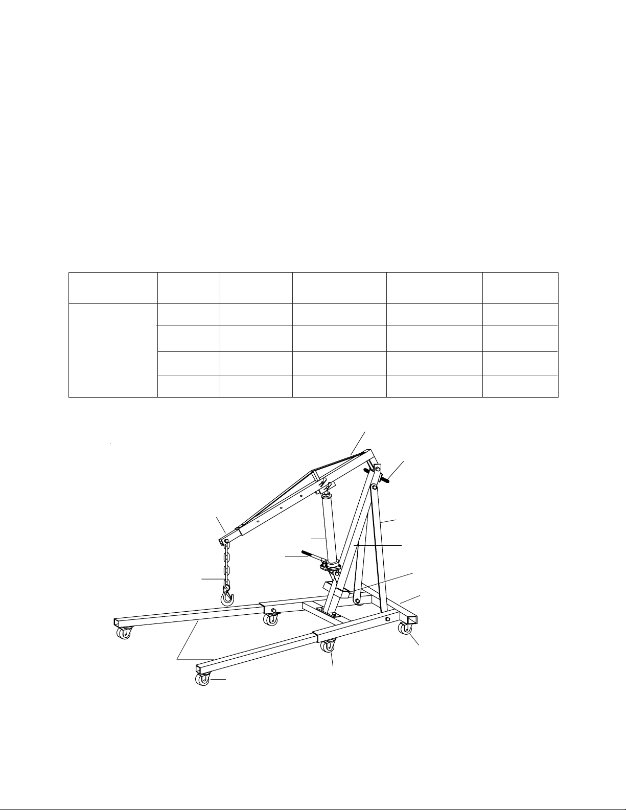
Boom extension
Chain/hook
assembly
Capacity
1 Ton
Hydraulic unit
Handle
18-1/2"
10"
Boom
Crane handle
Max. Hook HeightMin. Hook Height
77-1/4"
80-3/4"
84-1/2"
88-1/4"
Support strut
Upright
Leg holder
Base
Boom Length
"4/3 25noT 2
59-1/2"14-1/8"1 1/2 Ton2
66-1/8"
72-7/8"5-7/8"1/2 Ton
Leg extensions
Front caster
Middle
caster
Figure 1 - Engine Crane Nomenclature
2
Rear caster
Page 3
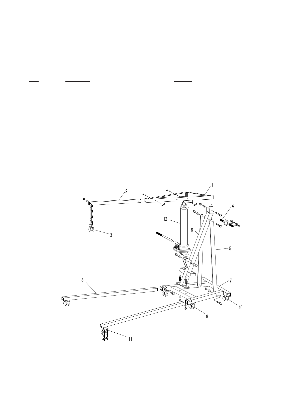
ASSEMBLY
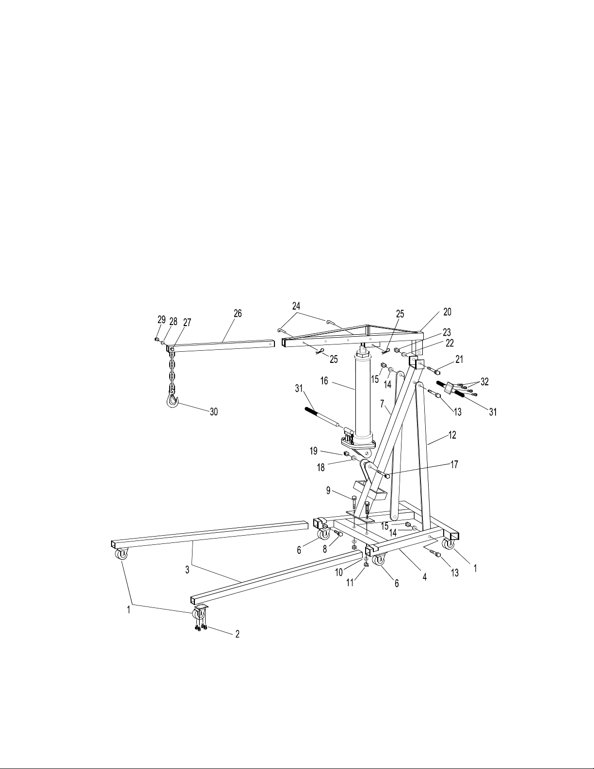
1. Attach two front casters (#1) to legs (# 3) with M8x12 bolts (# 2).
2. Attach two middle casters (#6) and two rear casters (#1) to base (#4) with M8x12 bolts (#2).
3. Slide two legs (#3) into the base (#4) and secure with M14x30 bolts (#8).
4. Attach upright (#7) to base (#4) with M14x100 bolts (#9), washers (#10) and nuts (#11).
5. Attach two strut supports (#12) to base (#4) and upright (#7) with M16x100 bolts (#13), washers (#14), and nuts
(#15).
6. Place hydraulic unit (#16) on upright’s support bracket and secure with M16 x 90 bolt (#17), washer (#18) and nut
(#19).
7. Attach boom (#20) to upright (#7) with M20x100 bolt (#21), washer (#22), and nut (#23).
8. Pump jack until ram is extended approximately 2”.
9. Allign the hole on the hydraulic ram with the mounting hole of boom and secure with the lock pin (#24) and retainer
clip (#25).
10. Slide boom extension (#26) into boom (#20) and secure with the lock pin (#24) and retainer clip (# 25).
11. Attach chain/hook assembly (#30) to boom extension (#26) with M14x80 bolt (#27), washer (#28) and nut (#29).
12. Attach handle to upright with four M8x12 bolts (#31).
Figure 2 - Assembly Illustration for Model ATD-10141
3
Page 4
BEFORE USE
1. Inspect crane before each use. Do not use if bent,
broken or cracked components are noted. Ensure that
casters/wheels and boom move freely . Check for and
tighten any loose assemblies.
2. Verify that the product and the application are compatible.
3. Before using this product, read the owner's manual
completely and familiarize yourself thoroughly with
the product and the hazards associated with its improper use.
! W ARNING
• Study , understand, and follow all instructions provided
with and on this device before operating this device.
• Do not exceed rated capacity for each boom position.
• Use the device only on a hard, level surface.
• These engine cranes are intended to be used to lift
and lower rated capacity automotive and light truck
engines. It is an aid in the removal and installation
of automotive and light truck engines.
• Only use chains and slings with a capacity equal to
or greater than that of the crane.
• If loaded crane must be moved, make certain that
load is stable, is in lowest possible position and is
moved over a smooth, hard level surface.
• A void shock loads caused by the rapid opening and
closing of release valve.
• Shock loads may cause the load to swing, causing
the crane to flip violently , bend or break.
• Ensure the boom is fully lowered before checking or
adding fluid to the hydraulic unit.
• Never extend boom extension beyond furthest
distance of leg extension.
• Do not stand over loaded boom nor in its intended
line of travel.
• Do not use adapters or accessories that are not
provided initially .
• Do not use the device for any purpose other than
that for which it is intended.
• Do not modify this device.
• Failure to heed these markings may result in
personal injury and/or property damage.
OPERATION
! SAFETY MESSAGE !
• Lift only on areas of the engine as specified by
the vehicle manufacturer.
• Be sure all tools and personnel are clear before
lowering load.
1. Load capacity should be coordinated with boom
extension and legs extension. Do not extend boom
extension beyond the marking that coordinate with
the legs extension.
2. Ensure application is compatible with product.
3. Secure engine to chain/sling hook assembly , ensuring
load is centered.
4. Follow vehicle service manual recommendations to
remove engine. When ready to remove engine, turn
release valve clockwise until firm. Pump handle until
load is high enough to clear vehicle.
5. Immediately upon removal and when clear of the
vehicle, lower the load to the lowest practical position
by turning the release valve lever counter-clockwise
slowly and carefully .
Note: Avoid rolling the loaded engine crane. To help
position an engine stand if necessary , move only across
smooth, level, seamless surfaces.
Before moving ensure the load:
a. is lowered to the lowest practical position, but
always below the center of gravity .
b. is prevented from swinging and inadvertent shifting.
5. Position a suitable engine stand near the removed
engine, then immediately transfer the load to
appropriate engine support device (engine stand).
6. Check to ensure stand is secure before working on or
around.
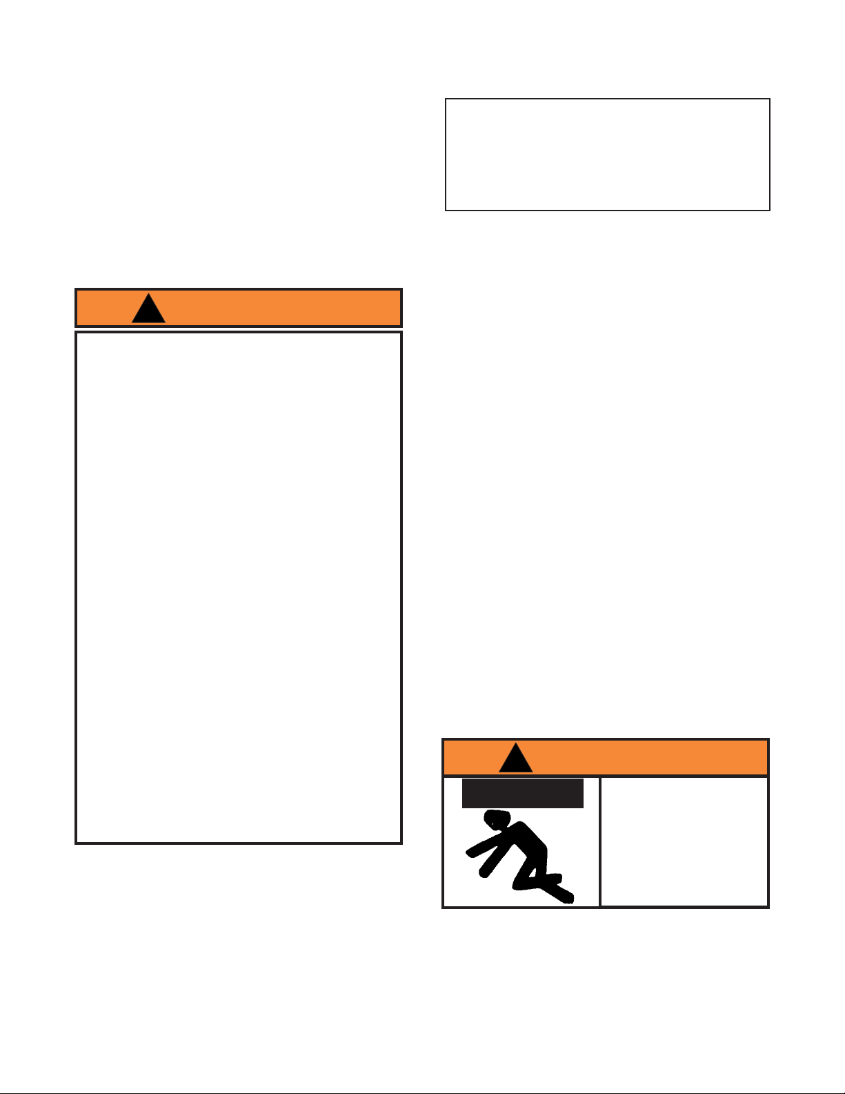
! W ARNING
T o avoid crushing and
related injuries:
NEVER work on, under or
around a load supported
only by a crane.
Immediately transfer the
load to an appropriately
rated engine stand.
4
Page 5
MAINTENANCE
Important: Use only a good grade hydraulic jack oil.
Avoid mixing different types of fluid and NEVER use
brake fluid, turbine oil, transmission fluid, motor oil or
glycerin. Improper fluid can cause failure of the jack and
the potential for sudden and immediate loss of load. We
recommend Mobil 13M or equivalent.
Adding oil
1. Carefully remove hydraulic jack from crane.
2. With ram fully lowered and pump piston fully
depressed, set jack in its upright, level position.
Remove oil filler plug.
3. Fill with oil until just below the rim of the oil filler
plug hole. Reinstall the oil filler plug.
Changing oil
For best performance and longest life, replace the
complete fluid supply annually .
1. Carefully remove hydraulic jack from crane.
2. With ram fully lowered and pump piston fully
depressed, set jack in its upright, level position.
Remove oil filler plug.
3. Lay the jack on its side and drain the fluid into a
suitable container .
Lubrication
A periodic coating of light lubricating oil to pivot points,
axles and hinges will help to prevent rust and assure that
wheels, casters, and pump assemblies move freely .
Cleaning
Periodically check the pump piston and ram for signs of
rust or corrosion. Clean as needed and wipe with an oily
cloth.
Note: Never use sandpaper or abrasive material on
these surfaces !
Storage
1. When not in use, store the jack with pump piston
and ram fully retracted.
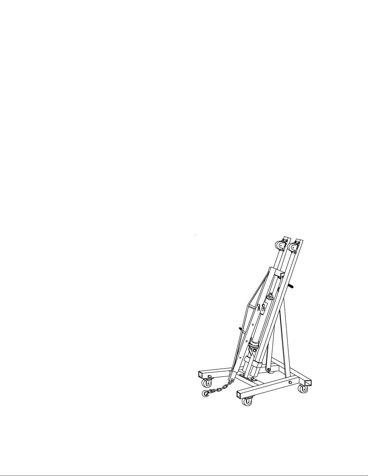
2. To transform the crane into storage position:
a. Remove lock pin (#24 on figure 2) from boom.
b. Lean hydraulic unit back against upright and
slowly lower the boom to rest against hydraulic
unit.
c. Remove bolts (#8 on figure 2) of left and right legs
of the crane.
d. Remove legs from crane and keep it in the leg
holder at each side of upright.
Note: Dispose of hydraulic fluid in accordance with
local regulations.
4. Set jack in its level upright position.
5. Fill with oil until just below the rim of the oil filler
plug hole. Reinstall the oil filler plug.
Figure 3 - Engine Crane Storage Position
5
Page 6

TROUBLESHOOTING
Symptom Corrective Action
Jack will not lift load
Jack *bleeds off after lift
Jack will not lower after unloading
Poor lift performance
Jack will not lift to full extension
• Release valve not tightly closed
• Overload condition
• Release valve not tightly closed
• Overload condition
• Hydraulic unit malfunction
• Reservoir overfilled
• Fluid level low
• Air trapped in system
• Fluid level low
Possible Causes
• Ensure release valve tightly closed
• Remedy overload condition
• Ensure release valve tightly closed
• Remedy overload condition
• Replace hydraulic unit
• Drain fluid to proper level
• Ensure proper fluid level
• With ram fully retracted, remove oil
filler plug to let pressurized air
escape, then reinstall oil filler plug.
• Ensure proper fluid level
* "Bleeding off" means that jack begins to slowly lower rather than keep load at height.
6
Page 7
REPLACEMENT PARTS
Not all components of the crane are replacement items, but are illustrated as a convenient reference of location and
position in the assembly sequence. When ordering parts, give the model number, serial number and parts description.
Model ATD-10141
Item Description Quantity
1 mooB10
1 noisnetxe mooB20
1 ylbmessa kooh dna niahC30
1 eldnaH enarC40
2 turts troppuS50
06 Upright 1
1 esaB70
2 geL80
2 retsac elddiM90
2 retsac raeR01
2 retsac tnorF11
1 tinu ciluardyH21
- Hardware kit all bolts & nuts
-)s(lebaL-
-launaM-
Figure 4 - Replacement Parts Illustration for Model ATD-10141
7
Page 8

ONE YEAR LIMITED WARRANTY
For a period of one (1) year from date of purchase, Atd Tools Inc. will repair or replace, at its option, without charge,
any of its products which fails due to a defect in material or workmanship, or which fails to conform to any implied
warranty not excluded hereby.
Performance of any obligation under this warranty may be obtained by contacting your point of sale and obtaining return
or repair information from your supplier.
Except where such limitations and exclusions are specifically prohibited by applicable law, (1) the CONSUMER'S
SOLE AND EXCLUSIVE REMEDY SHALL BE THE REPAIR OR REPLACEMENT OF DEFECTIVE PRODUCTS AS
DESCRIBED ABOVE, and (2) Atd Tools Inc. SHALL NOT BE LIABLE FOR ANY CONSEQUENTIAL OR INCIDEN-
TAL DAMAGE OR LOSS WHATSOEVER, and (3) THE DURATION OF ANY AND ALL EXPRESSED AND IMPLIED
WARRANTIES, INCLUDING WITHOUT LIMITATION, ANY WARRANTIES OF MERCHANTABILITY AND FITNESS
FOR A PARTICULAR PURPOSE, IS LIMITED TO A PERIOD OF ONE (1) YEAR FROM DATE OF PURCHASE.
Some states do not allow limitations on how long an implied warranty lasts, so the above limitation may not apply
to you. Some states do not allow the exclusion or limitation of incidental or consequential damages, so the above
limitation or exclusion may not apply to you. This warranty gives you specific legal rights, and you may also have
other rights which vary from state to state.
Atd Tools Inc.
160 Enterprise Drive,
Wentzville MO 63385
636-327-9050
 Loading...