

Page 1
TH-UWM
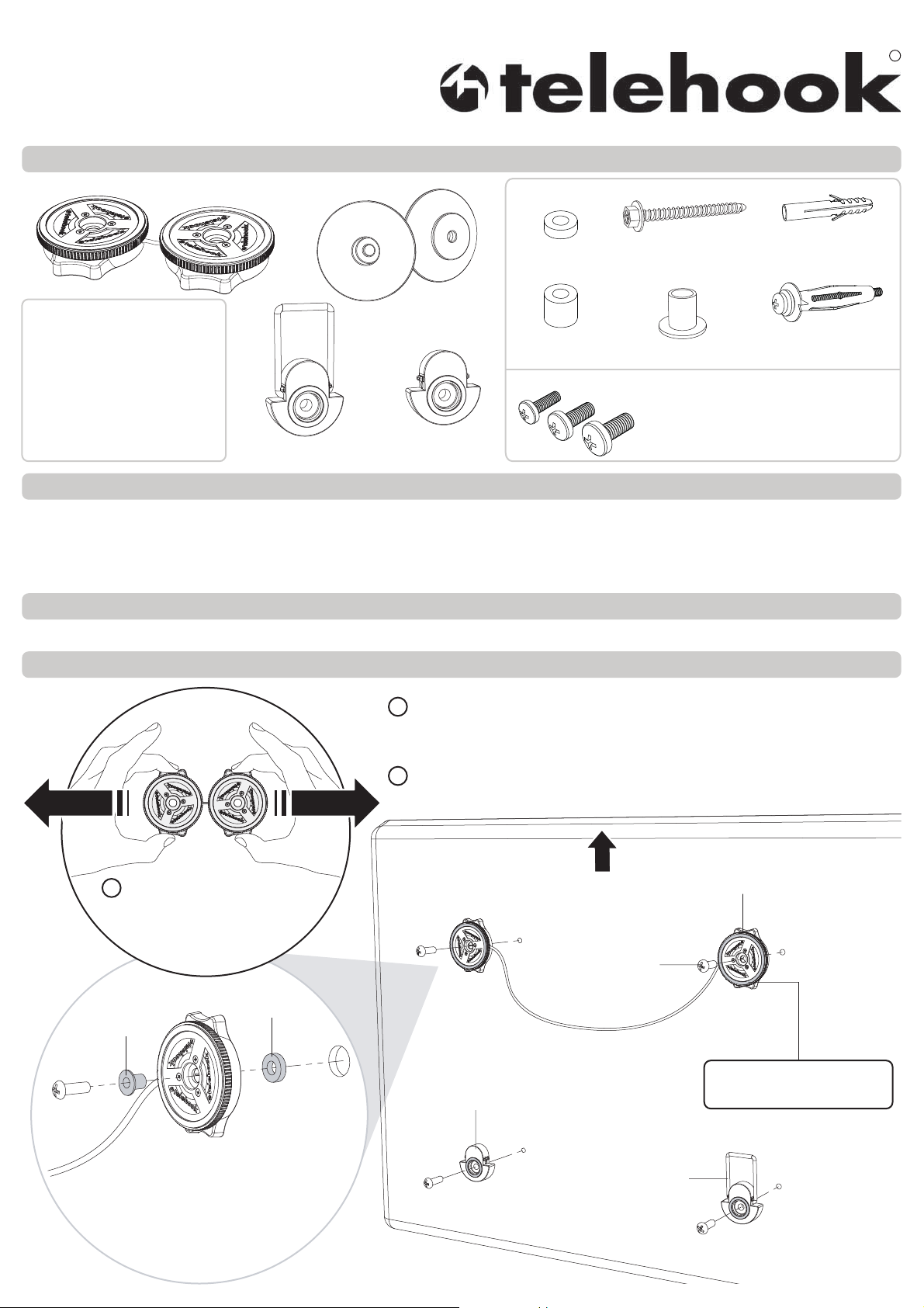
Component Checklist
Installation Instructions
Universal Wire Mount
TM
Wire Reel Assembly
Hardware
Short
Spacer (x4)
Flange
Screw (x2)
Hook Plates
Tools Required:
Phillips head screwdriver
Power drill
4.5mm (
10mm (
10mm (
10mm (
3
/16”) drill bit
3
/8”) masonry drill bit
3
/8”) drill bit
3
/8”) socket wrench
Spirit level
Cable Access Support
(x2)
Lower Support
Long
Spacer (x4)
M5 Bush (x2)
Display Mounting Screws:
M5 x 16mm / M5 x 25mm (x4 each)
M6 x 16mm / M6 x 25mm (x4 each)
M8 x 16mm / M8 x 25mm (x4 each)
IMPORTANT INFORMATION
! IMPORTANT - Install Telehook Universal Wire Mount as per Installation Instructions.
!
This product supports a maximum load of 50kg (110lbs).
!
This product supports VESA and Universal mounting hole configurations from 200mm up to 800mm wide (8”-31.5”).
! The manufacturer accepts no responsibility for incorrect installation.
Step 1. Check Components
Check you have received all parts against the Component Checklist and Hardware above.
Concrete
Anchor (x2)
Dry Wall
Anchor (x2)
Step 2. Fix Universal Wire Mount to Display
PULL
FIRMLY
1 Grip the Wire Reel Assembly
as shown above. Pull firmly to
release wire to suit the Display
mounting hole pattern.
Spacer
M5 Bush
2 Select the appropriate hardware (supplied) to fasten the Wire Reels
LOOSELY to the back of the Display. Use top two mounting holes.
TIP: Only screw in half-way.
3 Fasten Cable Access Support and Lower Support FIRMLY to the
bottom two mounting holes.
TOP
Wire Reel
Mounting Screw
Lower
Support
NOTE: All orange pads
should be facing outwards.
OPTIONAL: Use Short or Long Spacers
to pack recessed mounting holes. When
using M5 Mounting Screws use
the M5 Bushes supplied.
Cable
Access Support
Page 2

Step 3. Tension Wire
2 Fully tighten the Mounting Screws through both Wire Reels.
This will engage the internal reel lock mechanism.
TIP: Tighten as FIRMLY as possible.
Mounting Screw
CLICK
1 Grip the lower half of the Wire Reel.
With your other hand twist the top,
taking in any slack in the wire
(repeat for opposite Wire Reel).
3 For extra wire tension, twist the Wire Reels
in opposite directions (shown above).
TIP: Re-tighten Mounting Screws if necessary.
Step 4. Mount Hook Plates on Wall
Choose from one of the following mounting options (below): Timber Stud, Masonry Wall, or Dry Wall. Fasten the Hook Plates
to the wall, 150-500mm (6”-20”) apart (to suit wire length), using the appropriate mounting hardware supplied.
Timber Stud Masonry Wall
Dry Wall 10-13mm (0.4”-0.5”) thick.
Ensure Dry Wall is in good condition,
Concrete Anchor
with no sign of water damage or cracking.
Hook Plate (x2)
Flange Screw
(x2)
Drill two holes 60mm deep using a
4.5mm
(3/16”)
drill bit.
Drill two holes 60mm (2.36”) deep using
a 10mm
(3/8”)
masonry drill bit.
Flange Screw
(x2)
Drill two holes using a 10mm
drill bit.
Step 5. Hang Display on Wall Step 6. Cable Management
1 Gently lower the display until the wire is hanging over
the Hook Plates.
Spirit level
1 Pull the bottom edge of the Display away from the wall
and fold out Cable Access Support.
2 Connect cables.
Dry Wall Anchor (x2)
(3/8”)
2 Use a spirit level to ensure the Display is hanging correctly.
Installation Complete
No portion of this document or any artwork contained herein should be reproduced in any way without the express written consent of Atdec Pty Ltd.
Due to continuing product development, the manufacturer reserves the right to alter specifications without notice. Published 16.05.11 ©
WALL
Cable Access
Support
3 Fold in Cable Access Support to return the Display to flat
against the wall.
 Loading...