

Page 1
TH-PF
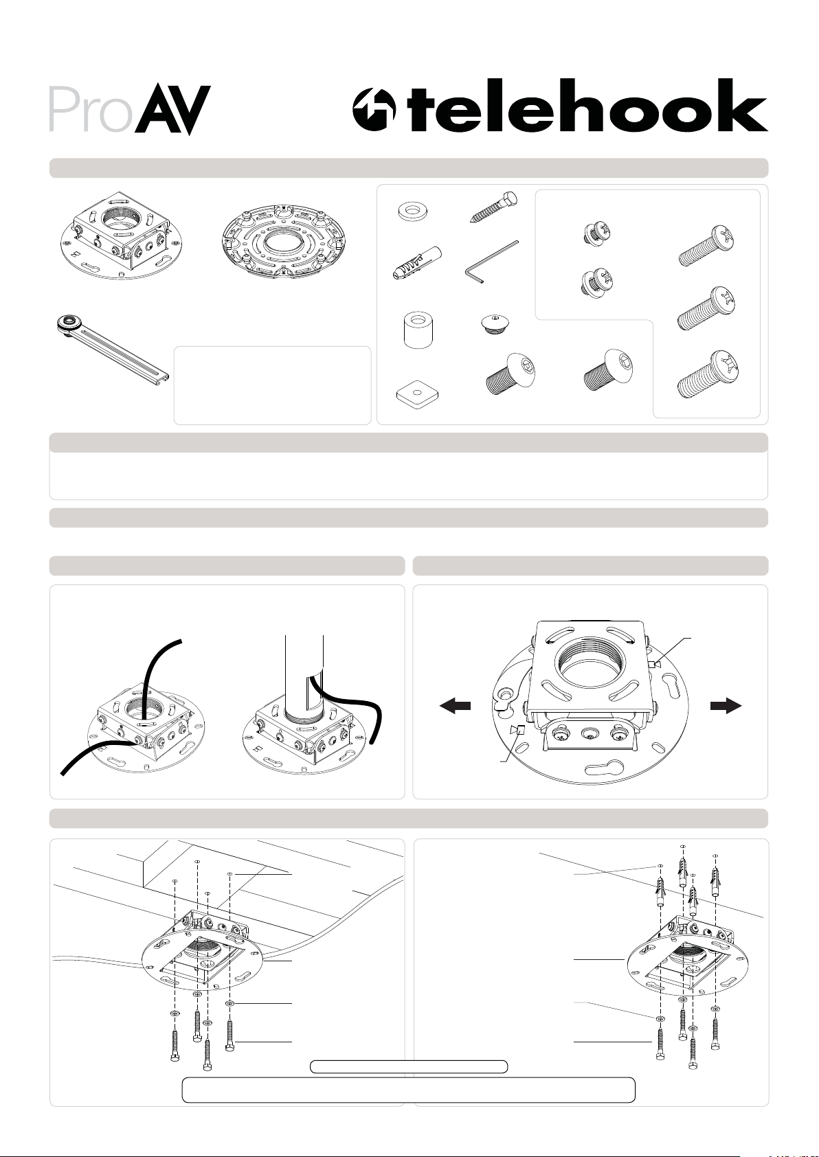
Component Checklist
Installation Instructions
Pro AV Projector Ceiling Mount
Mount
Leg (x4)
Base Plate
Tools Required:
• Power Drill
• 4mm(0.15”) Drill Bit
• 9mm(0.35”) Masonry Drill Bit
• Phillips Head Screwdriver
• 13mm (0.5”) Socket Wrench/ Shifter
HARDWARE
M6 Washer (x4)
Nylon
Anchor (x4)
10mm Spacer
(x4 each)
Square Nut (x4)
Coach Bolt (x4)
3mm Security
Allen Key
Security Cap (x4)
M5x10mm
Security Screw
Projector Mounting Screws (x4 each)
M2.5x15mm w/ Washer
M3x15/20mm w/ Washer
M5x10mm Socket
Head Screw (x4)
IMPORTANT INFORMATION:
! IMPORTANT - Install Telehook Projector Ceiling Mount as per installation instruction.
! This product supports a maximum load of 25kg (55lbs.).
! The manufacturer accepts no responsibility for incorrect installation.
Step 1. Check Components
Check you have received against the component checklist and hardware above.
Step 2. Cable Management
Step 3. Choosing Orientation
M4x15/20/25mm
M5x15/20/25mm
M6x15/20/25mm
The TH-PF can be mounted flush to a ceiling (Step 4) or to a pole (Step 5).
Before mounting your TH-PF, give consideration to your cable route. The
TH-PF has provision for cable management as shown below.
Ensure the Mount is attached with the Projector Marks pointing in the same
direction that the projector will be facing.
Projector Mark
Step 4. Ceiling Mount
Timber Stud Masonry
Ø4mm x 35mm deep
Drilled Hole
Mount
Projector Mark
Ø9mm x 40mm deep
Drilled Hole
Mount
M6 Washer
Coach Bolt
TIP: Use Mount as a drilling template.
IMPORTANT! Any structural elements must be capable of supporting the combined weight of
all the equipment and devices being mounted. If in doubt, consult a structural engineer.
M6 Washer
Coach Bolt
Page 2
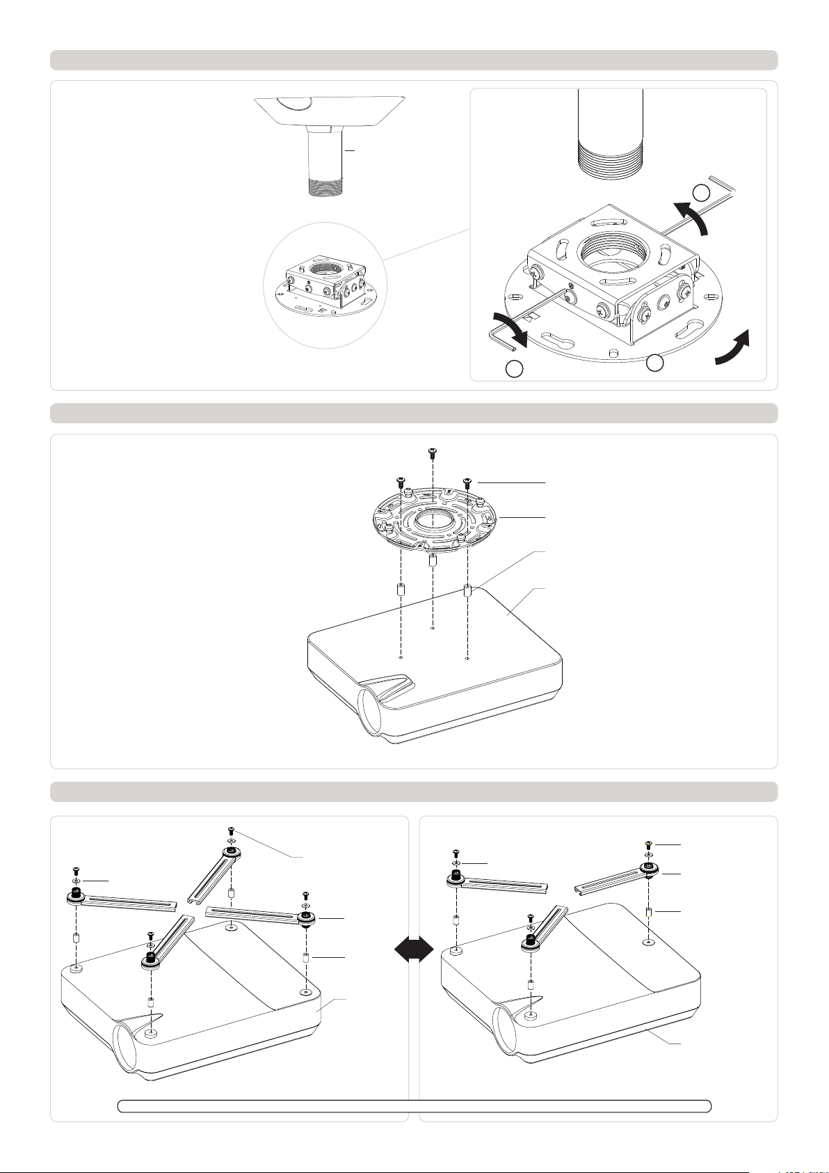
Step 5. Pole Mount
1. Install Pole Accessory.
2. Thread mount fully into the end of the Pole.
3. Set the orientation by unwinding the mount. Do
not unwind the mount more than one full turn.
4. Lock the mount in place by tightening the two
security set screws in place using the supplied
security allen key.
Note: The TH-PF is compatible with 1.5NPT thread.
A range of Pole Accessories are available from Atdec.
Step 6. Mounting Projector
Depending on the size of your projector, the
TH-PF has several mounting options available.
Smaller Projectors can be mounted directly to
the Base Plate.
For all other projectors, use the supplied legs.
Pole Accessory
(Purchased separately
or as part of a kit
from Atdec)
4 TIGHTEN
Projector Mounting
Screw
Base Plate
Spacer (optional)
4 TIGHTEN
2 MOUNT
Step 7. Attach the Legs to the Projector
FOUR FIXING POINTS THREE FIXING POINTS
Washer (optional)
Projector Mounting
Screw
Leg
Spacer
(optional)
OR
Washer (optional)
Projector
Projector Mounting
Screw
Leg
Spacer (optional)
Projector
Note: Washers must be used in conjunction with M2.5 and M3 projector mounting screws.
Projector
Page 3

Step 8. Height Adjustment
If the surface of the projector is uneven the height of the legs can
be adjusted to allow the legs to level with each other by turning
the dial on the leg.
7mm Max.
Note: if a difference in height of over 7mm is present use the
spacers provided
Rotate the dial of the Leg counter-clockwise to increase height and
clockwise to decrease height.
- HEIGHT
Step 9. Insert Security Caps Step 10. Insert Square Nuts
Insert Security Cap and tighten using the supplied 3mm Security Allen Key.
Insert one Square Nut to each leg.
+ HEIGHT
Security Cap
INSERT
Square Nut
Step 11. Base Plate Orientation Step 12. Attach Base Plate
M5x10mm Socket
Head Screw
Base Plate
Studs
Square Nut
(inside the Leg)
1. The four studs on the Base Plate should point along the axis
of the projector.
2. Position the Base Plate centrally towards the heaviest part of
the projector so that the weight of the projector is centred and
balanced after mounting.
Use the supplied 3mm Security Allen Key to tighten the four screws.
Page 4

Step 13. Attach Projector to Mount
Keyhole
Keyholes
Studs
Insert the four studs to the key holes and Rotate the projector.
Step 13. cont.
Studs
Insert the four studs in
the key holes
1 INSERT
Step 14. Security
To secure the base plate insert the M5 x 10mm Security Screw into any
of the four locking holes and tighten using the supplied 3mm Security
Allen key
Locking Holes
2 ROTATE
Rotate the projector to engage the spring catch
M5x10mm Security Screw
Locking Holes
Page 5

Step 15. Roll Adjustment
Step 16. Tilt Adjustment
Loosen Phillips Head Screws 1-4 for Roll Adjustment of ±5° and
tighten to fix position.
5
1
FRONT
BACK BACK
2
6
1
FRONT VIEW
2
+5°
-5°
TOP VIEW
Loosen Phillip Head Screws 5-8 for Tilt Adjustments of ±20° and
tighten to fix position.
7
3
FRONT
4
8
6
SIDE VIEW
Note: When mounting
the projector mount
flush to a ceiling,
depending on the
size and shape of the
projector a maximum
tilt of ±10° can be
achieved.
8
-20°
+20°
Installation Complete
Removing the projector from mount (Warning care needed to remove projector)
1. Remove security screw installed in STEP 14
2. Pull up spring catch.
3. Move the projector round so the stud is partially out the hole.
4. Carefully rotate the projector to the end of the keyhole. When
the stud reaches the end of the key hole the projector will be unsupported. Be ready to take the weight of the projector and lower it
down away from the mount.
No portion of this document or any artwork contained herein should be reproduced in any way without the express written consent of Atdec Pty Ltd.
Due to continuing product development, the manufacturer reserves the right to alter specifications without notice. Published 30.01.13 ©
 Loading...