

Page 1
Installation Instructions
TH-2050-UFL
Small-Medium TV Articulated Arm
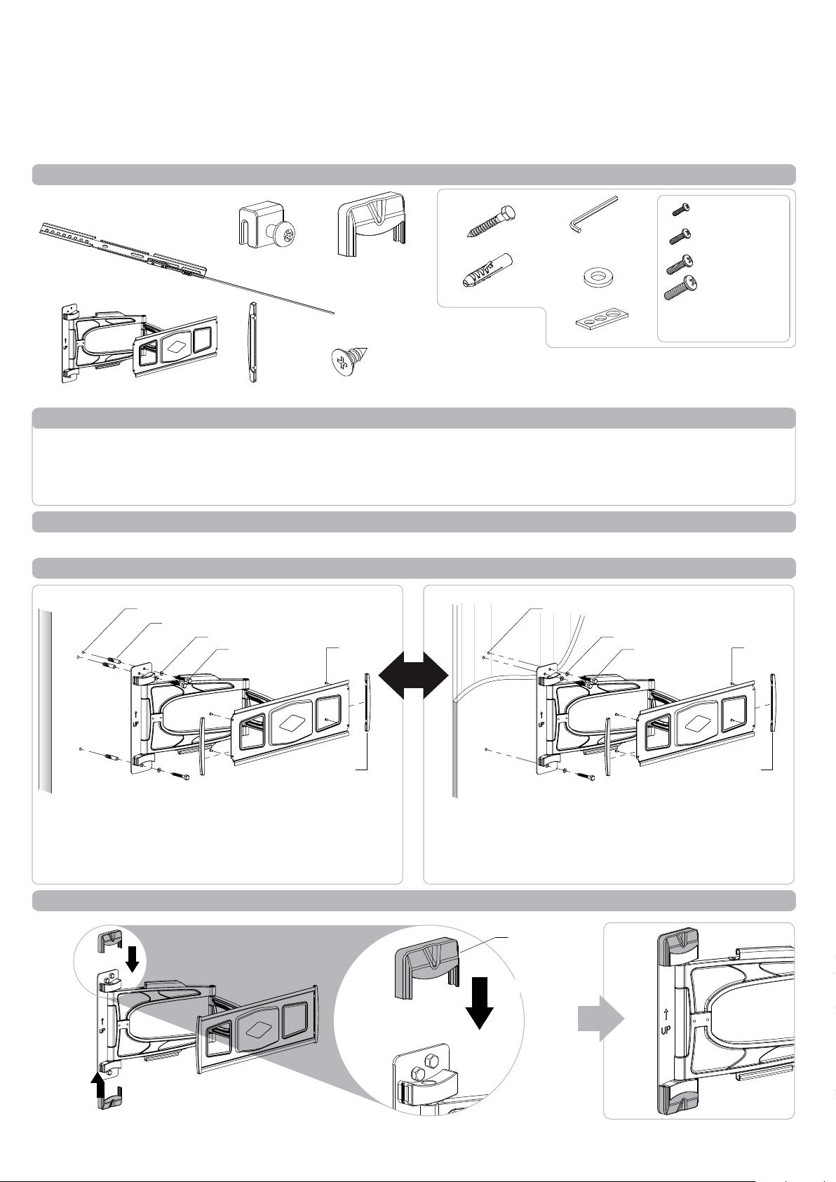
Component Checklist
Mounting Bracket (x2)
Arm/Wall Mount
Locking Block (x2)
End Cap (x2)
Top Cap (x2)
End Cap Screw (x4)
Hardware
Coach Screw (x3)
Nylon Anchor (x3)
Tools Required:
Power drill
•
4.5mm (0.18”) drill bit
•
10.5mm (0.41”) masonry drill bit
•
Phillips head screw driver•
10mm (0.39”) socket wrench or shifter
•
13mm (0.5”) socket wrench or shifter
•
Allen Key
Washer (x3)
Multiwasher (x4)
4mm
M4x16mm
M5x16mm
M6x16mm/25mm
M8x16mm/25mm
Display Mounting
Screws (x4 each)
IMPORTANT INFORMATION:
! IMPORTANT - Install 2050 Small-Medium TV Articulated Arm per Installation Instructions.
! This product supports a maximum load of 25kg (55lbs).
! This product supports VESA mounting hole configurations 200mm wide x100mm high to 400mm wide x 400mm high.
! The manufacturer accepts no responsibility for incorrect installation.
Step 1. Check Components
Check you have received all parts against the Component Checklist and Hardware above.
Step 2. Install Arm/Wall Mount to the Wall
Masonry Wall
Drilled Hole
Nylon Anchor
Washer
Coach Screw
End Cap
Screw
Timber Stud Wall
OR
End Cap
- Drill three 10.5mm (0.41”) diameter holes,
58mm (2.3”) deep.
- Secure the mounting plate to the wall using the Coach
Screws and Nylon Anchors supplied.
- Drill three 4.5mm (0.18”) diameter holes, 58mm (2.3”) deep.
- Secure the mounting plate to the wall using the Coach
Screws supplied.
NOTE: Use a stud finder to accurately locate the centre
of the stud. Ensure that all screws fix securely into stud.
Step 3. Attach Top Caps to the installed Arm/Wall Mount
Drilled Hole
Washer
Coach Screw
End Cap
Screw
End Cap
SLIDE
Top Cap
SLIDE
SLIDE
Page 2
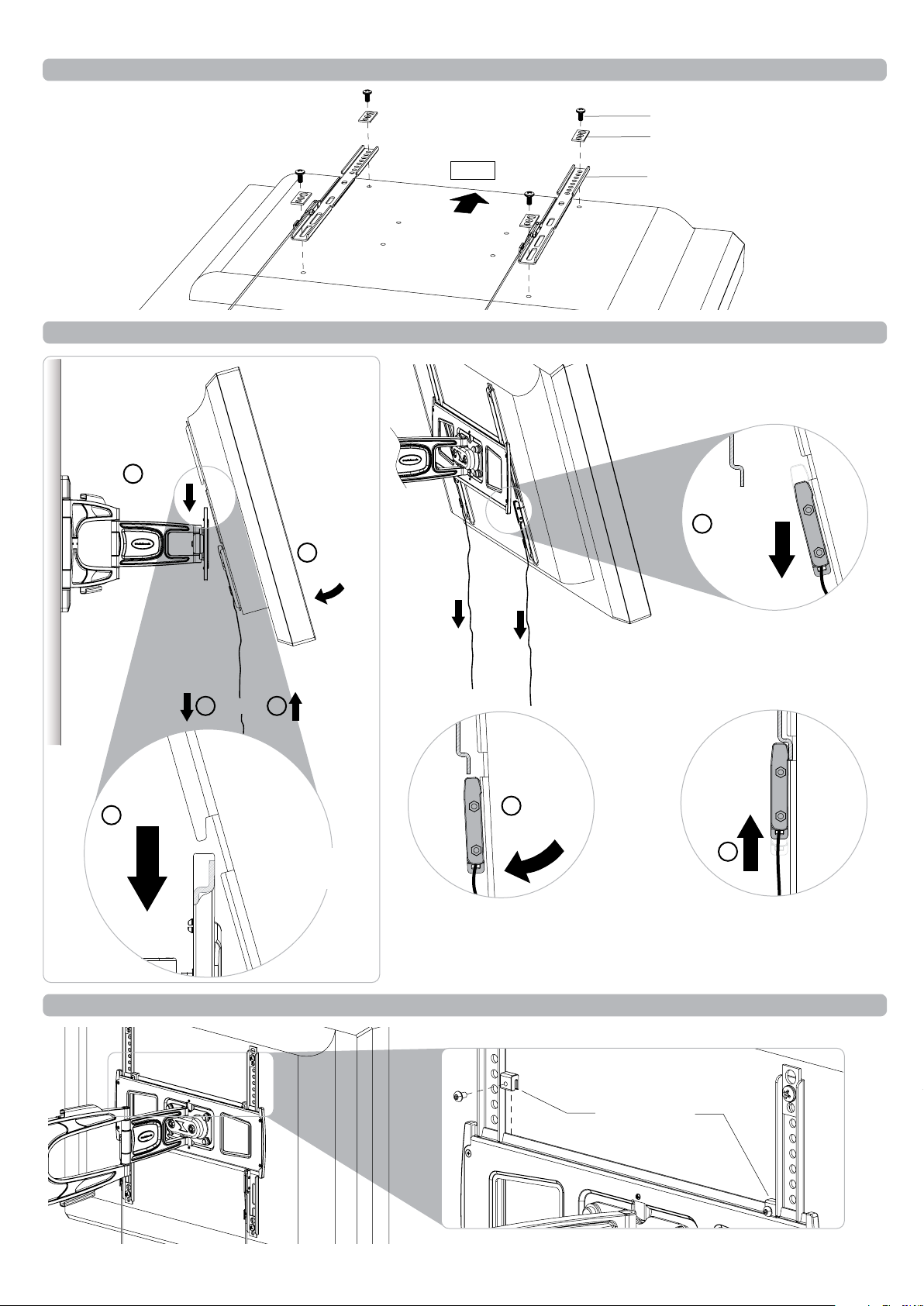
Step 4. Attaching Mounting Brackets to Display
The mounting brackets support
hole configurations from
200x100mm to 400x400mm.
TOP
Back of Display
Display Mounting Screw
Multiwasher
Mounting Bracket
Step 5. Attaching/Detaching Display to the installed Arm (2 people required)
WALL
1 HOOK
2 PULL
3 PUSH
DOWN
DOWN
2 LOCK 4
1 HOOK
Hook the Display
to the Arm/Wall
Mount.
Push down Display into catch. Release Spring Lock Ties
3 PUSH
DOWN
Step 6. Attach Locking Blocks to fully secure the Display
Pull down both Spring Lock
Ties to open catch.
RELEASE 4
to secure Display.
NOTE: Ensure that Spring
Lock is fully engaged.
Back of Display
Locking Blocks
Page 3

Step 7. Adjust Arm movement if necessary
±90°
±180°
WALL
4mm Allen Key
Step 8. Adjust tilt and roll if necessary
+15°
-5°
Back of Display
±90°
LOOSEN
(-kg)
TIGHTEN
(+kg)
Position your display to the
desired viewing angle, using the
angular movement allowed by
the double ball mount.
Depending on the weight of the
Display, it may be necessary to
make adjustments to the double
ball mount. If the display does
not hold its position, or is too
resistant, adjust the tension
plate located at the rear of the
double ball mount.
To adjust the tension plate, apply
half a turn at a time to each nut.
ENSURE NUTS ARE ADJUSTED
EVENLY.
Socket Wrench
±5°
CHECK THE DISPLAY, and then
adjust again if necessary.
Step 9. Cable Management
Back of Display
Installation Complete
No portion of this document or any artwork contained herein should be reproduced in any way without the express written consent Atdec Pty Ltd.
Due to continuing product development, the manufacturer reserves the right to alter specifications without noticed. Published 2
6.04.12 ©
 Loading...