

Page 1
TH-1040-CTS
TH-1040-CTL
TH-1040-CTSW
TH-1040-CTLW
Component Checklist
Installation Instructions
Ceiling Tilt Short Mount / Ceiling Tilt Long Mount
Hardware
Mounting Plate
Mounting Plate Cover
Tools Required:
Power drill
•
7mm
(¼”)
•
•
•
12mm
Phillips head screw driver•
17mm (
drill bit
(½”)
masonry drill bit
11
/16”) Socket Wrench or Shifter
False Ceiling Cover
VESA Plate
Pole Assembly
Coach Screw (x4)
Nylon Anchor (x4)
M4/5 Spacer (x4)
(optional) Security Screw
M4/5/10 Washer
M5/6 Spacer (x4)
2.5/3/5mm
Allen Key
(x4 each)
Set Screw
M4x16/25mm (x4 each)
M5x16/25mm (x4 each)
M6x16/30mm (x4 each)
Display Mounting
Screws
IMPORTANT INFORMATION:
! IMPORTANT - Install Telehook 1040 Ceiling Tilt Mount (Short/Long) as per Installation Instructions.
! This product supports a maximum load of 25kg (55lbs).
! This product supports VESA mounting hole configurations 75x75mm, 100x100mm, 200x100mm, 200x200mm.
! The manufacturer accepts no responsibility for incorrect installation.
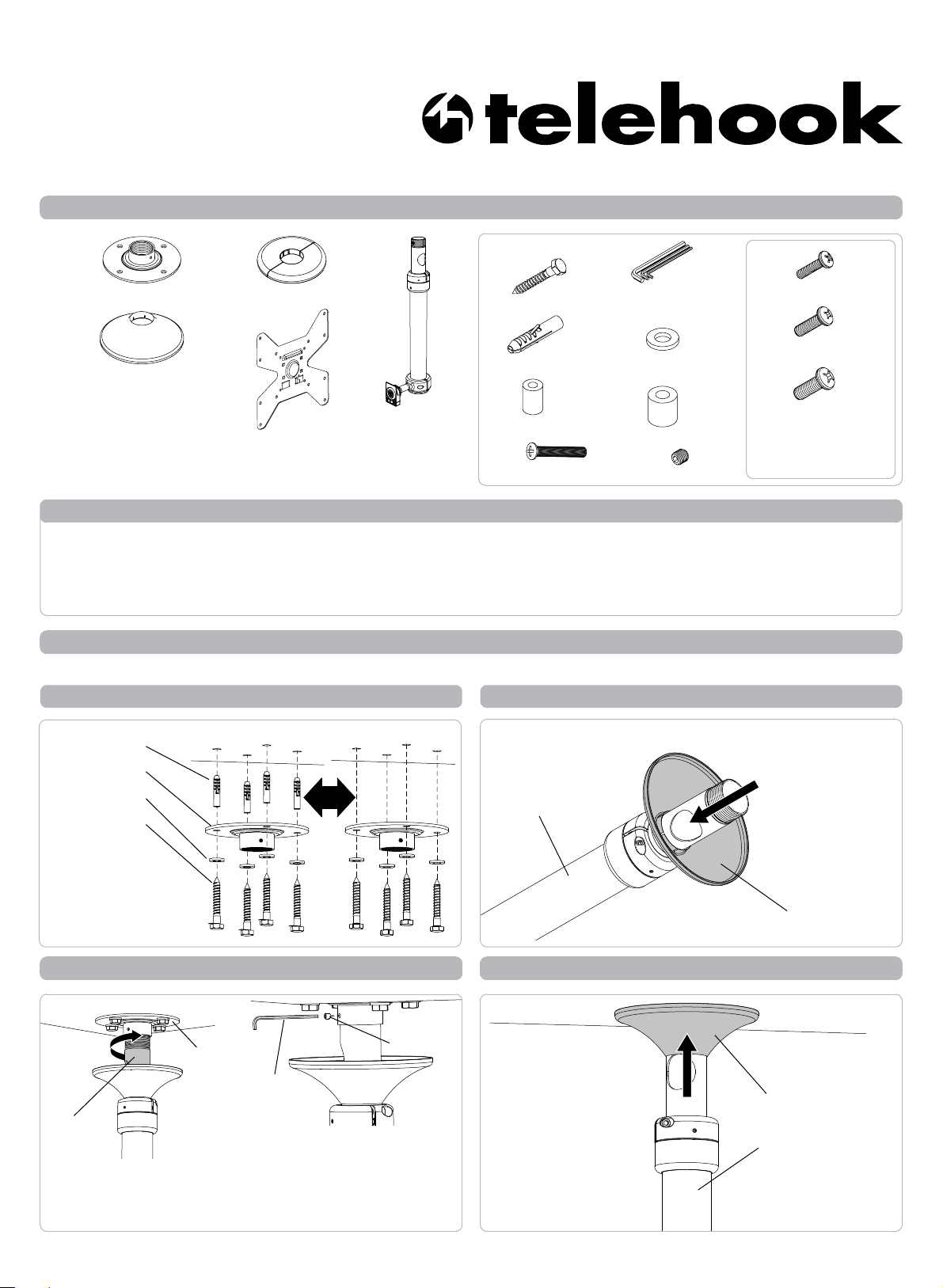
Step 1. Check Components
Check you have received all parts against the Component Checklist and Hardware above.
Step 2. Install Mounting Plate
Nylon Anchor
Mounting Plate
M10 Washer
Coach Screw
Masonry Ceiling
OR
Timber Ceiling
Step 3. Install Mounting Plate Cover
PUSH
Pole Assembly
Using the Mounting
Plate
as a template, mark
out
and drill
(¼”)
holes,
for masonry
70mm
Step 4.
TWIST
Pole
Assembly
A.
4x Ø7mm
Ø12mm
(2.75”)
ceilings,
deep.
(½”)
Attach Pole Assembly to Mounting Plate
Mounting Plate
Screw Pole Assembly
into Mounting Plate by
twisting top half of the
Pole Assembly only.
Mounting Plate Cover
Step 5. Position Mounting Plate Cover
Set Screw
3mm
Allen Key
Insert Set Screw into the
B.
Mounting Plate to lock the
Pole Assembly in position.
PUSH
Mounting Plate
Cover
Pole Assembly
Page 2
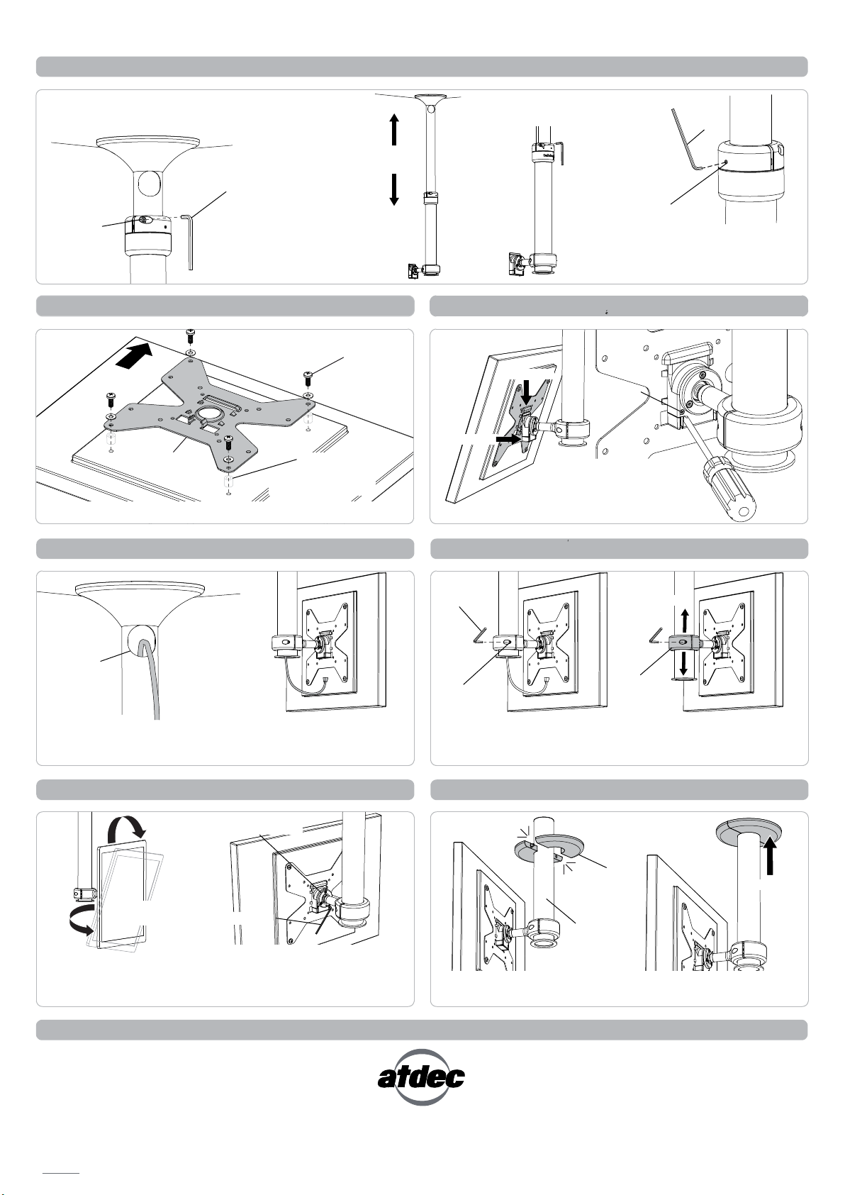
Step 6. Set Height of Pole
A.
Whilst supporting the lower half of Pole
Assembly loosen
Socket Cap
Screw
the
Socket Cap Screws (x2).
5mm Allen Key
LOOSEN
ADJUST
HEIGHT
B.
Slide Pole Assembly
to the desired height.
C.
Tighten the Socket Cap
Screws (x2) to set the height.
TIGHTEN
FIRMLY
D.
Pole Joint by tightening the
Set Screws (x2) to suit.
2.5mm
Allen Key
Pole Joint
Set Screw
If necessary, centralise the
Step 7. Attach VESA Plate to Display
TOP
VESA plate
Choose the appropriate
mounting hardware to suit the Display.
Spacers
(optional, for recessed
mounting holes)
Step 9. Cable Management
Cable
Access Port
A.
Feed cables down the Pole
Assembly through the Cable
Access Port.
B.
Pull cables out from lower
half of the Pole Assembly
connect to Display.
Mounting
Screws
and
Step 8. Attach Display to Pole Assembly
HOOK
A.
Security
Screw
B. PUSH
(optional) Once Display
C.
is attached, insert
Security Screw using
Phillips-head screwdriver
Step 10. Height Adjustment
5mm
Allen Key
Socket Cap
Screw
A.
Loosen Socket Cap
Screws (x2) on the Donut.
SLIDE
Donut
B. Slide
Donut
the height of the
as required. Tighten
Socket Cap Screws to lock.
Step 11. Final Adjustment
VESA Ball Mount
Tension Plate at rear
3mm Allen Key
B.
Ball
Tension Plate. Using the 3mm
Allen Key adjust screws evenly.
PAN
A. Pan,
Tilt and Rotate
the Display as
TILT
PORTRAIT TO
LANDSCAPE
required.
If necessary tighten the VESA
Mount by adjusting the
Step 12. Install False Ceiling Cover
CLICK
False Ceiling
Cover
Lower Pole
If the Lower Pole hangs below a suspended ceiling, clip the False
Ceiling Cover over the Lower Pole, and push up to the ceiling.
PUSH
Installation Complete
No portion of this document or any artwork contained herein should be reproduced in any way without the express written consent Atdec Pty Ltd.
Due to continuing product development, the manufacturer reserves the right to alter specifications without noticed. Published 29.09.11 ©
 Loading...