

Atdec SD-DP-420 Installation manual
SD-DP-420
SD-DP-750
SD-DP-1150
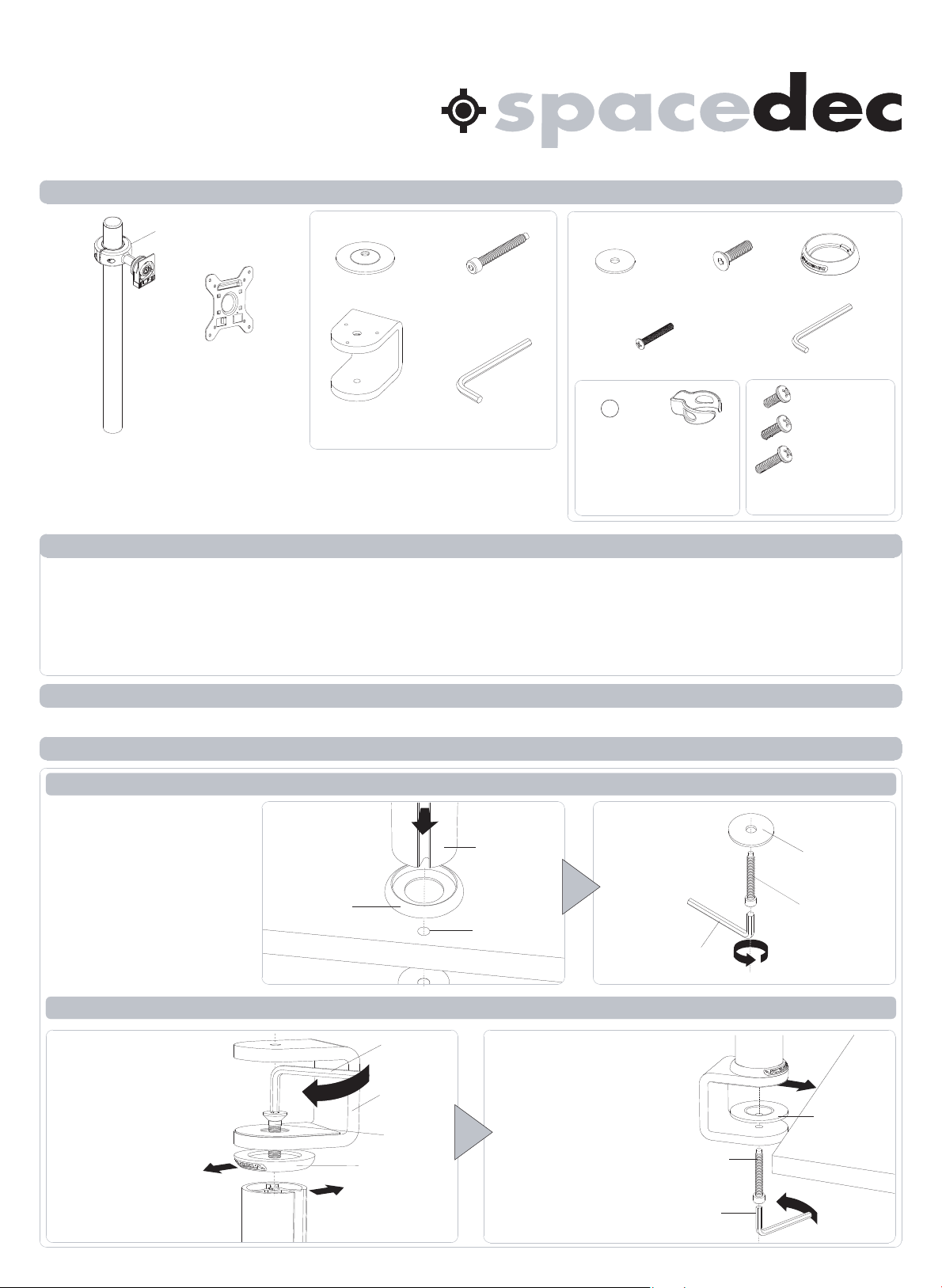
Component Checklist
Installation Instructions
Donut Pole l 420mm / 750mm / 1150mm
Quickshift Donut (x1)
VESA Plate (x1)
Donut Pole (x1)
The Donut Pole comes in three lengths
SD-DP-420 is 420mm (16.5”)
SD-DP-750 is 750mm (29.5”)
SD-DP-1150 is 1150mm (45.25”)
Desk Clamp
Pressure Plate (x1)
Desk Clamp
Bracket (x1)
TOOLS REQUIRED:
Power Drill
10mm (0.38”) Drill Bit
Phillips-head Screwdriver
M8 Desk Clamp
Screw (x1)
5mm Allen Key (x1)
Hardware
Bolt Through
Washer (x1)
(Optional) Security Screw (x1)
Cable Ball
NOTE: Quantity for:
SD-DP-420 (x2 each)
SD-DP-750 (x4 each)
SD-DP-1150 (x6 each)
IMPORTANT INFORMATION:
! IMPORTANT - Install Spacedec Donut Pole as per Installation Instructions.
! Each Quickshift Donut supports a maximum weight of 12kg (26.5lbs)
Donut Pole 420mm supports a total of 12kg (26.5lbs).
Donut Pole 750mm supports a total of 24kg (53lbs).
Donut Pole 1150mm supports a total of 36kg (79.5lbs).
! This product supports VESA mounting hole configurations: 75x75mm and 100x100mm.
! The manufacturer accepts no responsibility for incorrect installation.
M8x30mm
Screw (x1)
Cable Clip
Base Casting (x1)
3mm Allen Key (x1)
M4x10mm (x4)
M4x12mm (x4)
M4x16mm (x4)
Display Mounting
Screws
Step 1. Check Components
Check you have received all parts against the component checklist and Hardware above.
Step 2. Mounting Options
Option A. Bolt Through (Suits desktop thicknesses of 12mm - 40mm [0.5” - 1.5”])
Drill a 10mm (0.38”) hole
in the work surface at the
desired position and
assemble as shown.
Note: It is recommended
t h a t th e p o l e a s s e m b l y b e
m o u n t e d t o w a r d s th e r e a r
e d g e o f th e w o r k s u r fa c e .
Option B. De s k C l a m p (Suits desktop thicknesses of 12mm - 38mm [0.5” - 1.5”])
A t ta c h th e D e s k C l am p
B r a c k e t t o th e b o t t o m o f
th e P o l e A s s e m b l y u s i n g
th e M 8 x 3 0 m m S c r e w .
Tighte n Firm l y usi n g
th e 5 m m A l l e n K e y .
E n s u r e th e S p a c e d e c
L o g o o n th e B a s e
C a s t i n g i s fa ci n g th e
f r o n t a s s h o w n .
E n s u r e c a b l e s l o t i s
fa ci n g th e b a ck
B a s e
Ca s t i n g
W o r k s u r fa c e
Ensure cable slot
is facing back
5 m m A l le n
Ke y
D e s k C l amp
B r a c k e t
M 8 x 3 0 m m
S c r e w
B a s e C a s t i n g
P o l e A s s e m b l y
10mm (0.38”)
h o l e
A t ta c h th e D o n u t P o l e
A s s e m b l y u s i n g th e
D e s k C l am p a s sh o w n .
N ot e: D e s k C l amp
suits 12mm (0.5”)
- 38mm (1.5”) thick
w o r k su r fa c e s .
A d j u s t th e h ei g h t o f
th e P r e s s u r e P l a t e
t o s u i t y o u r w o r k
su r f ac e .
5 m m A l l e n K e y
Tighte n Firm l y
M8 Desk
Clamp Screw
5mm
A l l e n K e y
B o l t T h r o u g h
W a s he r
M 8 D e s k
C l am p S c r e w
P r e s su r e
P l at e
Work Surface
Tighten
Fi r m l y
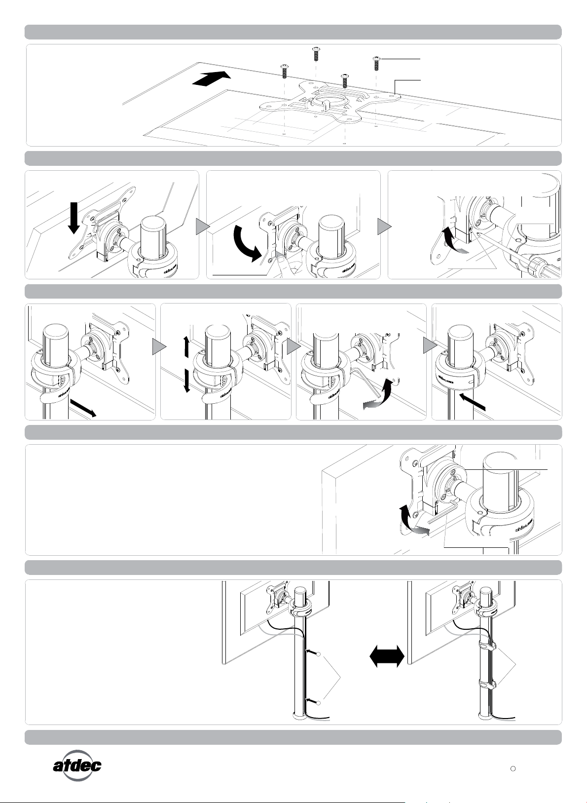
Step 3. Attach the VESA Plate to your Display
There are two mounting
hole configurations:
• 75 x 75mm
• 100 x 100mm
Top of
Choose appropriate
Mounting Screws from
the Hardware supplied
to suit your Display.
Display
75mm
100mm
Step 4. Attach your Display to the Quickshift Mount
Hook the top of the VESA plate onto the
Quickshift Mount.
HOOK
Back of Display
Press and hold the Release Buttons. Gently
push bottom of VESA Plate into Quickshift
Mount. Release Buttons to lock in place.
PUSH
Release Button
Step 5. Adjust the height of the Quickshift Donut
Open the lever to loosen the
Quickshift Donut.
Slide the Quickshift Donut to
desired position.
75mm
(Optional) Insert the Security Screw, and
tighten using a Phillips-head Screwdriver.
TIGHTEN
If necessary, adjust the tension
between the Donut and the Pole
using the 5mm Allen Key supplied.
Mounting Screws (x4)
VESA Plate
100mm
Back of Display
Security Screw
Close the lever to lock the
Quickshift Donut in place.
Phillips-head
Screwdriver
OPEN
Step 6. Adjust the VESA Ball Mount
Position your Display to the desired viewing angle using the ±20° tilt
allowed by the VESA Ball Mount.
If the display does not hold its position, or is too resistant, adjust the
Tension Plate located at the rear of the VESA Ball Mount.
To make any adjustments, use the 3mm Allen Key supplied. Apply half a
turn at a time to each screw on the Tension Plate to adjust evenly.
Check the display, and the adjust again if necessary.
Step 7. Cable Management
Connect cables to your Displays, routing
them down to the rear of the poles.
Push the cables into the slots, using either
the Cable Balls or Cable Clips to secure
them to the pole as shown.
Note: Ensure enough slack is left in cables
to allow for movement. When the slot in
each pole cannot be used, use the supplied
Cable Clips to secure the cables.
TIGHTEN
LOOSEN
TIGHTEN (+kg)
LOOSEN (-kg)
OR
Cable
Balls (x2)
CLOSE
Tension Plate
3mm Allen Key
Cable
Clips (x2)
Installation Complete
No portion of this document or any artwork contained herein should be reproduced in anyway without the express written consent Atdec Pty Ltd.
Due to continuing product development, the manufacturer reserves the right to alter specifications without notice. Published 09.05.12
C
 Loading...