

Page 1
AF-AT-NBC Page 1 of 4
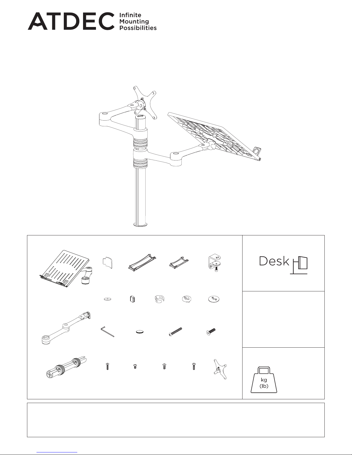
COMPONENT CHECKLIST
A
Notebook tray
assembly
(x1)
E
Primary arm
cable cover
(x1)
F
Secondary arm
cable cover
(x1)
N
Self adhesive
hook & loop
(x4 sets)
B
Monitor
arm
(x1)
C
Pole
assembly
(x1)
D
Rotation
limitor
(x1)
P
Screw
M8 x 30mm
(x1)
K
Pole
top cap
(x1)
L
Bolt through
base
(x1)
M
5mm
Allen key
(x1)
R
Mounting
screws
M4 x 10mm
(x4)
S
Mounting
screws
M4 x 12mm
(x4)
T
Mounting
screws
M4 x 16mm
(x4)
Q
Security
Screw
M4 x 16mm
(x1)
H
Steel
washer
(x1)
I
Cable
stop
(x2)
O
Screw
M8 x 60mm
(x1)
G
Desk clamp
assembly
(x1)
J
Cable
clip
(x1)
U
VESA
head
(x1)
Installation Guide
AF-AT-NBC
Notebook Monitor Arm
Combo Mount
IMPORTANT INFORMATION
! Please ensure this product is installed as per these installation instructions.
! The manufacturer accepts no responsibility for incorrect installation.
REQUIRED TOOLS
WEIGHT RANGE
• Power Drill
• Drill Bit
• Phillips Head Screwdriver
0 - 8kg
(0 - 17.6lbs)
Page 2

AF-AT-NBC Page 2 of 4
1. Desk overview
The desk clamp bracket
can be repositioned to
suit different mounting
surface thicknesses.
1.1 Default 1.2 Inverted
2. How to reconfigure desk clamp
2.1 Remove screws
(M8 x 16mm Countersunk screw)
2.2 Remove clamp plate 2.3 Invert bracket 2.4 Replace clamp plate 2.5 Reattach bracket
Pressure
Plate
M10 Desk
Clamp Screw
5mm Allen
Key
M8 x 30mm
Countersunk
screw Tighten
firmly
3.2 Place in desired location 3.3 Screw pressure plates
in and tighten firmly.
Drill 9mm hole in desired post
position on work surface.
3.1 Attach clamp to post
3. Post mount configuration 4. Bolt through
9mm
(3/8”)
25mm
offset
MIN THICKNESS - 0mm (0”)
MAX THICKNESS - 39mm (1.5”)
MIN THICKNESS - 35mm (1.4”)
MAX THICKNESS - 76mm (3”)
5. Installing bolt through
5.1 Attach plate to post
Align rear hole with
hole on desk
5mm
Allen key
M8x60mm
Screw
Bolt
through
plate
6. Install VESA monitor head
Optional Spacers
(may be required
for recessed and
uneven surfaces)
VESA monitor
head
Screen
M4x10/12/16mm
Phillips head
mounting screws
6.1 Install VESA monitor head as shown.
100mm
100mm
Page 3
AF-AT-NBC Page 3 of 4
1st Handgrip
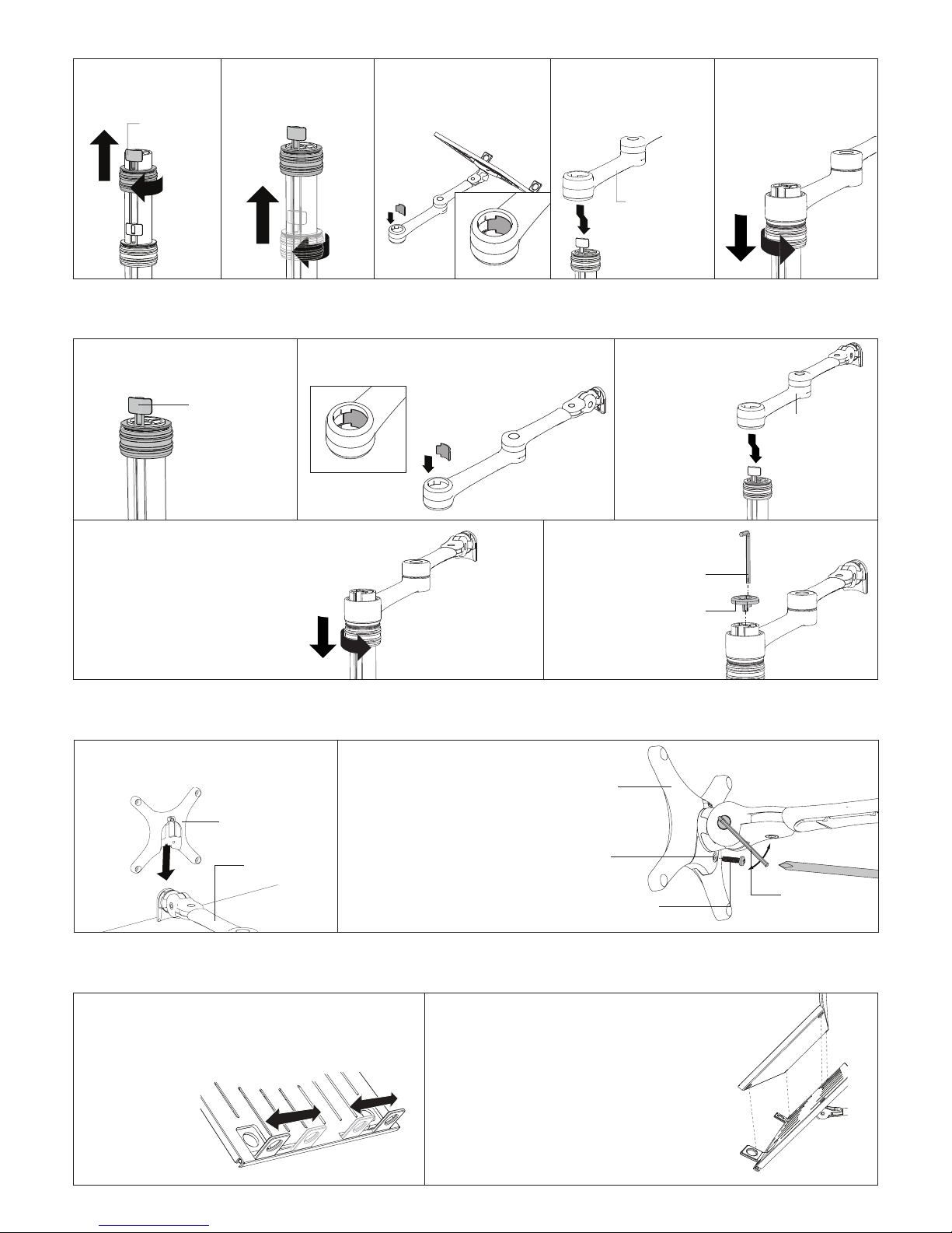
7. Mount Notebook Tray Arm
7.1 Unlock 1st handgrip
and remove from
pole assembly
Notebook Tray
& Arm Assembly
7.2
Unlock 2nd handgrip
and raise so that
handgrip tab protrudes
7.3 OPTIONAL ROTATION
LIMITER Insert rotation
limiter for 180� rotation
around mounting pole
7.4 Slip the notebook
tray & arm assembly
over the handgrip tab
and then onto the pole
7.5 Slide the arm
assembly and handgrip
down the pole before
locking the handgrip at
the desired height
Arm Assembly
8. Install arm assembly
Handgrip
Tab
5mm
Allen key
Pole
top cap
8.1 Reinstall handgrip so that
handgrip tab protrudes
8.4 Slide the arm assembly and
handgrip down the pole before locking
the handgrip at the desired height
8.5 Insert pole
top cap into
pole. This is also
where the allen
key is stored.
8.3 Slip the arm
assembly over the
handgrip tab and
then onto the pole
8.2 OPTIONAL ROTATION LIMITER Insert rotation
limiter for 180� rotation around mounting pole
9. Mounting Monitor
10. Install Notebook
VESA monitor head
Arm assembly
9.2 OPTIONAL SECURITY SCREW
Ensure the monitor is supported,
then loosen the monitor head
screw with the 5mm allen key and
tilt screen up before installing the
m4 x 16mm security screw into the
security screw hole
Note: Support Screen
when adjusting tilt.
9.1 Insert VESA monitor head into the
receptacle in the arm assembly
5mm Allen key
Phillips head
screwdriver
Loosen
Tighten
Security screw
hole
M4 x 16mm
Security screw
Monitor head
screw
10.1 Adjust the support
tabs to suit the width of
the notebook computer
ensuring that cable ports
are not obstructed
10.2 To increase stability, use the self
adhesive Hook-and-Loop Fasteners supplied
• Peel off the backing paper to the fasteners
• Attach fasteners to both the notebook tray
and computer
• Ensure that each set of fasteners are
correctly aligned i.e. Hook to loop
Page 4
AF-AT-NBC Page 4 of 4
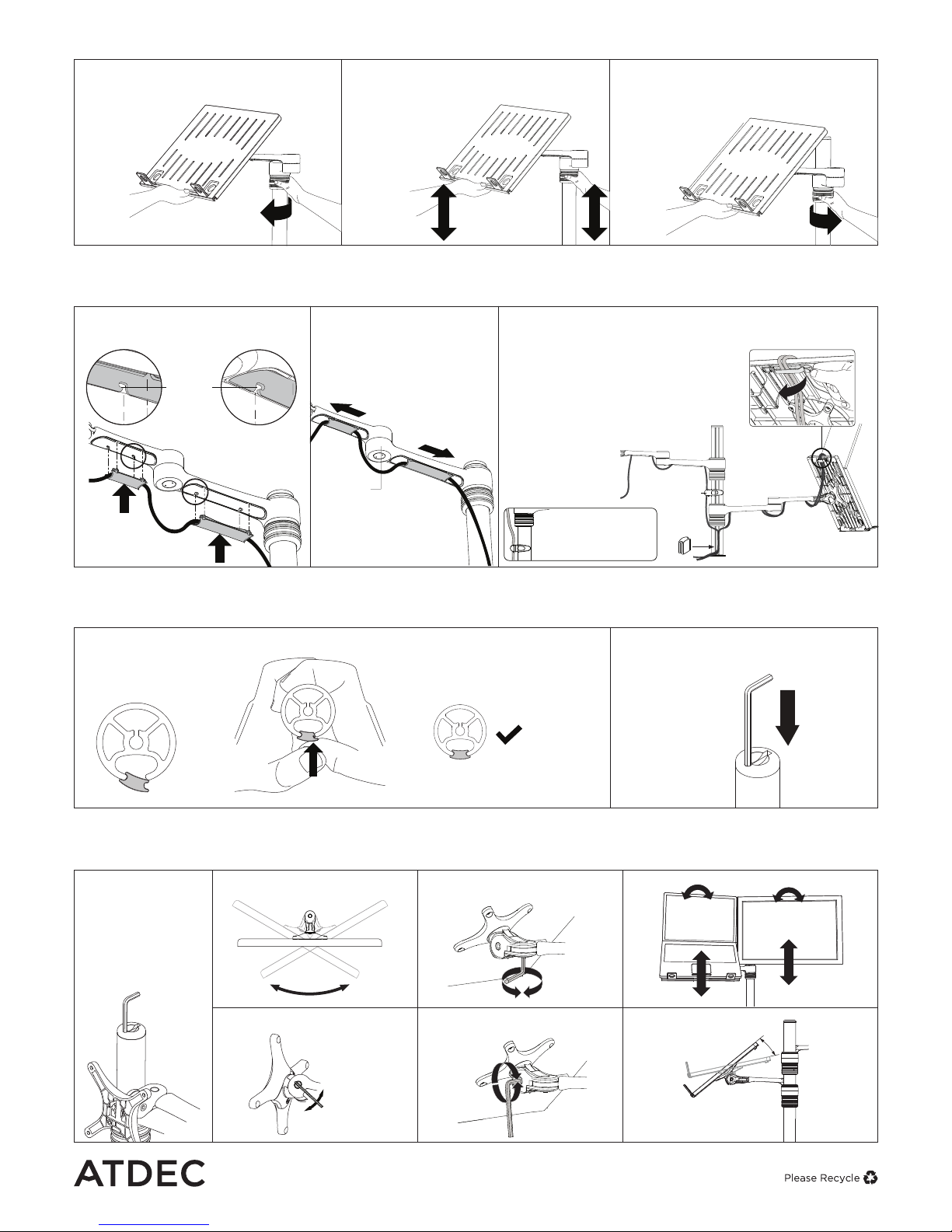
11. Adjust Height
11.1 Unlock handgrip ensuring screen
or notebook tray and arm assembly
are supported
11.2 Lift/lower screen or notebook tray to
the desired height. move both screen and
arm assembly together
11.3 Lock handgrip firmly
LIFT
Cable
Stop
Cable
Clip
Note: If this product is in a
Multi-user environment, use
the supplied cable clip to
secure the cables to the pole.
12.1 After plugging in your cables,
install the cable covers
12.3 Cable clips and cable stops can be installed
to further manage cables. Please see over
Lock Slot
Elbow joint
‘click’
‘click’
12. Cable Management
Note: After connecting the notebook
cables, route them through the cable
management clip on the back of the
notebook tray
Ensure enough cable slack is
given to allow for movement.
Insert cable covers
up into lock slots.
12.2 Push cable covers
away from elbow joint to
secure in place
13. Insert Cable Stops
Note: Press down firmly onto
the other edge of the Cable
Stop and hold. This allows the
rear profile to flex in place
13.1 Insert cable stop on one edge
of the pole slot
13.2 Insert allen key into top cap
on pole
Allen key
storage
Allen Key
Storage
Loosen
Tighten
Loosen
Tighten
Loosen
Tighten
Horizontal
Adjustment
±95°
Portrait/Landscape
Rotation
±5°
±25° Tilt
14. Adjusting the display bracket
Adjust the tilt
angle of the
notebook tray as
desired, locking it
in position using
the 5mm allen key
TILT (tray angle up/down)
TILT (screen angle up/down)
PAN (tray angle left/right)PAN (screen angle left/right)
5mm Allen Key
Tighten
Loosen
atdec.com | atdec.co.uk | atdec.com.au
No portion of this document or any artwork contained herein should be reproduced in any way without
the express written consent of Atdec Pty Ltd. Due to continuing product development, the manufacturer
reserves the right to alter specifications without notice. ©20180319A
 Loading...