

Page 1
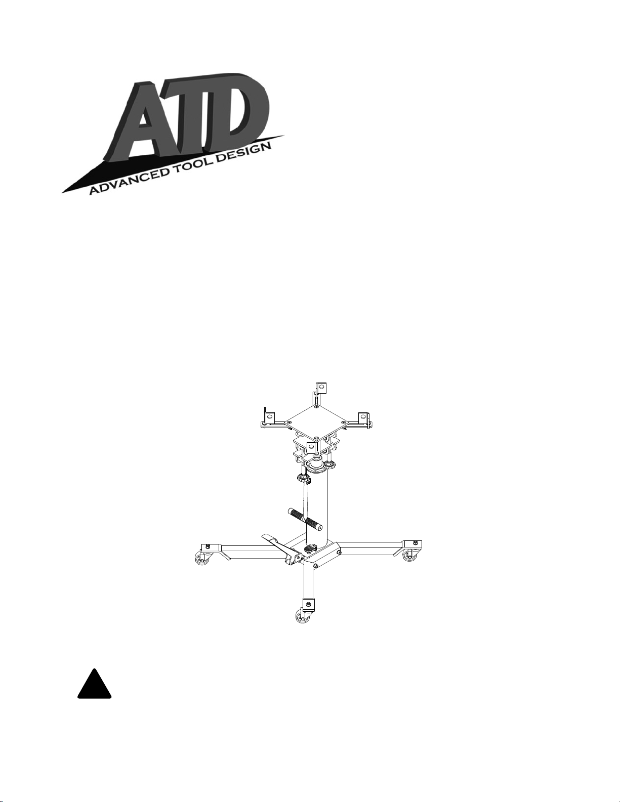
Telescopic
Transmission
Jack
Operating Instructions & Parts Manual
Model Number
Atd-7432
Capacity
1000 Lb.
This is the safety alert symbol. It is used to alert you to potential personal injury hazards.
!
Obey all safety messages that follow this symbol to avoid possible injury or death.
Atd Tools Inc.
160 Enterprise Drive, Wentzville MO 63385
ATD7432-M0 10/07
Printed in China
Page 2
SAFETY and GENERAL INFORMATION
Save these instructions. For your safety, read, understand, and follow the information provided with and on this jack.
The owner and operator shall have an understanding of this jack and safe operating procedures before attempting
to use. The owner and operator shall be aware that use and repair of this product may require special skills and
knowledge. Instructions and safety information shall be conveyed in the operator’s native language before use of this
jack is authorized. If any doubt exists as to the safe and proper use of this jack, remove from service immediately.
Inspect before each use. Do not use if broken, bent, cracked, or damaged parts (including labels) are noted. Any
jack that appears damaged in any way, operates abnormally or is missing parts, shall be removed from service
immediately. If the jack has been or suspected to have been subjected to a shock load (a load dropped suddenly,
unexpectedly upon it), immediately discontinue use until jack has been checked by an Atd Tools authorized service
center (
inspection be done by qualified personnel. Replace worn or damaged parts and assemblies with Atd Tools Authorized
Replacement Parts only. Labels and Operator’s Manuals are available from manufacturer.
contact distributor or manufacturer for list of Authorized Service Centers)
. It is recommended that an annual
PRODUCT DESCRIPTION
Atd Tools Hydraulic Transmission Jack is designed to be used as an aid in the removal and installation of automotive
and light truck transmissions, transfer cases and transaxles. It is intended for use under an overhead lift or in a
garage pit.
Do not use for any purpose other than those uses outlined above.
!
SPECIFICATIONS
Model Capacity
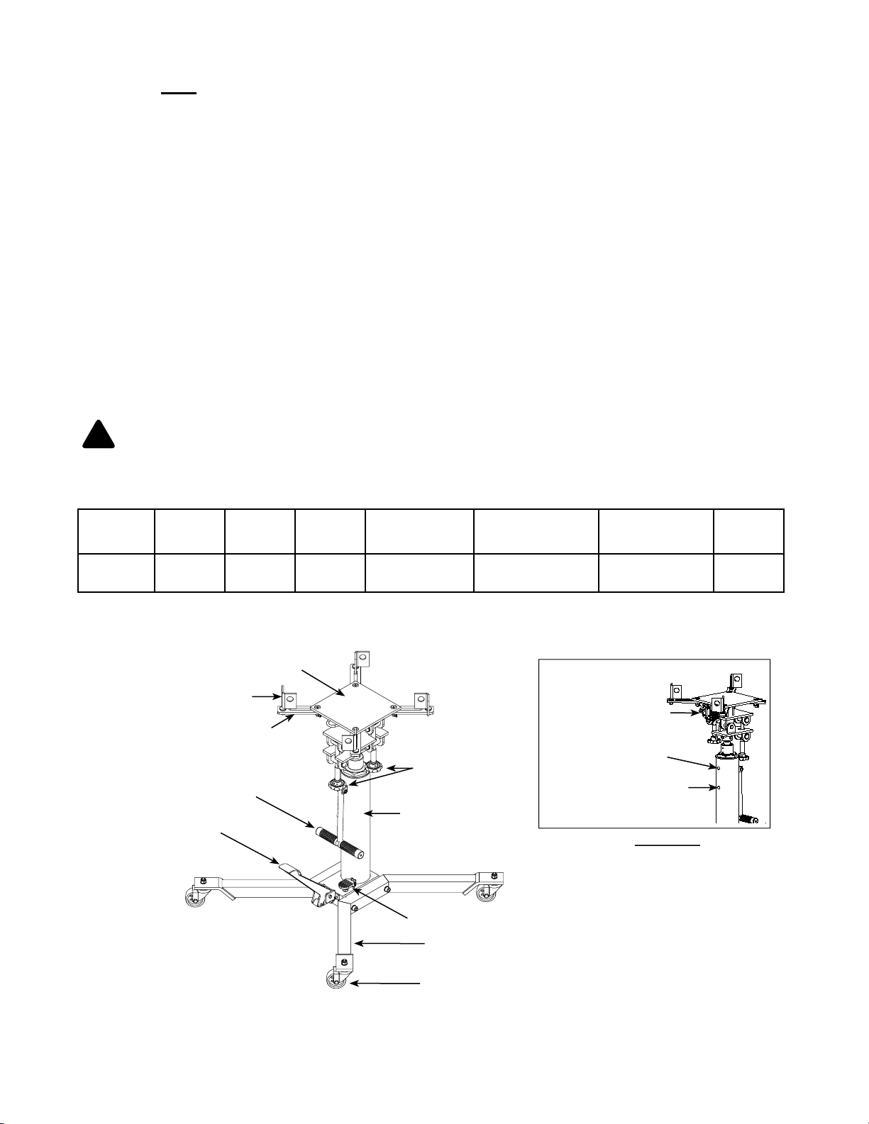
Atd-7432 1000-lb 36" 73" 9 7/8" x 9 7/8" 18 1/2" x 18 1/2"
Saddle Bracket
Bracket Bar
Position Handle
Lift Pedal
Min.
Height
Saddle Base
Max.
Height
Saddle Base
Tilt Adjustment
Knobs
Hydraulic Unit
Release Valve Pedal
Extended Saddle
Area
*Shipping/Vent Plug
*replace w/ vent plug
before initial use
Jack Size
(L x W)
34 1/2" x 34 3/8"
Nylon Strap
Oil Filler Plug
Rear View
Net
Weight
141 lb.
Base half
Caster
Figure 1 - Transmission Jack Components
2
Page 3
ASSEMBLY (Refer to Figure 1)
Estimated Assembly Time:
20 minutes.
Tools Required for Assembly:
A big Philips Screwdriver, 19mm wrench, socket
wrench and torque wrench.
1. Package contents:
(a) Hydraulic unit,
(b) Saddle unit,
(c) Base half 2 pieces,
(d) Caster 4 pieces,
(e) Saddle bracket & bracket bar 4 sets,
(f) Position handle, and
(g) hardware
2. Attach all four casters to the base halves and secure
with washers and M12 locknuts.
3. Attach either one of the two base halves to the base
of the hydraulic unit, then secure using M12x70 bolts
and lock washers. Apply the same procedure to the
other base half. Use torque wrench to tighten to 30
lb.ft.. Do not overtighten.
4. Attach the position handle onto Hydraulic unit with
M10x40 bolt and locknut.
5. Position the saddle unit above the ram plunger, place
the saddle socket onto the ram plunger. Secure with
two M12x20 bolts provided.
6. Secure all four bracket bars to the saddle with
M12x40 screws and wing nuts. Then attach saddle
brackets onto the bracket bars with M10 nuts.
BEFORE USE
1. Verify that the product and the application are
compatible, if in doubt call Atd Tools Technical
Service (636)327-9050.
2. Before using this product, read the operator's manual
completely and familiarize yourself thoroughly with
the product, its components and recognize the
potential hazards associated with its use.
3. Press the release valve pedal, ensure that saddle is
fully lowered. Remove shipping plug (shipping plug
is located above the oil filler plug). Ensure oil level
is just below the rim of the oil filler hole. Reinstall
with vent plug provided.
4. Check to ensure that jack rolls freely, that the pump
and release valve operate smoothly. Raise and lower
the unloaded jack throughout the advertised lift range
before putting into service.
5. Replace worn or damaged parts and assemblies
with Factory Authorized Replacement Parts only.
Lubricate as instructed in Maintenance Section.
! WARNING
• Study, understand, and follow all printed materials
provided with/on this product before use.
• Do not exceed rated capacity.
• Use only on hard, level surface.
• Use of this jack is limited to the removal,
installation and transportation of transmissions,
transfer cases and transaxles. Do not use a
transmission jack to tilt or support a vehicle.
• Use only the saddle assembly to lift. Never use
any other part of the jack as a lifting surface.
• Ensure the center gravity of load is centered on
the saddle.
• For your safety, do not exceed 10 degree tilt angle
of the saddle assembly in all directions.
• Adequately support the vehicle before servicing.
• Use only strap, attachments and/or adapters
supplied by the manufacturer.
• If loaded jack must be moved, make sure that the
load is secured, stable and in lowest position.
• This is a lifting device only.
• Transfer load immediately to appropriate support
device for service or repair.
• Shock loads may cause the sudden loss of load
and/ or cause the jack to tip or flip over violently,
bend or break.
• No alterations shall be made on this product.
• Failure to heed these markings may result in
personal injury and/or property damage.
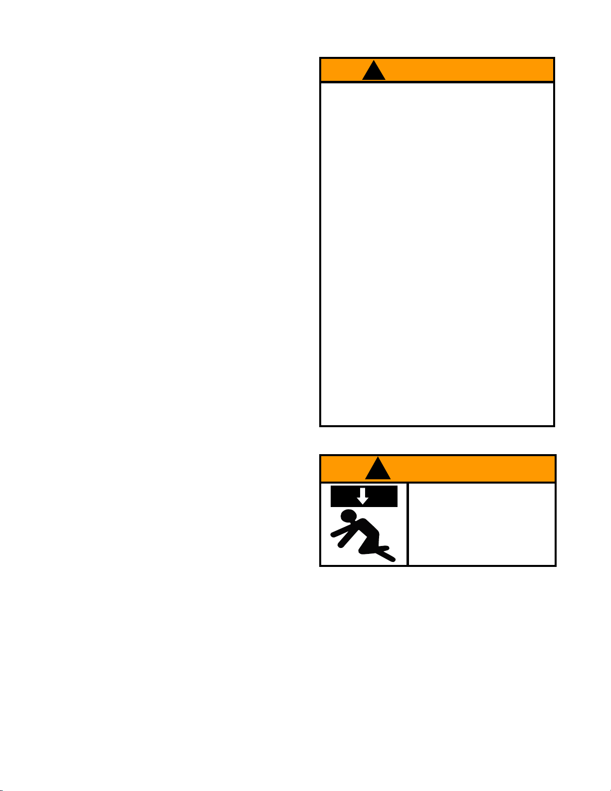
! WARNING
To avoid crushing and related
injuries:
NEVER work on, under or
around a load supported
only by transmission jack.
Immediately transfer the load to
an appropriate support device.
3
Page 4

OPERATION
Ensure the transmission is centered on the
!
jack.
jack to tip over resulting in personal injury or property
damage. For your safety, do not exceed 10 degree tilt
angle of the saddle assembly in all directions.
Keep safety strap secured.
!
and personnel are clear before
Raise saddle:
1. Pump lift pedal until saddle reaches desired
position.
2. Fol low vehicle man ufact urers recommended
procedures for removing the load as outlined in
vehicle service manual or repair guide.
3. Secure load with nylon strap.
4. Ensure load’s center of gravity is centered on the
saddle, load is stable and in lowest position before
moving jack.
Lower saddle:
1. Slowly, gently apply downward pressure to the release
valve pedal until the load is completely lowered.
2. Immediately transfer the load to an appropriate repair
fixture.
An off-center transmission could cause the
Be sure all tools
lowering load.
MAINTENANCE
Important: Use only good grade hydraulic jack oil. Avoid
mixing different types of fluid and NEVER use brake
fluid, turbine oil, transmission fluid, motor oil or glycerin.
Improper fluid can cause premature failure of the jack
and the potential for sudden and immediate loss of load.
Mobil DTE 13M or equivalent recommended.
Adding oil
1. With saddle fully lowered, set jack in its upright, level
position. Remove oil filler plug.
2. Fill until oil is level with the filler plug hole, reinstall
oil filler plug.
Changing oil
For best performance and longest life, replace the
complete fluid supply at least once per year.
1. With saddle fully lowered, set jack in its upright, level
position. Remove the oil filler plug.
2. Lay the jack on its side and drain the fluid into a
suitable container.
Note. Dispose of hydraulic fluid in accordance with
local regulations.
3. Set jack in its level, upright position and fill with oil
until just below the rim of the oil filler hole. Reinstall
the oil filler plug.
Lubrication
A periodic coating of light lubricating oil to pivot points,
axles and hinges will help to prevent rust and assure
that wheels, casters and pump assemblies move
freely.
Cleaning
Periodically check the pump piston and ram for signs
of rust or corrosion. Clean as needed and wipe with
an oily cloth.
Note: Never use sandpaper or abrasive material on
these surfaces!
Storage
When not in use, store the jack with saddle in lowest
position.
4
Page 5
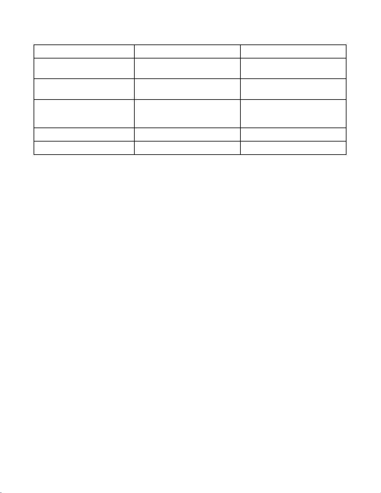
TROUBLESHOOTING
Symptom Possible Causes Corrective Action
Jack will not lift load • Overload condition
• Hydraulic unit malfunction
Jack will lift, but not maintain
pressure
Jack will not lower after unloading • Reservoir overfilled
Poor lift performance • Fluid level low • Ensure proper fluid level
Jack will not lift to full extension • Fluid level low • Ensure proper fluid level
• Overload condition
• Hydraulic unit malfunction
• Linkage binding
• Remedy overload condition
• Contact Atd Tools Tech. Service
• Remedy overload condition
• Contact Atd Tools Tech. Service
• Ensure load is removed, then drain
fluid to proper level
• Clean and lubricate moving parts
5
Page 6
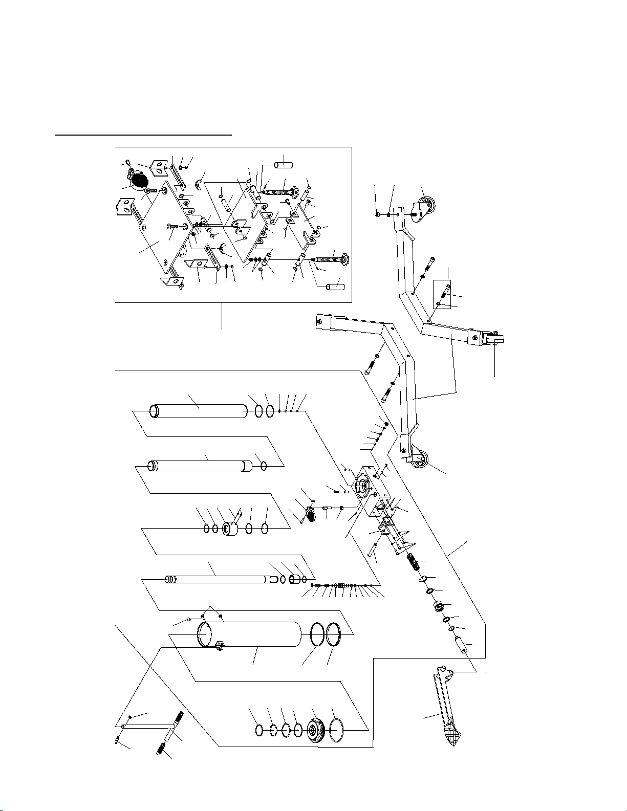
REPLACEMENT PARTS
1
2
3
4
5
4
6
7
8
9
11
10
12
13
13
14
14
14
15
16
17
18
19
20
21
21
22
23
24
25
26
27
14
28
29
30
31
32
33
34
35
36
37
38
39
40
41
42
43
44
45
46
47a
48
49
50
51
52
53
54
55
56
57
58
59
60
61
62
63
646566
67
47b
69
70
72
73
74
75
74
76
77
78
79
80
81
82
83
84
85
85
85
85
85
85
85
85
86
86
87
88
88
88
89
90
89
90
90
90
83
84
82
91
91
92
93
93
94
94
93
93
95
96
97
96
97
95
98
98
99
100
99
101
68
102
Not all components of the jack are replacement items, but are illustrated as a convenient reference of location and
position in the assembly sequence. When ordering parts, give Model number, part number and description below.
Call or write for current pricing: Atd Tools Inc. 160 Enterprise Drive, Wentzville, MO 63385. Tel:(636)327-9050
Fax:(636)327-9044
Replacement Parts for Model Atd-7432
6
Page 7
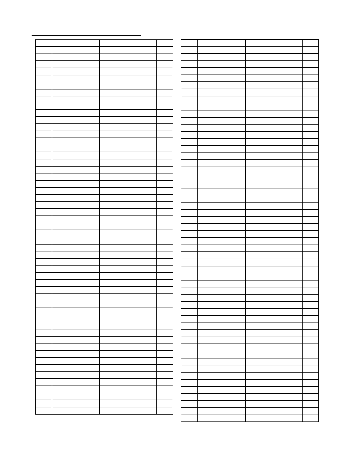
Replacement Parts List for Model Atd-7432
Item Part No. Description Qty
1 G390-10000-000 Hydraulic Unit 1
2 G390-15001-000 Pump Piston 1
3 N/A Retaining Ring 1
4 * U-cup 2
5 G390-15002-000 Pump Piston Guide 1
6 * O-ring 1
7 G390-10004-000 Spring 1
8 5105-06020-000 Socket Head Screw,
M6x20
9 N/A Lock Washer 3
10 5405-12070-000 Pin 1
11 5405-02028-000 Retaining Pin 1
12 G390-16000-000 Pedal Bracket 1
13 N/A Set Screw 2
14 5601-00635-000 Steel Ball 5
15 N/A Steel Ball 1
16 N/A Spring Cap 1
17 N/A Safety Spring 1
18 N/A Screw 1
19 * O-ring 1
20 N/A Bolt Plug 1
21 N/A Collar 2
22 G251-20008-000 Filter 1
23 5202-00010-000 Nut, M10 1
24 G390-10006-000 Spindle 1
25 5405-02018-000 Retaining Pin 1
26 G390-10005-000 Release Pedal 1
27 5405-07027-000 Pin 1
28 G390-10008-000 Spring 1
29 5601-00952-000 Steel Ball 1
30 5309-00012-000 Washer 1
31 * Back-up Washer 1
32 * O-ring 1
33 N/A Cylinder 1
34 N/A C-clip 1
35 N/A Ram 1
36 * Back-up Washer 1
37 * O-ring 1
38 N/A Set Screw 2
39 N/A Steel Ball 1
40 N/A Ram Nut 1
41 * O-ring 1
42 * Back-up Washer 1
43 N/A C-clip 1
44 N/A Ram Plunger Guider 1
45 N/A C-clip 1
46 N/A Ram Plunger 1
47a 5905-00100-100 Plug, Rubber 2
47b 5905-00100-001 Vent Plug 1
48 N/A Reservoir 1
49 * Back-up Washer 1
50 * Seal 1
3
Item Part No. Description Qty
51 * O-ring 1
52 N/A Top Nut 1
53 * Back-up Washer 1
54 * O-ring 1
55 * O-ring 1
56 * Back-up Washer 1
57 5309-00008-000 Washer 1
58 G390-17001-000 Throttle 1
59 G390-17002-000 Spring 1
60 5601-00476-000 Steel Ball 1
61 * O-ring 1
62 * Back-up Washer 1
63 G150-04301-000 Releave Valve Nut 1
64 * O-ring 1
65 * O-ring 1
66 G150-04002-000 Spring 1
67 G150-04001-000 Release Valve 1
68 5305-00009-000 E-clip 1
69 N/A Capscrew, M10x40 1
70 N/A Locknut, M10 1
71 G251-00007-000 Handle Grip 2
72 G390-20000-000 Handle 1
73 G390-30000-000 Foot Pedal 1
74 T250-05000-000 Caster 2
75 T250-01000-000 Base Half 2
76 5103-12070-000 Capscrew, M12x70 4
77 5303-00012-000 Lock Washer 4
78 G390-50000-000 Caster w/Break 2
79 5307-00012-000 Washer 4
80 5206-00012-000 Locknut, M12 4
81 G390-40000-000 Saddle Assembly 1
82 T250-00007-000 Bushing 2
83 T250-08000-000 Screw Assembly 2
84 N/A Spring Pin 2
85 N/A Washer 8
86 N/A Spindle 2
87 N/A Connect Board 1
88 5102-10016-000 Capscrew, M10x16 3
89 N/A Pin 2
90 N/A Washer 4
91 N/A Spindle 2
92 N/A Adjust Board 1
93 N/A Washer 8
94 N/A Nut, M10 2
95 5202-00010-000 Nut, M10 4
96 T250-00006-000 Bracket Bar 4
97 T250-04000-000 Bracket 4
98 5207-00012-000 Wing Nut, M12 4
99 5107-12040-000 Philips Screw, M12x40 4
100 G390-42000-000 Saddle Plate 1
101 G390-41000-000 Nylon Strap Assy. 1
102 G390-90009-K01 Capscrew Kit (4 sets) (*) G3900S-103 Repair Kit 1
7
Page 8

ONE YEAR LIMITED WARRANTY
For a period of one (1) year from date of purchase, ATD Tools Inc. will repair or replace, at its option, without
charge, any of its products which fails due to a defect in material or workmanship under normal usage. This limited
warranty is a consumer's exclusive remedy.
Performance of any obligation under this warranty may be obtained by returning the warranted product,
freight prepaid, to ATD Tools Inc. Warranty Service Department, 160 Enterprise Drive, Wentzville, MO 63385.
Except where such limitations and exclusions are specifically prohibited by applicable law, (1) THE
CONSUMER'S SOLE AND EXCLUSIVE REMEDY SHALL BE THE REPAIR OR REPLACEMENT OF DEFECTIVE
PRODUCTS AS DESCRIBED ABOVE. (2) ATD Tools Inc. SHALL NOT BE LIABLE FOR ANY CONSEQUENTIAL
OR INCIDENTAL DAMAGE OR LOSS WHATSOEVER. (3) ANY IMPLIED WARRANTIES, INCLUDING WITHOUT
LIMITATION THE IMPLIED WARRANTIES OF MERCHANTABILITY AND FITNESS FOR A PARTICULAR
PURPOSE, SHALL BE LIMITED TO ONE YEAR, OTHERWISE THE REPAIR, REPLACEMENT OR REFUND AS
PROVIDED UNDER THIS EXPRESS LIMITED WARRANTY IS THE EXCLUSIVE REMEDY OF THE CONSUMER,
AND IS PROVIDED IN LIEU OF ALL OTHER WARRANTIES, EXPRESS OR IMPLIED. (4) ANY MODIFICATION,
ALTERATION, ABUSE, UNAUTHORIZED SERVICE OR ORNAMENTAL DESIGN VOIDS THIS WARRANTY AND
IS NOT COVERED BY THIS WARRANTY.
Some states do not allow limitations on how long an implied warranty lasts, so the above limitation may not
apply to you. Some states do not allow the exclusion or limitation of incidental or consequential damages, so the
above limitation or exclusion may not apply to you. This warranty gives you specific legal rights, and you may also
have other rights which vary from state to state.
Atd Tools Inc.
160 Enterprise Drive,
Wentzville MO 63385
636-327-9050
8
 Loading...