

Page 1
0712
Page 2

READ ALL INSTRUCTIONS
BEFORE OPERATING
SAVE THESE INSTRUCTIONS
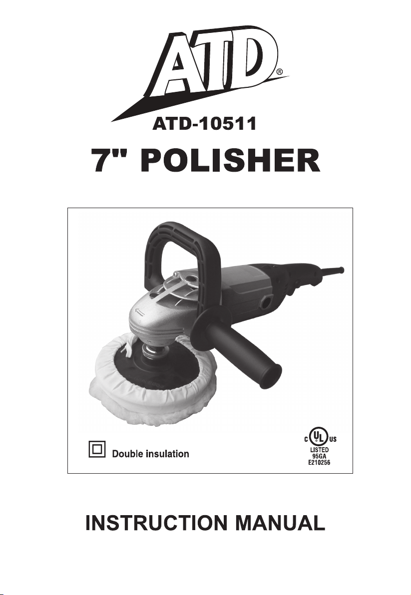
Thank you for purchasing 7" Polisher.
Before attempting to operate your new
Polisher please read these instructions
thoroughly. You will need these
instructions for the safety warnings,
precautions, assembly, operation,
maintenance procedures, parts list and
diagrams. Keep the instructions and
invoice in a safe, dry place for future
reference.
WARNING: When using electric
tools, machines or equipment,
baseic safety precautions
should always be followed to
reduce the risk of fire, electric
shock, and personal injury. The
warnings, cautions and instructions
discussed in this instruction manual
cannot cover all possible conditions or
situations that could occur. It must be
understood by the operator that common
sense and caution are factors which
cannot be built into this product, but
must be supplied by the operator.
SPECIFICATIONS
Motor………….. 120V ~ 60Hz 11Amp
No Load Speed
Weight
……………………………7 lbs
Spindle Thread
Spindle Lock
Trigger Lock………………………Yes
…….1000 - 3000 RPM
……………… 5/8" - 11
………………………Yes
SAFETY RULES
1. Know your machine. Read this
manual carefully. Learn the
machine’s applications and
limitations, as well as specific
potential hazards peculiar to it.
2. Ground all machines. This machine
is “Double Insulated,” meaning that
all outside metal parts are insulated
from electrical power. Double
Insulated tools are equipped with a
polarized plug. This plug will fit in a
polarized outlet only one way. If the
plug does not fit fully in the outlet,
reverse the plug. If it still does not
fit, contact a qualified electrician to
install a polarized outlet. Do not
attempt to circumvent this safety
feature.
3. Do not expose tool to moisture.
Don’t use this machinery in damp
or wet locations. Keep out of rain.
4. Keep work area clean. Cluttered
areas invite injuries.
5. Keep children away. All children
should be kept away from the work
area. Never let a child handle a
tool without strict adult supervision.
6. Do not operate this tool if under
the influence of alcohol or drugs.
Read warning labels on
prescriptions to determine if your
judgment or reflexes are impaired
while taking drugs. If there is any
doubt, do not attempt to operate.
7. Use safety equipment. Eye
protection should be worn at all
times when operating this machine.
Use ANSI approved safety glasses.
Everyday eyeglasses only have
impact resistance lenses. They are
NOT safety glasses. Dust mask,
respirator
hard hat, or hearing protection
must be used in appropriate
conditions.
, non-skid safety shoes,
1
Page 3

8. Wear proper apparel. Loose clothing,
gloves, neckties, rings, bracelets, or
other jewelry may present a potential
hazard when operating this machine.
Please keep all apparel clear of the
machine.
9. Don’t overreach. Keep proper footing
and balance at all times when
operating this product.
10. Always disconnect the machine from
the power supply before servicing or
changing accessories.
11. Check for damage. Check your tool
regularly. If part of the tool is damaged
it should be carefully inspected to
make sure that it can perform its’
intended function correctly. If in doubt,
the part should be repaired. Refer all
servicing to a qualified technician.
Consult your dealer for advice.
12. Keep away from flammables. Do not
attempt to operate this tool near
flammables or combustibles. Failure to
comply may cause serious injury or
death.
13. Do not start tool while it is resting on
materials. Always turn tool on
BEFORE coming in contact with
material surface.
14. Do not set tool down until it has come
to a complete stop.
15. Always check to make sure that trigger
lock is not engaged before plugging
tool in.
16. Keep hands clear of cutting edges and
all moving parts.
17. Protect others in work area from
debris such as chips and sparks.
Provide barriers and shields as needed.
18. Secure work. Use a clamp, vise or
other practical means to hold your
work securely, freeing both hands to
control the tool.
19. Use the right tool for the job. Do not
use a tool or attachment to do a job
for which it was not intended. Do not
alter a tool.
20. Use proper accessories. Using
accessories no recommended may be
hazardous. Be sure accessories are
properly installed and maintained. Do
not defeat a guard or othe safety
device when installing an accessory or
attachment.
21. Remove all adjusting keys and
wrenches. Make a habit of checking
that adjusting keys, wrenches, etc. are
removed from the tool before turning
it on.
22. Guard against electric shock. Prevent
body contact with grounded surfaces
such as pipes, radiators, ranges, and
refrigerators. Hold your tool by
insulated, non-metal grasping surfaces.
Use a Ground Fault Circuit Interrupter
(GFCI) to reduce shock hazards.
23. Avoid accidental starting. Be sure your
tool is turned off before plugging it in.
Do not use a tool if the power switch
does not turn the tool on and off. Do
not carry a plugged-in tool with your
finger on the switch.
24. Do not force tool. Your tool will perform
better at the rate for which it was
designed. Excessive force only causes
operator fatigue, increased wear and
reduced control.
25. Do not abuse cord. Never carry your
tool by its cord or unplug it by pulling
the cord from the outlet. Pull the plug
rather than the cord to reduce the risk
of damage. Keep the cord away
from heat, oil, sharp objects, cutting
edges and moving parts.
26. Maintain tools carefully. Keep handles
dry, clean and free from oil and
grease.Periodically inspect tool cords
and extension cords for damage.
Refer all service to a qualified technician.
27. Store idle tools. When not in use,
store your tool in a dry, secure place.
Keep out of reach of children.
2
Page 4

SERVICE
1. Tool service must be performed only
by qualified repair personnel. Service
or maintenance performed by
unqualified personnel could result in a
risk of injury.
2. When servicing a tool, use only
identical replacement parts. Follow
instructions in the Maintenance section
of this manual. Use of unauthorized
parts or failure to follow Maintenance
instructions may create a risk of electric
shock or injury.
SPECIFIC SAFETY
RULES
1. Accessories must be rated for at least
the speed recommended on the tool
warning label. Wheels and other
accessories running over rated speed
can fly apart and cause injury.
2. Hold tool by insulated gripping surfaces
when performing an operation where
the polishing tool may contact hidden
wiring or its own cord. Contact with a
“live” wire will make exposed metal
parts of the tool “live” and shock the
operator.
GETTING STARTED
Before operating your ATD-10511 7"
Variable Speed Polisher, please check
the contents of the box to make sure you
have everything you will need.
ACCESSORIES:
Straight Auxiliary handle 1 pc
D-shape Auxiliary handle 1 pc
Spanner
Carbon Brush
Hex key wrench
Rubber pad
Velcro pad
Wool bonnet 1 pc
1 pc
1set
1 pc
1 pc
1 pc
ASSEMBLY
1. Choose the most comfortable position
for your side mount handle. Screw the
handle securely into one of the two
handle ports located at the base of the
gear housing.
2. Make sure tool is unplugged and lay it
on its back with the spindle upright.
3. Line up the notches on the inner ring
of the rubber backing pad with the
notches on the spindle. Securely slide
rubber backing pad on to spindle.
4. Hand tighten spindle nut on to spindle
threading.
5. Push in spindle lock button (located
on the back side of the metal gear
housing) and simultaneously tighten
spindle nut with spanner wrench. Be
sure to tighten nut securely.
6. After securing spindle nut, stretch
polishing bonnet over the face of the
rubber backing pad so that the bonnet
wraps around the back of the pad.
7. Pull the fit adjusting string on the
inside lip of the bonnet taut until all
slack is removed and bonnet is snug
against backing pad.
8. Tuck the fit adjusting string back
inside bonnet so it will not interfere
with bonnet surface during polishing.
You are now ready to begin operation of
your Polisher.
3
Page 5
OPERATING YOUR
POLISHER
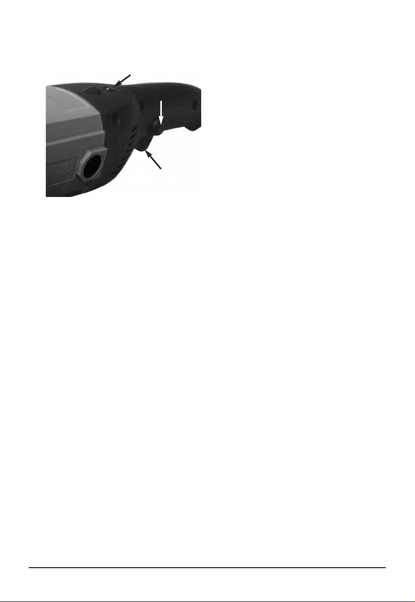
Speed Control Dial
7. When finished release trigger switch.
Remember to let the polisher come to
a complete stop before resting tool on
any surface.
Lock On Switch
Trigger
1. Plug Polisher into standard 110/120
Volt wall socket.
2. Prior to contact with material surface,
pull trigger switch to ON position.
3. Evenly and carefully, lower polishing
bonnet surface to material surface. Do
not apply excessive pressure. Forcing
the polisher down against your work
surface puts unnecessary strain on
the motor and will likely produce
undesirable results in workmanship.
4. This Polisher features a speed control
dial, which controls the polisher’s
maximum rotations per minute. The
speed will remain at the chosen dial
setting by use of the trigger switch.
Dial settings range from 1 to 6. Lower
numbers correspond to lower speeds
and higher numbers correspond to
higher speeds. Generally, lower
speeds are recommended for tight
work areas and higher speeds are
ideal for large surface areas. Use the
setting which best suits your job.
5. To control the speed, set the dial to the
desired number and pull the trigger.
6. For extended work loads the Polisher
is equipped with a “lock ON” switch.
With trigger switch engaged, press
lock switch with thumb. To release
lock switch, press the trigger switch
again.
MAINTENANCE
Keep your tool in good condition by
adopting a regular maintenance program.
Before use, examine the general condition
of your tool. Inspect guards, switches, tool
cord and extension cord for damage.
Check for loose screws, misalignment,
binding of moving parts, improper mounting,
broken parts, and any other condition that
may affect its’ safe operation. If abnormal
noise or vibration occurs, turn the tool off
immediately and have the problem
corrected before further use. Do not use a
damaged tool.
WARNING: To reduce the risk of injury,
always unplug your tool before performing
any maintenance. Never disassemble the
tool or try to do any rewiring on the tool’s
electrical system.
CLEANING
Clean dust and debris from vents. Keep
the tool handles clean, dry and free of oil
or grease. Use only mild soap and damp
cloth to clean your tool since certain
cleaning agents and solvents are harmful
to plastics and other insulated parts.
Some of these harmful solvents include:
gasoline, turpentine, lacquer thinner, paint
thinner, chlorinated cleaning solvents,
ammonia, and household detergents
containing ammonia. Never use flammable
or combustible solvents around tools.
WARNING: To reduce the risk of injury,
electric shock and damage to the tool,
never immerse your tool in liquid or allow
liquid to flow inside the tool.
4
Page 6
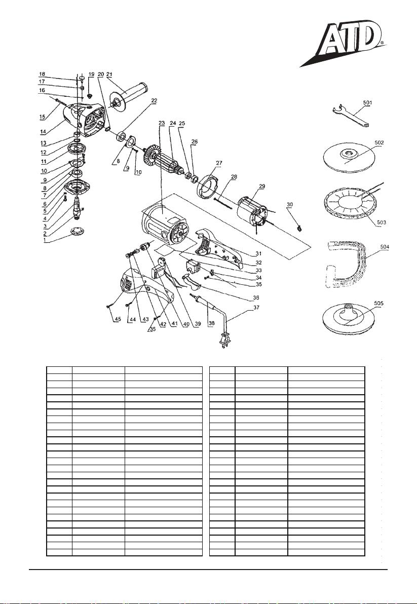
PARTS LIST AND DIAGRAM
ATD-10511
ITEM# ORDERING PART# P ART DESCRIPTION ITEM# ORDERING PART# P ART DESCRIPTION
PRT10511-01 FLANGE NUT
1
2
PRT10511-02 KEY 4x5x13
PRT10511-03 SPINDLE
3
4
PRT10511-04 SCREW M5x16
5
PRT10511-05 SPRING WASHER 5
6
PRT10511-06 BEARING HOUSING
7
PRT10511-07 BEARING 6002.2Z
8
PRT10511-08 BEARING COVER
9
PRT10511-09 SPRING WASHER 4
10
PRT10511-10 SCREW M4x10
11
PRT10511-11 BIG GEAR
12
PRT10511-12 CIRCLIP FOR SHAFT
13
PRT10511-13 BRONZE BUSHING
14
PRT10511-14 GEAR BOX
15
PRT10511-15 SCREW ST5x45
PRT10511-16 E-RING 6
16
17
PRT10511-17 SPRING
18
PRT10511-18 BRAKE PIN
19
PRT10511-19 RUBBER PLUNGE
20
PRT10511-20 CIRCLIP FOR SHAFT
21
PRT10511-21 SIDE HANDLE
22
PRT10511-22 BEARING 6201.2Z
23
PRT10511-23 PLASTIC HOUSING
24
PRT10511-24 ARMATURE
25
PRT10511-25 BEARING 608.2Z
26
PRT10511-26 RUBBER BUSHING
27
PRT10511-27 GUIDE WIND CIRCLE
28
PRT10511-28 SCREW ST4.2x75
PRT10511-29 STATOR
29
30
PRT10511-30 TERMINAL
31
PRT10511-31 BLACK HANDLE (A)
32
PRT10511-32 NAMEPLATE
33
PRT10511-33 SWITCH
34
PRT10511-34 CORD CLIP
35
PRT10511-35 SCREW ST4.2x14
36
PRT10511-36 SWITCH PUSH BUTTON
37
PRT10511-37 CORD
38
PRT10511-38 RUBBER SLEEVE
39
PRT10511-39 TIMING SWITCH
40
PRT10511-40-43 BRUSH HOLDER W/CAP (PAIR)
41
PRT10511-41 BLACK HANDLE (B)
PRT10511-42 CARBON BRUSH (PAIR)
42
43
PRT10511-43 USE PRT10511-40-43
44
PRT10511-44 SCREW ST 4.2x18
45
PRT10511-45 SCREW ST 4.2x22
501
PRT10511-501 SPANNER
502
PRT10511-502 RUBBER PAD
503
PRT10511-503 WOOL BONNET
504
PRT10511-504 D SHAPE HANDLE
505
PRT10511-505 VELCRO PAD
PRT10511-PAD RETROFIT KIT
01, 501, 502
5
Page 7
Page 8
RPM's equivalents for indicator
Please note there is 5% - 10% tolerance on each ng.
S
ng 1.: 1062 RPM
ng 2.: 1842 RPM
S
ng 3.: 1922 RPM
S
S
ng 4.: 2331 RPM
ng 5.: 2573 RPM
S
ng 6.: 2988 RPM
S
 Loading...