

Page 1

ACOUSTIC
ENGINEERS
AT C Electronics
User Operating Manual
Page 2

Electronics
1. Read instructions – all the safety and operating instructions should
be read before the appliance is operated.
2. Retain these instructions – the safety and operating instructions
should be retained for future reference.
3. Heed warnings – all warnings on the appliance and in the operating
instructions should be adhered to.
4. Follow instructions – all operating and other instructions should be
followed.
5. Water and moisture – the appliance should not be used near water,
for example near a bathtub, washbowl, kitchen sink, laundry tub, in
a wet basement or near a swimming pool etc..
6. Ventilation – the appliance should be situated so that its location or
position does not interfere with its proper ventilation. For example,
the appliance should not be situated on a bed, sofa, rug or similar
surface that may block the ventilation openings. Similarly, the
appliance should not be built into an installation, such as a bookcase
or cabinet, that may impede the flow of air through the ventilation
openings.
7. Heat – the appliance should be situated away from heat sources such
as radiators, stoves or other appliances that produce heat.
8. Power sources – the appliance should be connected to a power
supply only of the type described in the operating instructions or as
marked on the appliance.
9. Power cord protection – power supply cords should be routed so
that they are not likely to be walked on or pinched by items placed
upon or against them, paying particular attention to cords at
plugs, convenience receptacles and the point where they
exit the appliance.
10. Cleaning – the appliance should be cleaned only as recommended by
the manufacturer.
11. Unattended periods – the power cord of the appliance should
be unplugged from the outlet when left unused for a long period
of time.
12. Object and liquid entry – care should be taken so that objects
and liquids do not fall into the appliance.
13. Damage requiring service – the appliance should be serviced
by qualified service personnel when:
i. the power supply cord or the plug has been damaged
ii.objects have fallen or liquid has been spilled into the appliance
iii. the appliance has been exposed to rain or other serious
liquid
exposure
iv. the appliance does not appear to operate normally or exhibits a
marked change in performance
v. the appliance has been dropped or the cabinet damaged
14. Servicing – the user should not attempt to service the appliance
beyond those measures described in the operating instructions. All
other servicing should be referred to qualified service personnel.
15. Grounding or polarisation – precautions should be taken so that
grounding or polarisation means for the appliance are not defeated.
Safety Warnings
Contents
Page 1 Introduction
Page 1 Generic Information
Section G1 Installation
Section G2 Mains Connection
Page 2 Section G3 Fuses
Section G4 ATC Remote Handset
Section G5 Care and Maintenance
Section G6 Warranty and Contact
Page 3 CA2 Preamplifier
Section 1.1 Description
Section 1.2 Inputs
Page 5 Section 1.3 Outputs
Section 1.4 Operation
Section 1.5 Specifications
Page 7
SCA2 Preamplifier
Section 2.1 Description
Section 2.2 Inputs
Page 9 Section 2.3 Outputs
Page 10 Section 2.4 Operation
Page 11 Section 2.5 Specifications
Page 12 P1 & P2 Power Amplifiers
Section 3.1 Description
Inputs
Outputs
Page 13 Section 3.4
Operation
Page 14 Section 3.5 Specification
Page 15 SIA2-150 Integrated Amplifier
Section 4.1 Description
Section 4.2 Inputs
Section 4.3 Outputs
Page 16 Section 4.4 Operation
Page 17 Section 3.5 Specification
Section 3.2
Page 6
Section 3.3
Page 3

1
1
Electronics
Welcome. In selecting ATC you have chosen an example of the finest
audio engineering available. ATC was founded on a principle of
engineering excellence, and that principle still defines our products
today. Given the right opportunities, ATC products will deliver
exceptional audio performance, but the opportunities will only arise
from careful and thoughtful installation and use. Please read the
following manual fully. It will help you understand the product and to
realise its full potential. We are happy to answer questions and offer
advice on any issues that arise through installation or use of ATC
products. Contact details can be found at the back of this manual.
ATC was founded in London in 1974 by Australian emigre Bill Woodman, who still
heads the company today. An enthusiastic pianist and engineer he was naturally
drawn to loudspeaker design and after a period working at Goodmans, where many
of the names that went on to found British loudspeaker companies began their
careers, he struck out on his own. The premise on which ATC began is a simple one,
and one that in many respects is still true today: hi-fi loudspeakers tend to be detailed
and accurate but of limited dynamic range, while professional monitor speakers tend
to express the opposite character. ATC products were designed from the outset to
offer the best of both. It’s an easy concept to describe, but surprisingly difficult to
engineer.
The difficulty inherent in designing such loudspeakers is one of scale. Hi-fi levels of
accuracy and detail call for lightweight moving parts and delicate engineering.
Professional monitor levels of performance however demand far more robust
components engineered to survive the rigours of high level use for extended periods.
The only way to combine the two is through precision engineering of a class and
scale more often associated with aerospace or motor-sport. But the results are
worth the effort and the cost. ATC loudspeakers, with their unique in-house
designed drivers, combine the best of hi-fi and professional to devastating effect.
ATC has become synonymous with active systems. Choosing to offer active
loudspeakers (where the passive crossover network is replaced by active filters and
multiple power amplifiers) is simply a result of the uncompromising attitude to
loudspeaker design. While passive systems still have their place, and ATC engineering
skills can still bring remarkable results from them, “active” is a fundamentally better
solution to the problems posed by accurate, high level music reproduction. The ATC
instinct is always for the better solution. Not cheaper, not quicker, but better.
It was the development of active loudspeakers that first brought ATC into electronics
design and engineering. Active speakers demand multiple power amplifiers so ATC
from the mid 1980s became not just a loudspeaker manufacturing company but an
electronics manufacturer too. The further step from electronics for active speakers
to a range of stand-alone amplifier products was natural and now means that ATC
engineering is available from the recording desk or CD player output to the ears.
From modest beginnings ATC has grown to become one of the very few
manufacturers successful across both domestic and professional audio. By selecting
ATC you join a group of music lovers, professional audio engineers, studios and
musicians across the World that understand and value the engineering that goes into
an ATC product - and the sound that comes out.
Introduction Generic Information
The information in the following Sections
G1 to G5 is common to all ATC electronics
products. We recommend that you read
this page, and the safety warnings that
proceed it, before continuing to read the
pages dedicated to your specific ATC
products.
G1 Installation
A
TC Equipment has been designed to be free
standing either within an equipment stand or
simply on a convenient item of furniture. There are
no special ventilation requirements (but please see
notes on Amplifiers below). It is recommended that
at least 100mm (4 inches) clearance be left behind
a unit for plugs and cables.
ATC Equipment has been designed to remain
powered-up in Standby mode unless it is to be
unused for a long period of time. Power dissipation
will make the unit warm to the touch in either
standby or operational mode. Temperature stability
will be reached after approximately three hours
from mains switch-on. Full audio performance is
available immediately.
ATC Preamplifiers should be located as close to
the source components as practically possible to
minimise the cable length. The Outputs however
are capable of driving up to 50 metres of good
quality cable; therefore it is practical to locate the
Preamplifier a distance away from the monitor or
Power Amplifier(s).
ATC Power Amplifiers should ideally be located to
minimise the cable lengths from both the source
components and the Loudspeakers. Use of
loudspeaker cables in excess of 20 metres should
be avoided if possible to prevent a possible
degradation in sound quality. Care must be taken to
ensure that ventilation holes in the top and bottom
covers are not obscured. Please contact ATC if the
Amplifier is to be mounted in an enclosed area.
G2 Ma ins Connection
The CA2 and SCA2 Preamplifiers can be used with
mains voltages from 100V to 240V, 50/60Hz. Please
ensure that the local mains voltage matches that
uppermost on the rear panel voltage selector plate
before applying mains power to the unit. The mains
voltage selection can be adjusted by lifting the
selector plate marked with four legends (100, 120,
Page 4

2
Electronics
220, 230) with a small screwdriver and re-inserting
the plate with the correct voltage uppermost.
The SIA2-150 can be used with mains voltages
from 100V to 240V, 50/60Hz, when set accordingly.
The P1 and P2 can be used with mains voltages from
115V to 240V, 50/60Hz, when set accordingly.
Mains voltage is factory set and should only be
adjusted by ATC or your local dealer or distributor.
Please ensure that the local mains voltage matches
that specified on the rear panel before applying
power to the SIA2-150, P1 or P2.
The mains cable has been specifically supplied to
comply with local statutory safety approvals and
alternatives should not be substituted. If you intend
to use your unit in an alternative territory,
please contact ATC for advise.
ATC equipment MUST be earthed. Do not remove
the earth wire in the mains plug.
G3 Fuses
Mains power supply fuses are fitted within the CA2
and SCA2, but they are not intended to be
user replaceable.
The mains power supply fuse for the SIA2-150,
P1 and P2 Amplifiers is located on the rear panel.
Should the Amplifier fail to switch on when the
power switch is operated, the fuse should
be inspected. PLEASE ENSURE THAT THE UNIT
IS DISCONNECTED FROM THE MAINS
SUPPLY BEFORE INSPECTING OR REPLACING
A FUSE. Lift out the fuse holder cover using
a small screwdriver, remove the fuse and
inspect it for damage. Fuses most often fail
due to a serious electrical fault. Only replace
fuses with the same type as that suspected to
be blown. All fuses are 20mm “Type T anti surge”.
The fuse rating is printed on the rear panel
adjacent to the fuse. If a replacement fuse
also fails then the Amplifier should be returned
to ATC for service.
G4 ATC Remote Ha ndsets
The SCA2 is supplied with an SCA R remote
handset. Provided that the SCA2 is connected
to the mains power and its rear panel power switch
is on, the SCA R provides for remote operation of
all the SCA2 functions. The SCA R also includes
2
a standard set of CD Player commands, which may be used to control any CD or
DVD/SACD Player that supports the standard RC5 control code set.
Use the handset On/Reset button to switch the SCA2 into active mode and the
Standby button to return the SCA2 to Standby mode. Monitor and Record selection
can be made by pressing the desired monitor or record button. The SCA2 front
panel source indicators will illuminate but the rotary controls will not rotate.
Volume is controlled through the handset Level + and – buttons. The SCA2 front
panel Level control will rotate in response to handset level commands. The handset
Attn button is equivalent to the front panel Gain function. The handset Mute function
operates in exactly the same way as the front panel control.
The red indicator on the handset will flash as functions are operated. Failure of this
indicator points to exhaustion of the handset battery. The battery should be
replaced, and the old battery disposed of, by your local dealer or distributor.
The CA2, SIA2-150, P1 and P2 are supplied with the ATC remote handset.
This provides for remote operation of all functions of the units, and includes a
standard set of CD Player commands that may be used to control any CD or
DVD/SACD player that supports the RC5 control set. Power is supplied by 2
X AAA batteries (included).
Reliable operation of the remote handsets require direct line of sight between the
handset and the unit front panel. Correct operation of the handset on the SCA2 is
indicated by illumination of a red indicator on the left hand side of the front panel as
handset commands are received.
G5 Ca r e a nd Ma intena nce
ATC use high technology material finishes in all of their products. The surfaces are
durable and with a little care can be kept as good as new even under conditions of
heavy use. Normally a dry duster is all that is required to keep the finishes
clean. Heavy soiling can be cleaned using a slightly moistened cloth with a non-
abrasive household cleaner.
G6 Wa rra nty a nd Contact
All ATC products are guaranteed against any defect in materials or workmanship for
a period of two years from the date of purchase. Within this period we will supply
replacement parts free of charge provided that the failure was not caused by
misuse, accident or negligence.
Purchasers who complete and return the Warranty Card will have their
warranty period extended up to a period of six years from the date of
purchase. This guarantee does not limit your statutory rights. ATC can be
contacted at:
Loudspeaker Technology Ltd.
Gypsy Lane, Aston Down,
Stroud, Gloucestershire. GL6 8HR UK
Telephone: 01285 760561
Fax: 01285 760683
Email: [email protected]
Web: www.atcloudspeakers.co.uk
Page 5
3
CA2
3
Preamplifier
1.1 Description
The CA2 preamplifier has been designed to partner ATC active, and with an
appropriate power amplifier, passive loudspeaker systems. It incorporates 4 line-level
stereo inputs , a high sensitivity phono amplifier input, and a tape monitor input on
RCA phono sockets. One stereo record output, a main stereo output and a sub
output on RCA phono sockets, together with a main stereo output on XLR sockets
and a headphone output on a ¼ ” jack socket.
The phono amplifier stage carries an array of slide switches that enable optimal
matching to phono cartridges of various output voltages and load requirements.
Selection of CA2 inputs is achieved via a five position rotary control using gold
plated relays for silent switching. Output volume adjustment is achieved through a
precision motorized potentiometer. The tape monitor function can be selected from
a front panel push button. The tape output is a duplicate of the source selected by
the input selector. Standby is also accessible from a front panel push button. Mains
power is applied from a rear panel mounted switch.
All CA2 functions are duplicated on the ATC remote handset.
1.2 Inputs
The CA2 accepts unbalanced RCA phono style input plugs. The signal is present on
the centre conductor of an unbalanced input and the signal return is made via the
screened outer. If there is any hum present on the output this must be traced to its
source and not suppressed by the removal of screens and earths. Removal of the
screen on an unbalanced input will result in uncontrollably loud hum. The input
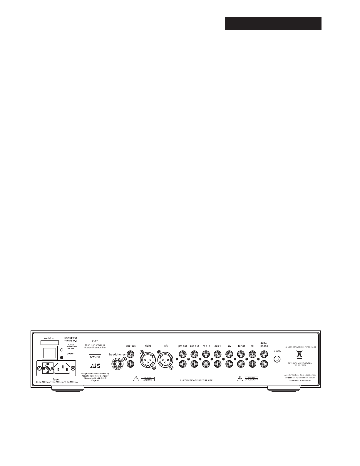
sockets are illustrated in Diagram 1.
Inputs labeled CD, TUNER, AV and AUX1 are at line sensitivity and are electrically
identical. A line-level signal from any source equipment may be connected to any of
these inputs.
The right-hand (viewed from the rear) pair of AUX2/PHONO input sockets function
as a high sensitivity phono input. All inputs are via RCA phono connectors.
Diagram 1 - CA2 rear panel and connection sockets
Page 6
4
4
CA2
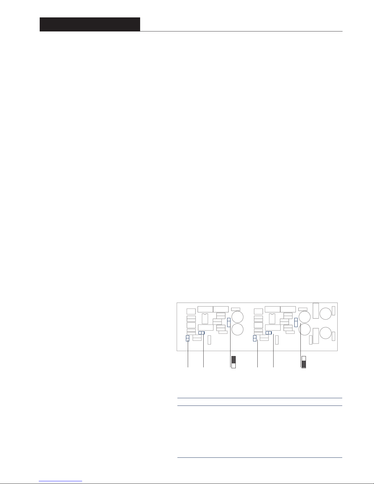
Diagram 2 - RIAA Phono Board and Jumpers
Table A - RIAA Jumper Settings
J1
J2 J3
Pos A
Pos B
J4 J5 J6
Jumper settings for 1 Volt Output
Sensitivity J1 and J4 J2 and J5 J3 and J6
10.0mV Removed Fitted (100Ω ) Position A
6.7mV Removed Removed (47kΩ ) Position A
5.1mV Removed Fitted (100Ω ) Position B
3.4mV Removed Removed (47kΩ ) Position B
2.2mV Fitted Fitted (100 ) Position A
1.4mV Fitted Removed (47kΩ ) Position A
1.1mV Fitted Fitted (100Ω ) Position B
0.7mV Fitted Removed (47kΩ ) Position B
Pos A
Pos B
Preamplifier
The phono amplifier can be configured to
accommodate a wide selection of phono cartridge
types by setting combinations of the board
mounted jumpers (links). Access to the phono
stage is gained by removing the cover of the
preamplifier. Diagram 2 illustrates the position of
the jumpers on the board while Table A details the
cartridge matching options available.
Pulling them gently away from the board with a
small pair of pliers and replaced in the appropriate
positions as shown in the diagram moves links.
Unused links can be “parked” on the board by
setting them at right angles on unused pins.
Jumpers J2 and J5 set the input load for each
channel of the cartridge. With the jumper in place
the load is 100 ohms. With the jumpers removed
the load is 47k ohms.
Jumpers J3, J6, J1 and J4 set the gain (sensitivity) of
the phono input. J3 and J6 have two positions A and
B. In position A the gain of the phono stage is
reduced, in position B the gain is increased. J1 and
J4 can have the jumper fitted or removed. When
fitted the gain of the circuit is increased. By setting
combinations of these 4 jumpers, a range of
sensitivities can be accommodated.
For example: for a cartridge with a low sensitivity
J3 and J6 would be set in position B while J1 and
J4 would both have their jumper fitted. Table
A illustrates the input sensitivity and load
characteristics available. The manufacturer of the
cartridge in use will be able to recommend the
appropriate settings.
Page 7
5
5
1.3 Outputs
The CA2 rear panel illustrated in Diagram 1 carries sockets for
main left and right output, tape left and right output, left and
right summed mono output and an output for stereo
headphones. Use of the headphone jack will mute the output
from the main stereo output and also the sub output.
Connections to the main output may be from RCA phono
plugs or XLR plugs. Connections to the XLR output sockets
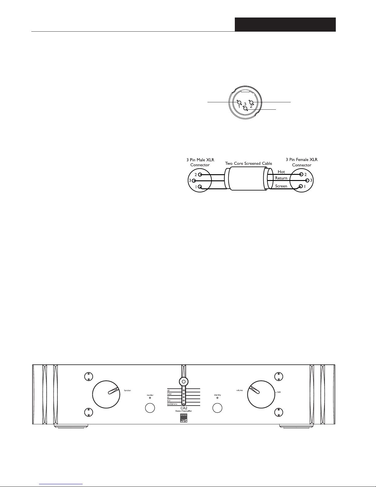
follow the convention of pin 1 to ground, pin 2 to signal “hot”
and pin 3 to signal return (signal ground). When connecting to
equipment with XLR (balanced) inputs, the connectors should
be wired pin for pin (i.e. 1 to 1, 2 to 2, and 3 to 3). Diagram 3
illustrates the XLR output pin arrangement. Diagram 4
illustrates the cable arrangement for connection to balanced
inputs.
Cables up to 50 metres in length may be connected to the main
stereo or sub outputs.
1.4 Operation
Once connected to mains power and powered up from the
rear panel mains switch, the front panel Standby button (or remote handset Standby
button) will switch the CA2 between standby and active mode. In Standby mode the
Standby Indicator glows RED. Operating the Standby function from either the front
panel or the remote handset will switch the CA2 into active mode. The RED
indicator will extinguish and be replaced by the Input select indicator showing the
current selection in GREEN. Operating the Standby function again will return the
CA2 to Standby mode.
Inputs are selected by rotating the input select control in either direction. The
control has continuous movement. When it is moved to the last input, further
rotation will select the first input.
A separate tape loop is included with a Monitor option selected by a single push
button on the front panel. The tape output will have the same signal as selected by
the rotary input select control. Operation of the Standby or tape monitor controls
will not affect this output providing mains power is maintained.
Diagram 6 - CA2 front panel and controls
CA2
Preamplifier
Diagram 3 - output socket pins
Pin 2, Signal (hot)Pin 1, ground
Pin 3, Signal (return)
Diagram 4 - balanced cable
To Power Amp or
Monitor Input
To Preamp Output
Page 8

6
Preamplifier
E. & O.E. The policy of Loudspeaker Technology Ltd. is that of continuous design and development. We reserve the right to change
specifications without prior notice.
1.5 Specifications
Maximum Output Level 7.5V RMS into 600 Ohms
Line Input Sensitivity (for 1V Output): 150mV
R.I.A.A. Input sensitivity: See Table A
R.I.A.A. Input Impedance: See Table A
R.I.A.A. Accuracy (20Hz – 20kHz): ±0.5dB
Input Impedance:
5k Ohms
Output Impedance: 10 Ohms
Frequency Response (-3dB): DC – >500kHz
Total Harmonic Distortion: <0.0005% (-106dB) 1V into 600 Ohms
Crosstalk (10Hz – 20kHz) >90dB
S+N/N Ratio: >95dB (Wide band)
>104dB (DIN)
>108dB (IEC "A")
Power Requirements 100, 115, 230V, 50/60Hz
Power Consumption 35VA Maximum
Dimensions (including terminals) H90 x W445 x D330mm
H3.54 x W17.5 x D13.0 inches
Weight 7kg (15.4lb) Net
8kg (17.6lb) Packed
CA2
Output level is controlled by the rotary Volume
control on the front of the unit, the position of
which is indicated by a black pointer. Rotating the
control clockwise will increase the output level. It
is good practice to lower the volume setting before
switching on the preamplifier or any associated
equipment, or while changing the input selection.
Unity gain though the CA2 from any of the line
level inputs is indicated by the ‘0dB’ print on the
front panel, beside the volume control. This is the
volume position the preamp should be set to for
‘Home Cinema Bypass’ so the CA2 has no
influence on signal level when used within a cinema
surround system.
Due to the nature of the electronics in ATC
amplifiers it is quite normal for a sound to be heard
from the speaker when the power is applied or
disconnected. The noise heard will not damage the
speaker and is quite normal. Although ATC uses the
highest-grade components, a different noise may be
heard from each speaker due to slight tolerance
variations in the amplifier components.
Page 9

7
SCA2
2.1 Description
The SCA2 is an extremely high resolution preamplifier designed to partner ATC
active, and, with an appropriate power amplifier, passive loudspeaker systems. It
incorporates eight line-level stereo inputs, two stereo signal outputs and two stereo
record outputs. Two of the line inputs are balanced format on XLR sockets while the
remaining inputs are unbalanced and on pairs of RCA phono sockets. The main
stereo output is balanced format on a pair of XLR sockets while the auxiliary stereo
output is unbalanced and on a pair of RCA phono sockets. The two record outputs
are unbalanced on pairs of RCA phono sockets.
The AUX 2 line-level input may be converted to function as a high-sensitivity phono
input through the addition of a factory fitted optional RIAA Phono Board. The RIAA
board carries an array of slide switches that enable optimal matching with phono
cartridges of various output voltages and loading requirements.
Selection of SCA2 inputs is achieved via a eight-position rotary control using gold
plated relays for silent switching. The SCA2 incorporates an independent record
output signal path so enabling simultaneous listening and recording of different source
signals. Selection of the record output signal is achieved via a second eight-position
rotary control using gold plated relays for silent switching.
Output volume adjustment is achieved through a precision motorised potentiometer.
Mute, gain and standby functions are also accessible from font panel push buttons.
Mains power is applied from a rear panel mounted switch.
All SCA2 functions are duplicated on the ATC SCA R remote control handset.
Preamplifier
2.2 Inputs
The SCA2 can accept two balanced XLR inputs
and six unbalanced RCA phono style inputs (2 as
part of tape record/listen sets). The rear panel and
input sockets are illustrated in Diagram 1. The input
types and their identifying legends are illustrated in
following Table A.
The AUX 2 input sockets will function as a high-
sensitivity phono input if the optional SPH2 RIAA
Vinyl Board is installed. The RIAA circuitry can be
configured to accommodate a wide selection of
phono cartridge types by setting combinations of
board mounted links. Access to the board is gained
by removing the top panel of the preamplifier.
Diagram 2 illustrates the position of the links on
the board while Diagram 3 and Table B detail the
c
artridge gain and input matching options
available.
Links are moved by pulling them gently away from
the board with a small pair of pliers and are
replaced in the appropriate positions as shown in
the diagrams. Unused links can be “parked” on the
board by setting them at right angles on unused
pins.
The SPH2 board is split into two identical channels.
For the sake of clarity on the diagrams, the settings
for only one channel are shown. Settings for one
channel should be duplicated on the other. The
cartridge gain and matching options should be
used as described on the following page.
Page 10
8
SCA2
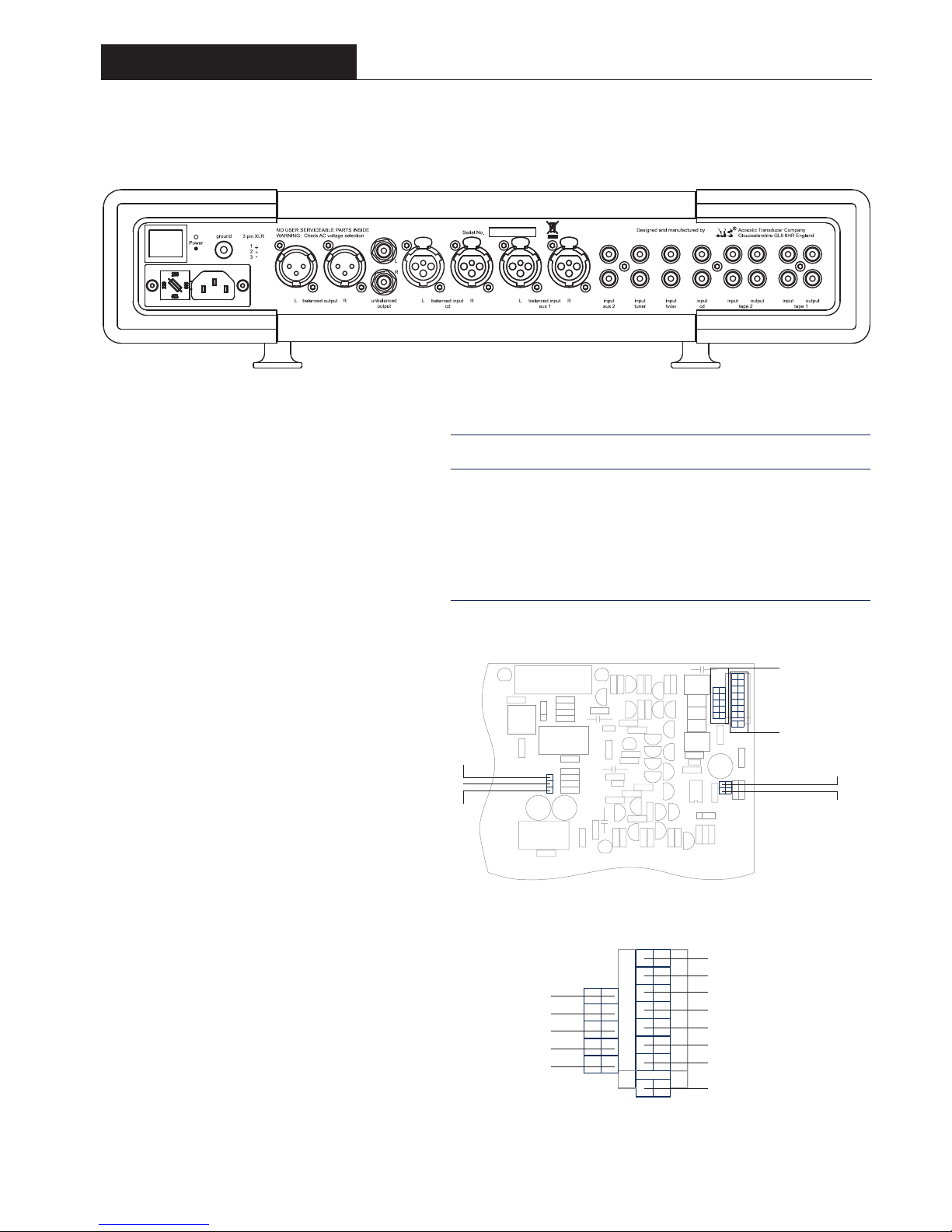
Diagram 1 - SCA2 rear panel and connection sockets
Diagram 2 - SPH2 Board and Link Locations
Diagram 3 - SPH2 Load Capacitor and Resistor Options
Table A - Input Sockets
Input socket types and legends
Rear Panel Front Panel Input Notes
Legend Legend Type
balanced input cd cd bal XLR balanced x 2
balanced input aux 1 aux 1 XLR balanced x 2
input aux 2 aux 2 RCA phono x 2 Marked “phono” on rear if
SPH2 RIAA board fitted
input tuner tuner RCA phono x 2
input tv/av a/v RCA phono x 2
input cd cd RCA phono x 2
input tape 2 tape 2 RCA phono x 2 Part of record/listen set
input tape 1 tape 1 RCA phono x 2 Part of record/listen set
Z1
Z2
Z3
X-X
Y- Y
Resistor bank.
See Diagram 3
Capacitor bank.
See Diagram 3
Link across for 400 ohms
Link across for 500 ohms
Link across for 300 ohms
Link across for 600 ohms
Link across for 200 ohms
Link across for 700 ohms
Link across for 100 ohms
Trim -50 ohms
Link across for 2200pF
Link across for 1000pF
Link across for 470pF
Link across for 220pF
Link across for 100pF
Preamplifier
Page 11
9
SCA2
Preamplifier
Table B - RIAA Board Gain Stage Link Setting
Mid point gain stage set LOW (11dB) Link Z1 to
Z2
First gain stage settings.
Gain Setting Gain mV Gain dB Link Position
High 1.14mV 59dB Link both Y-Y and X-X
High/mid 1.6mV 55dB Link Y-Y only
Mid 3.3mV 49dB Link X-X only
Low 33.0mV 30dB No links
Mid point gain stage set HIGH (24dB) Link Z2 to
Z3
First gain stage settings.
Gain Setting Gain mV Gain dB Link Position
High 0.25mV 71dB Link both Y-Y and X-X
High/mid 0.38mV 68dB Link Y-Y only
Mid 0.78mV 62dB Link X-X only
Low 7.5mV 42dB No links
Gain: Gain is set by fitting the Z link in one of two positions (Z1 to Z2 or Z2 to Z3)
and by setting a combination of X and Y links. These links should be fitted according
to the desired input sensitivities specified in Table B.
Capacitive Load: Capacitive load is set by selecting a link for the appropriate
capacitance value as illustrated in Diagram 3. Multiple links may be be used, in which
case the load value is the sum of the selected values. For example, links in the 470pF
position and 1000pF position give a total load value of 1470pF.
Resistive Load: Resistive load is set by selecting a link for the appropriate capacitance
value as illustrated in Diagram 3. If no link is selected the default resistive load is 47
kilohms - appropriate for the majority of moving-magnet cartridges. A link in the -50
position will reduce any selected load by 50 ohms. For example,
links in the 200 position and -50 position give a total load
value of 150 .
Cartridge suppliers and manufacturers will be able to provide
details of the loading and gain settings appropriate to their
products. On some occasions there will be no specific
recommendation for the capacitive load on moving-coil
cartridges. In these cases it is best to assume no capacitance
need be selected (no links used).
The rear panel ground terminal should be used to connect
the pick-up arm earth lead.
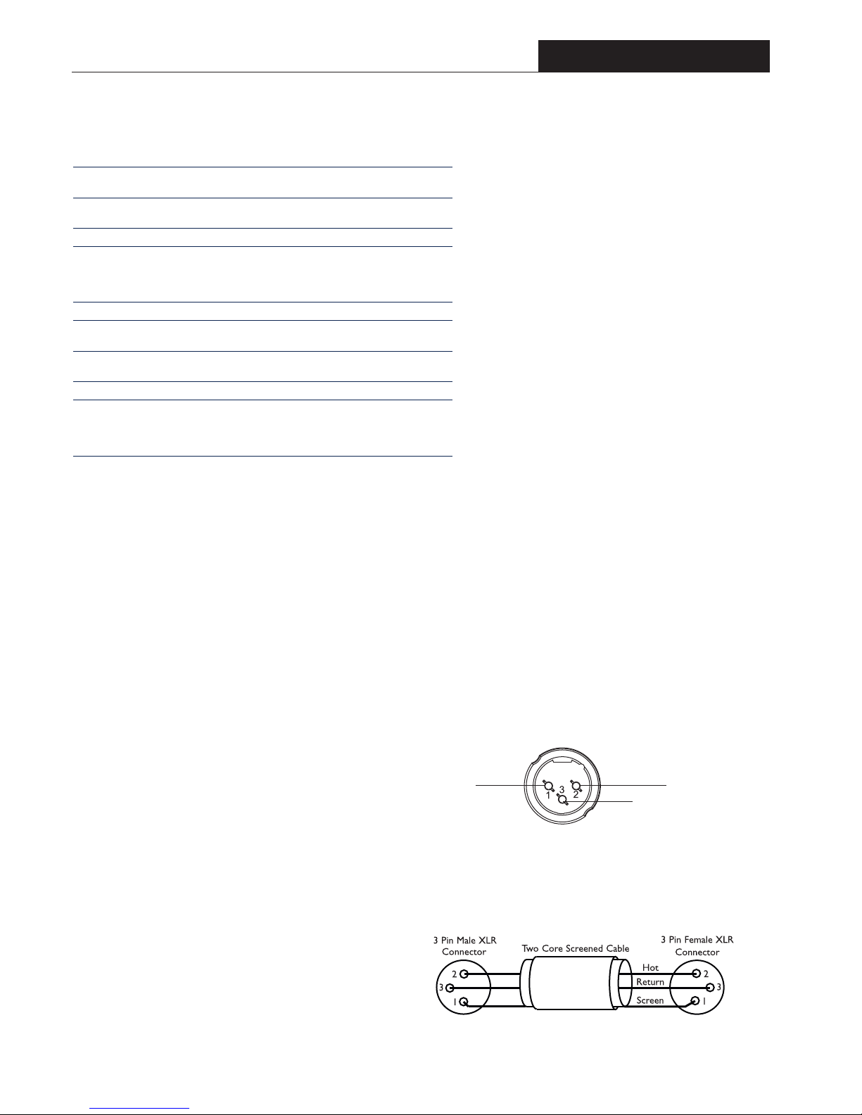
2.3 Outputs
The SCA2 rear panel, illustrated in Diagram 1, carries
sockets for balanced main left and right output, unbalanced
main left and right output, and two unbalanced tape record
outputs.
Choice between the balanced and unbalanced main outputs
will depend on the input capabilities of the following power
amplifier (or active speakers). Use the balanced
option in preference if both options are possible.
Connections to the primary output XLR sockets
follow the convention of pin 1 to ground, pin 2 to
signal “hot” and pin 3 to signal return (signal
ground). When connecting to equipment with XLR
(balanced) inputs the connectors should be wired
pin for pin (ie. 1 to 1, 2 to 2 and 3 to 3). Diagram 4
illustrates the XLR output pin arrangement and
Diagram 5 the connection scheme for a balanced
XLR - XLR cable.
The unbalanced main left and right outputs and the
tape record outputs should be connected using
good quality RCA phono terminated leads. Use of
the front panel volume, mute, or gain functions
does not effect the tape record signal.
Cables up to 50 metres in length may be connected
to the main outputs. Tape record cables should be
limited to 10 metres.
Pin 2, Signal (hot)
Pin 1, ground
Pin 3, Signal (return)
Diagram 4 - balanced output socket pins
Diagram 5 - balanced cable pin connections
To Power Amp or
Monitor Input
To Preamp Output
Page 12
10
SCA2
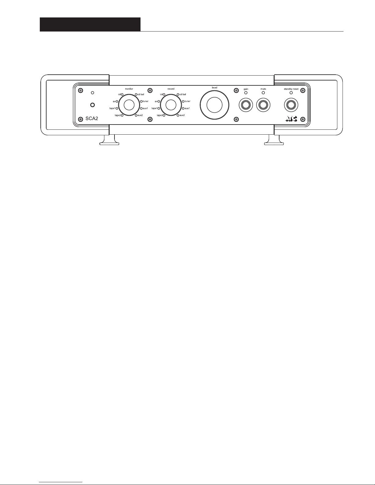
Diagram 6 - SCA2 front panel and controls
2.4 Operation
Once connected to mains power and powered-up
from the rear panel mains switch, the front panel
Standby Reset button (or remote handset Standby
button) will switch the SCA2 between standby and
active modes. In standby mode the Standby Reset
indicator will illuminate. Operating the Standby
Reset function will switch the SCA2 into active
mute mode. The Standby Reset indicator will
extinguish and the Mute indicator will illuminate.
The Mute function automatically engages when the
SCA2 is switched from standby to active mode.
This precautionary feature provides an opportunity
for the volume and input settings to be checked
before audio is passed to the power amplifiers.
If all is well, the SCA2 may be brought into full
operation by pressing the Mute function. The Mute
indicator will extinguish. The Mute function can be
used at any time to silence the system.
Inputs are selected by rotating the Monitor select
control. The green indicator next to each monitor
option will illuminate to indicate selection. The
control has continuous movement. When it is
moved to the last input, further rotation will select
the first input.
Volume level is adjusted by rotating the Level
control. A red indicator on the control indicates
the level selected.
Volume level can be reduced immediately by 12dB
by operating the Gain function. The Gain indicator
illuminates to indicate its use.
Optimum sound quality will be achieved when the SCA2 has reached normal
operating temperature and for this reason it is recommended that it be left in
standby mode when not in use. It is a wise precaution however to switch-off the
SCA2 from the rear panel power switch if it is to be left unused for an extended
period.
The Record select control selects the input source routed to the tape outputs. The
green indicator next to each record option will illuminate to indicate selection. The
control has continuous movement. When it is moved to the last input, further
rotation will select the first input. The source selected is made available at the tape
output sockets and is fully buffered to prevent signal interaction. The Level, Gain and
Mute functions have no effect on the record output signals.
Tape copying can be performed by selecting Tape 1 on the Record control to copy
from Tape 1 to Tape 2. In this case no signal will be routed to the Tape 1 output
sockets. Copying from Tape 2 to Tape 1 can be achieved in a similar manner.
Selecting Tape 1 on the Monitor control while also recording to Tape 1 (i.e. tape 1
is also selected on the record control) enables the off-tape signal from a three head
tape machine to be monitored. The Tape 2 circuit works in an identical manner.
Due to the nature of the electronics in ATC amplifiers it is quite normal for a sound
to be heard from the speaker when the power is applied or disconnected. The noise
heard will not damage the speaker and is quite normal. Although ATC uses the
highest-grade components, a different noise may be heard from each speaker due to
slight tolerance variations in the amplifier components.
Preamplifier
Page 13

11
2.5 Specifications
MAIN OUTPUTS
Maximum Output Level 8.5V RMS into 600 Ohms balanced
17.5V RMS into 600 Ohms unbalanced
Input Sensitivity (for 1V Output) 230mV
Input Impedance Phono (Unbalanced) 20k Ohms
XLR (Balanced) 2k7 Ohms per leg
Output Impedance 10 Ohms
Frequency Response (-3dB) DC - 500kHz
Total Harmonic Distortion 0.0005% (-106dB) @ 1V into 600 Ohms
Crosstalk (10Hz – 20kHz)
>
90dB
S+N/N Ratio: >95dB (Wide band)
>104dB (DIN)
>108dB (IEC "A")
Residual noise
>
116dB (IEC "A")
Absolute phase Phono (Unbalanced) Zero Degress
XLR (Balanced) Zero Degrees, Pin 2 Hot
XLR CMRR (100Hz – 10kHz)
>90dB
Power Requirements 100V, 120, 220, 230V 50/60Hz
Power Consumption 35VA maximum
Dimensions (including terminals) H100 x W440 x D360mm
H3.9 x W17.3 x D14.2 inches
Weight 9.5kg (20.9lb) Net
11.0kg (24.2lb) Packed
SCA2
Preamplifier
E. & O.E. The policy of Loudspeaker Technology Ltd. is that of continuous design and development. We reserve the right to change
specifications without prior notice.
Page 14
ACOUSTIC
ENGINEERS
P1
12
P1 & P2
Power Amplifiers
3.1 Description
The P1 and P2 are high quality power
amplifiers designed to partner ATC passive
monitors and other loudspeaker systems. The
amplifiers incorporate the same gain reduction and
loudspeaker protection circuits as used in the
ATC active monitors. This ensures that even
when working at very high levels the amplifier is
held back from clipping, so improving the
subjective performance and protecting the
loudspeakers from damage.
Both the P1 and P2 are of a "true" Dual Mono
design, in that the power supplies signal and return
paths are totally separated from each other. This
approach ensures that the Amplifier will
achieve the maximum signal separation and
minimum crosstalk. Further, intermodulation
between channels via the power supplies is
reduced to an absolute minimum at all
frequencies, and, the power delivery from one
channel cannot affect the specified power available
from the other channel.
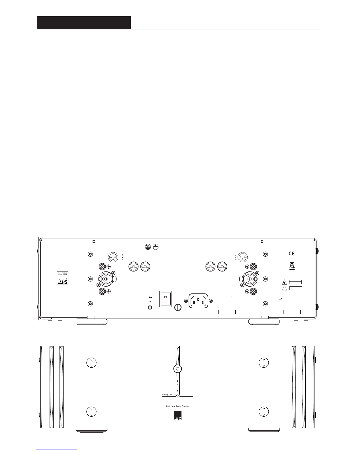
Diagram 1 - PI rear panel and connection sockets
Diagram 2 - PI front panel
The amplifier mains power is turned on by a switch on the rear panel. There is a
Green L.E.D. on the front panel to indicate that the mains supply is
connected, together with a Red L.E.D. to indicate that the Amplifier is in Standby.
The Amplifier can be brought out of Standby by the Standby button on the
ATC remote control (supplied with P1 and P2). On the rear panel is a push
button to defeat remote control operation in which case, when the
Amplifier is switched on the unit will not be in Standby, The Red L.E.D. will be
off, and the remote control has no effect.
3.2 Inputs
Single ended Inputs via RCA phono sockets, and Differential (balanced) Inputs via
XLR sockets are provided. Each channel has two phono Input sockets, the ”Link”
Input phono sockets may be used to connect the Amplifier Inputs to a further ATC
Power Amplifier for Instance as a Sub Channel.
3.3 Outputs
Loudspeaker connections are made using the two pairs of proprietary ATC
loudspeaker terminals. The left and right channels are clearly marked and
correspond to the left and right inputs. The positive terminal is marked red and the
negative terminal is marked black.
right
output
output
left
input
link out
balanced
input
balanced
input
input
link out
fuse
NO USER SERVICEABLE PARTS INSIDE
CAUTION
RISK OF ELECTRIC SHOCK
DO NOTOPEN
WARNING
THIS EQUIPMENT
MUSTBE EARTHED
!
P1
High Performance
Dual Mono
Stereo Power Amplifier
Designed and manufactured by
Acoustic Transducer Company
Gloucestershire
GL6 8HR
England
power
I
O
RETURN TO MANUFACTURER
FOR DISPOSAL
serial no.
CHECK VOLTAGE BEFORE USE
230V :T3.15AH 250V
115V :T6.3AH 250V
MAINS INPUT
50/60Hz
POWER CONSUMPTION
600W MAX
voltage
can only be safely used lower than 2,000 metres altitude
2000m
can only be safely used in non-tropical weather
2
1
3
1:
2:
3:
2
1
3
1:
2:
3:
Apparaten skall anslutas till jordat uttag
Apparatet må tilkoples jordet stikkontakt
Laite on liitettävä suojakoskettimilla varustettuun pistorasiaan
Acoustic Transducer Co. is a trading name
and
is the registered Trade Mark of
Loudspeaker Technology Ltd.
i.r disable
I
O
Page 15
P2
ACOUSTIC
ENGINEERS
13
P1 & P2
Power Amplifiers
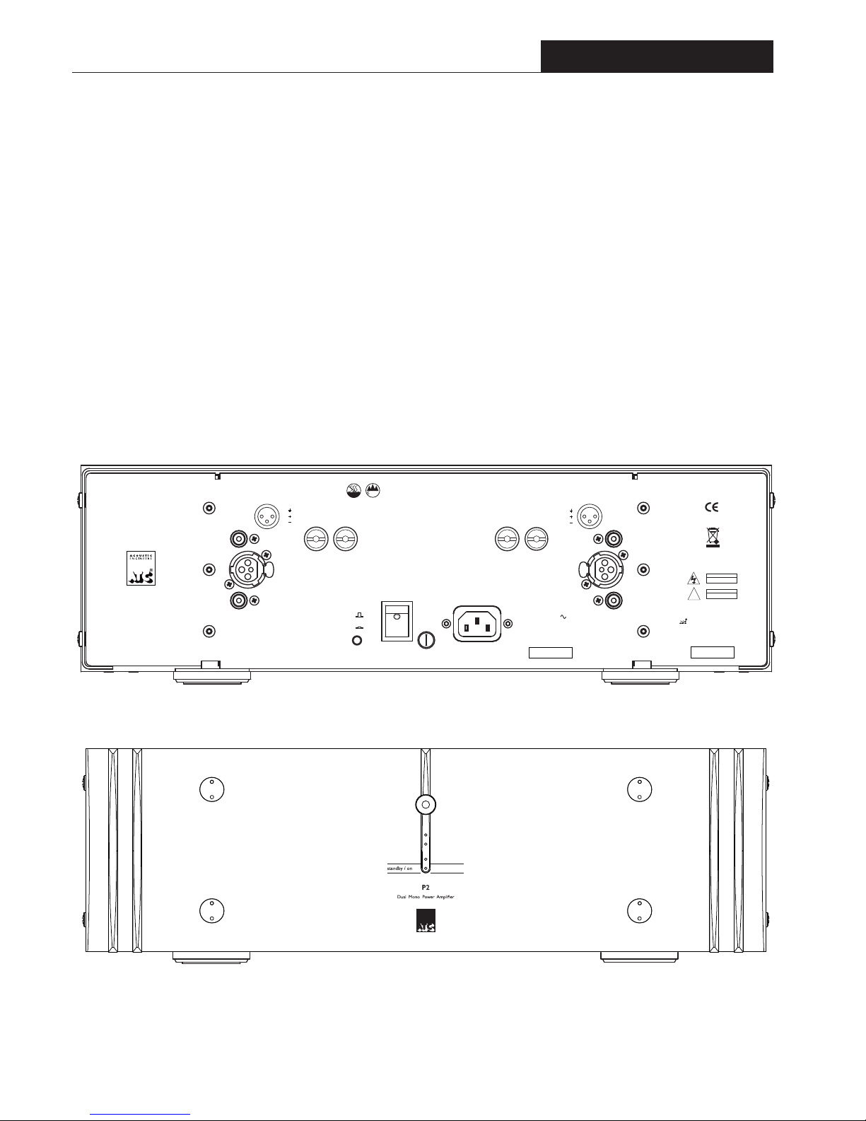
Diagram 3 - P2 rear panel and connection sockets
3.4 Operation
A push button on the rear panel marked “ir disable” defines how the amplifier will
operate once connected to mains power and powered-up from the rear panel
mains switch.
If the push button is “in”, the amplifier will power- up in “active” mode indicated
by a GREEN light on the front panel, the remote control will be inoperative.
If the push button is “out”, the unit will power-up in Standby indicated by a RED
light on the front panel.
Diagram 4 - P2 front panel
The amplifier can be brought out of Standby by
pressing the Standby push button on the remote
control. A further press of the button will put the
amplifier back into standby.
right
output
output
left
input
link out
balanced
input
balanced
input
input
link out
fuse
NO USER SERVICEABLE PARTS INSIDE
CAUTION
RISK OF ELECTRIC SHOCK
DO NOTOPEN
WARNING
THIS EQUIPMENT
MUSTBE EARTHED
!
P2
High Performance
Dual Mono
Stereo Power Amplifier
Designed and manufactured by
Acoustic Transducer Company
Gloucestershire
GL6 8HR
England
power
I
O
RETURN TO MANUFACTURER
FOR DISPOSAL
serial no.
CHECK VOLTAGE BEFORE USE
230V :T5.0AH 250V
115V :T10.0AH 250V
MAINS INPUT
50/60Hz
POWER CONSUMPTION
1000W MAX
voltage
can only be safely used lower than 2,000 metres altitude
2000m
can only be safely used in non-tropical weather
2
1
3
1:
2:
3:
2
1
3
1:
2:
3:
Apparaten skall anslutas till jordat uttag
Apparatet må tilkoples jordet stikkontakt
Laite on liitettävä suojakoskettimilla varustettuun pistorasiaan
Acoustic Transducer Co. is a trading name
and
is the registered Trade Mark of
Loudspeaker Technology Ltd.
i.r disable
I
O
Page 16

14
P1 & P2
Power Amplifiers
P1
P2
Power Output
(1% Distortion, 1kHz, Both
>150W into 8 Ohms
>300W into 8 Ohms
channels driven, Continuous average)
Frequency Response <2Hz – >400kHz
(-3dB)
Distortion
<0.002
% (-95dB)
(1kHz, 8 Ohms, 1dB below full power)
Input Sensitivity 2.0V/3dBV/4.1dBu
(150 Watts, 8 Ohms, 1kHz)
Input Impedance 10k Ohms (Phono)
10k Ohms/Leg (XLR)
S+N/N Ratio >100dB (Wideband)
>110dB (DIN)
>115dB (IEC "A")
Crosstalk >100dB
(10Hz – 20kHz)
Damping Factor >400
(8 Ohms)
Absolute Phase Zero Degrees (Phono)
Zero Degrees (XLR, Pin 2 Hot)
XLR Common Mode Ratio
>60dB
(100Hz – 10kHz)
Power Requirements
115, 230V factory set, 50/60Hz
Power Consumption
600W Maximum 1000W Maximum
Dimensions (H x W x D)
141 x 448 x 337mm
5.6 x17.6 x13.3in
Weight
25kg/ 55lbs
E. & O.E. The policy of Loudspeaker Technology Ltd. is that of continuous design and development. We reserve the right to change specifications without prior notice.
3.5 Specifications
141 x 448 x 337mm
5.6 x17.6 x13.3in
23kg/ 50.6lbs
Page 17
15
Integrated Amplifier
SIA2-150
4.1 Description
The SIA2-150 is a high quality integrated amplifier designed to partner ATC passive
monitors and other Loudspeaker systems. It incorporates five line-level stereo
inputs plus headphone jack, stereo record, pre and sub outputs on RCA phono
sockets and one pair of loudspeaker outputs.
Input selection is achieved via a rotary control. Output volume adjustment is achieved
by a precision potentiometer. Standby is accessible from a front panel push button.
Mains power is applied from a rear panel mounted switch.
The SIA2-150 incorporates the same gain reduction and loudspeaker
protection circuits as used in the ATC active monitors. This ensures that even
working at very high levels the amplifier is held back from clipping so improving the
subjective performance and protecting the loudspeakers from damage.
All SIA2-150 functions are duplicated on the included ATC remote control handset.
4.2 I nputs
The SIA2-150 accepts unbalanced RCA phono input plugs. The signal is present on
the centre conductor of an unbalanced input and the signal return is made via the
screened outer. If there is any hum present on the inputs, this must be traced to its
source and not suppressed by the removal of screens or earths. Removal of
the screen on an unbalanced input is likely to result in uncontrollably loud hum. The
input sockets are illustrated in diagram 1.
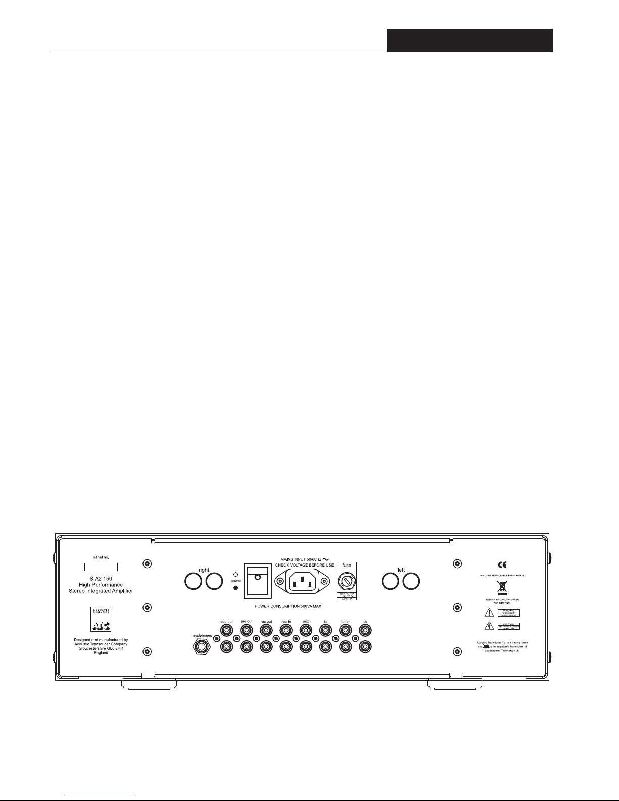
All inputs are line level sensitivity via RCA phono connectors on the rear
panel. Inputs are labeled CD, Tuner, AV, Aux., and Rec. in. However, they are
electrically identical and a line level signal from any source equipment may be
connected to any input.
4.3 Outputs
The SIA2-150 rear panel, illustrated in diagram
1, carries connectors for left and right
loudspeakers, Rec. left and right outputs,
Preamplifier left and right outputs and a left and
right summed mono output.
Loudspeaker connections are made using the two
pairs of proprietary ATC loudspeaker terminals.
The positive terminal is coloured red and the
negative terminal is coloured black. The left and
right channels are clearly marked and correspond
to the left and right inputs. The wire used for the
connections to the monitors will have some
identification for the positive conductor. Usually
this is red,
but may be a moulded stripe on the
insulation.
Diagram 1 - SIA2-150 rear panel and connectors
Page 18
16
SIA2-150
4.4 Operation
Once connected to mains power and powered up
from the rear panel mains switch, the front panel
Standby button (or remote handset Standby button)
will switch the CA2 between standby and active
mode. In Standby mode the Standby Indicator glows
RED. Operating the Standby function from either
the front panel or the remote handset will switch
the CA2 into active mode. The RED indicator will
extinguish and be replaced by the Input select
indicator showing the current selection in GREEN.
Operating the Standby function again will return the
CA2 to Standby mode.
Inputs are selected by rotating the input select
control in either direction. The control has
continuous movement. When it is moved to the last
input, further rotation will select the first input.
A separate tape loop is included with a Monitor
option selected by a single push button on the front
panel. The tape output will have the same signal as
selected by the rotary input select control. Operation
of the Standby or tape monitor controls will not
affect this output providing mains power is
maintained.
A pair of phono sockets on the rear panel can be
used to drive another amplifier. A further pair of
phono sockets can be used to drive a Sub channel
Amplifier.
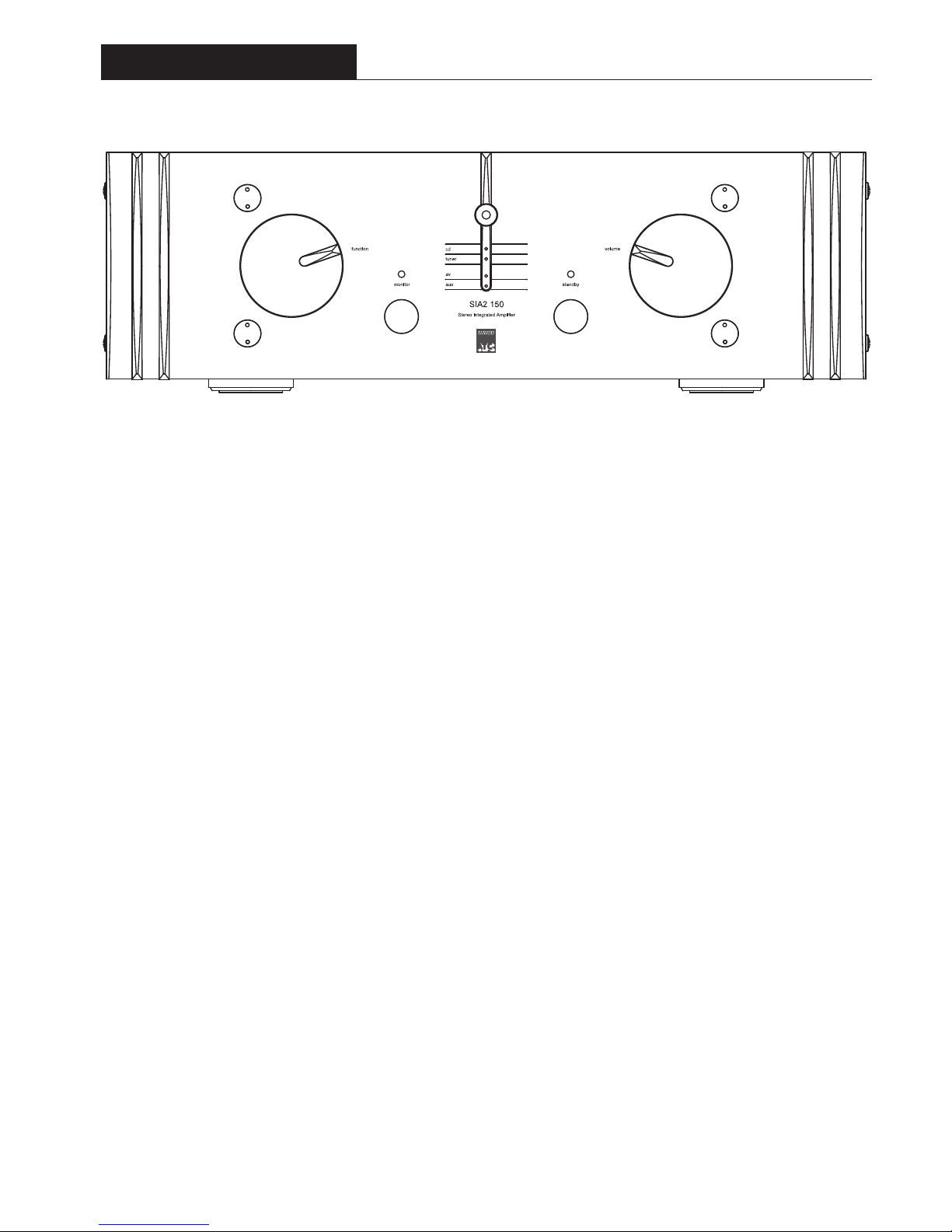
Diagram 2 - SIA2-150 front panel and controls
Integrated Amplifier
A Headphone output is provided via a ¼” Jack socket to drive a variety of popular
headphones. When headphones are connected the signal to the speakers, sub and pre
out is muted.
Output level is controlled by the rotary Volume control on the front of the unit, the
position of which is indicated by a black pointer. Rotating the control clockwise will
increase the output level. It is good practice to lower the volume setting before
switching on the preamplifier or any associated equipment, or while changing the input
selection.
Due to the nature of the electronics in ATC amplifiers it is quite normal for a sound
to be heard from the speaker when the power is applied or disconnected. The noise
heard will not damage the speaker and is quite normal. Although ATC uses the highest-
grade components, a different noise may be heard from each speaker due to slight
tolerance variations in the amplifier components.
Page 19

17
SIA2-150
Specifications
4.5 Specifications
Power Output >150 Watts
(1% Distortion, 1kHz, Both
channels driven, Continuous average)
Frequency Response <2Hz – >400kHz
(
-3dB)
Distortion <0.002% (-95dB)
(1kHz, 8 Ohms, 1dB below full power)
Input Sensitivity 350mV
(150 Watts, 8 Ohms, 1kHz)
Input Impedance 20k Ohms
S+N/N Ratio >100dB (Wideband)
Crosstalk >90dB
(10Hz – 20kHz)
Absolute Phase Zero Degrees (Phono)
Power Requirements 100, 115, 230V factory set, 50/60Hz
Power Consumption 10VA Standby
500VA Maximum
Dimensions (H x W x D)
135 x 435 x 350mm
(Including terminals)
5.31 x 17.1 x 13.8 inches
Weight
20kg/44lbs Net
22.2kg/48.8lbs Packed
E. & O.E. The policy of Loudspeaker Technology Ltd. is that of continuous design and development. We reserve the right to change
specifications without prior notice.
Page 20

ACOUSTIC
ENGINEERS
Acoustic Transducer Company is the trading name and ATC is the registered trade mark of Loudspeaker Technology Ltd.
Loudspeaker Technology Ltd Gypsy Lane, Aston Down, Stroud, Gloucestershire GL6 8HR United Kingdom
Telephone 01285 760561 Fax 01285 760683
Email: [email protected] We b: www.atcloudspeakers.co.uk
 Loading...