

Page 1
_____________________________________________________________________________________________________________
7DT-2CH 7-Day Timer
INSTALLATION & OPERATION MANUAL
______________________________________________________________________________________________________________
Page 2

Table of Contents Page
I. Specification…………………………………………………………. 2
II. Warning………………………………………………………………. 2
III. Features of the Device……………………………………………… 3
IV. Controls/Menu Description…………………………………………. 3
1. Menu Flow Chart…………………………………………………... 3
2. Description of the Device…………………………………………. 4
3. Description of the Control Buttons and Mode………………….. 4
4. Economical Mode………………………………………………….. 5
5. Illumination of Display……………………………………………… 5
6. Reset the Time, Date, and Year…………………………………. 5
7. Reset all the Programs……………………………………………. 5
V. Setting the Date and Time………………………………………….. 6
VI. Programming…………………………………………………………. 7
1. Mode Priorities……………………………………………………… 7
2. Normal Mode……………………………………………………….. 7
3. Repeat Cycle Mode……………………………………………….. 9
4. Pulse Mode…………………………………………………………. 10
5. Random Switching Mode………………………………………….. 11
6. Manual Mode……………………………………………………….. 12
7. Cycle/Pulse Output Setting……………………………………….. 12
8. Editing Programs…………………………………………………… 13
9. Deleting Programs…………………………………………………. 13
10. Setting the Holiday Mode………………………………………….. 14
1
Page 3

I.) Specification:
Model 7DT-2CH
Power Supply Universal 12-240 VAC or VDC (50-60 Hz)
Power Consumption AC 0.5-2 VA / DC 0.4-2W
Allowable Operation Voltage -15%; +10%
Number of Outputs 2 Independent Form C Relay Outputs
Contact Rating 2 Independent SPDT (Single Pole Double
Throw Contact)
16 amps @ 250 VAC & 24 VDC Resistive Load
Switching Capacity 4000 VA/AC, 384 W/DC
Peak Current 30 amps / <3 sec.
Mechanical Durability >30,000,000 operations
Electric Durability >70,000 operations
Operational Backup during Power Failure Up to 3 years
Accuracy of the Operating Max. +/- 1 Second Day at 20º
Minimum Run Time 1 minute (Normal Mode); 1 second (Pulse
Mode); 2 second (Cycle Mode)
Number of Memory Places 100
Display LCD
Operational Temperature -10º to 55º C
Storing Temperature -30º to 70º C
Dimension 90 x 35.6 x 64 mm
Weight 137 grams
II.) Warning:
The device is made to be connected to Single-Phase AC and DC voltage and must be installed in
accordance with rules and standards applicable in the particular country. The installation,
connecting, setting and handing can be done only by a person with the adequate
electromechanical qualification, who is well informed about the function of this device and the
manual.
Before you start with installation, make sure that the device is not energized and that the main
switch is in the “OFF” position.
Do not install the device to the sources of excessive electromagnetic disturbances. Assure an
excellent circulation of the air by correct installation so the maximal operating temperature of the
device is not surpassed even in case of permanent operation and higher temperature of the
surrounding. To install and set, use a screwdriver with 2 mm dimension. Be aware of the fact
that it is a fully electronic device while handing it.
Proper function of the device depends on the transport, storing and handling. If you find any
marks of damage, missing part, or if the device seems not operational, do not install this device
and claim the warranty at your distributor. After completion of the useful life of the device it must
be stored in protective waste dump.
2
Page 4
III.) Features of the Device:
Two-channel version, mounting on DIN rail, terminals
Daily and weekly program in one device
Power supply 12-240 VAC / VDC
Functions: according to the user program, manual, random, and holiday program modes.
100 memory places, illuminated LCD display
Operational back up – up to 3 years
Pulse and repeat cycle output
*Before you start programming this timer switch, please make sure to read
carefully through the following instructions.
IV.) Controls/Menu Description:
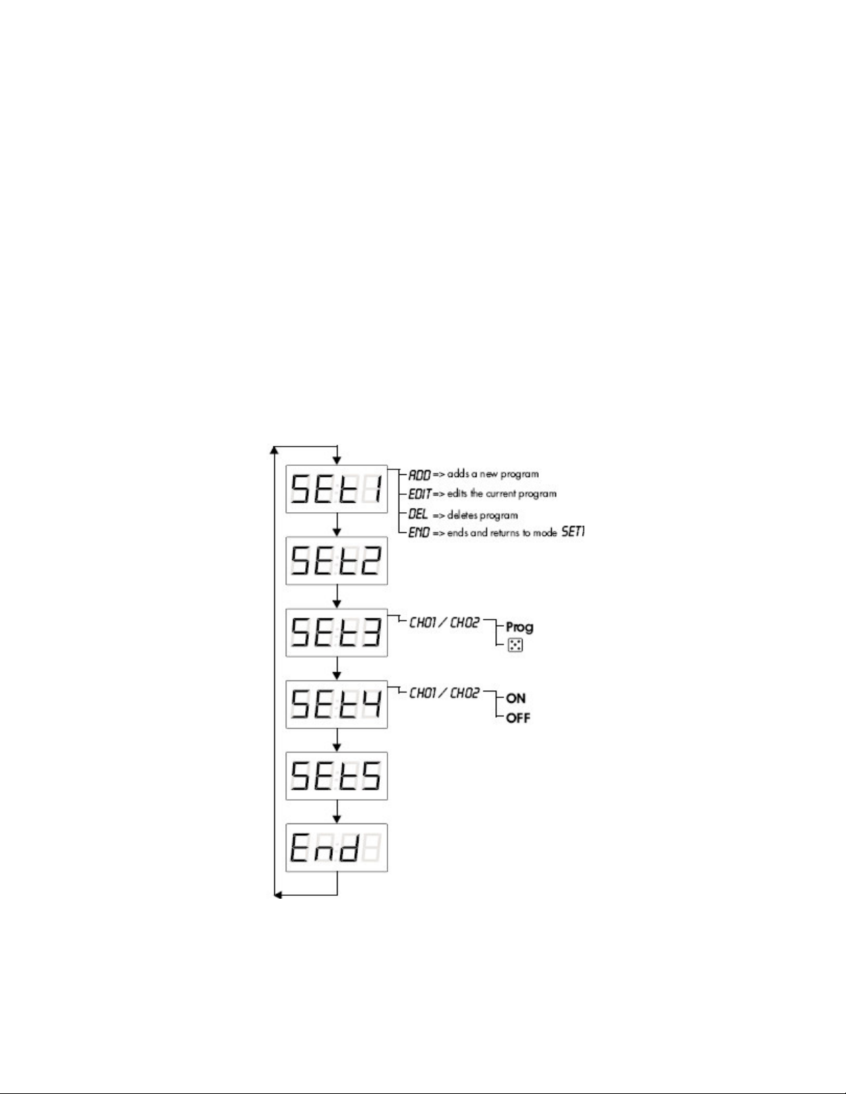
1.) Menu flow chart
3
Page 5
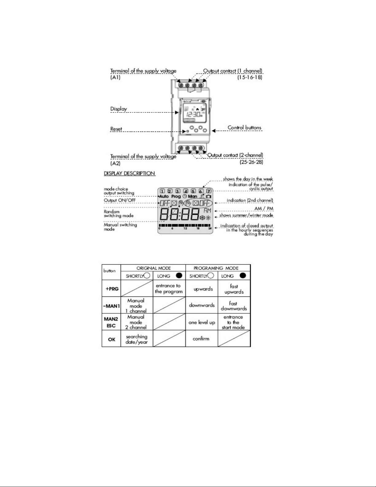
2.) Description of the Device
3.) Description of the Control Buttons and Modes
a) There are four control buttons located on the face of the unit just below the
display
b) First button going from left to right is the (PRG button) this button is used to
enter the program setup menus by pressing and holding it down for 3
seconds
c) The PRG button has a plus sign (+) located right below the PRG on the face
d) The next button on the right of the (+PRG) button is the (-MAN) button
e) The (MAN) button can be quickly pressed while in the run mode operation to
quickly turn on output 1 on and off manually
4
Page 6

f) There is also a minus sign (-) located underneath this button which means
that when the unit is in the program mode, this button can be quickly pressed
to go back to the previous screen or menu
g) The third button from the left is the (MAN2) which works just like the MAN
button except it controls the output 2 relay during run mode
h) The third button from the left also works as a double button (ESC), which is
used during the program mode to exit out of the menu or out of the program
mode and back to the run mode
i) The button on the far right is the (OK) button
j) The (OK) button can be used to scroll through the date, time, and year
setting during run mode operation by quickly pressing the button
k) The (Ok) button is also used as the enter button from entering the program
parameters in the program mode
4.) Economical Mode
The 7DT-2CH is shipped with a pre-programmed real time in economical mode.
The unit uses battery memory which allows the unit to keep data stored even when the
unit does not have supply voltage on terminals A1 and A2. This device is capable of
viewing the time with no supply voltage present by pressing any of the control buttons for
two seconds. The 7DT-2CH display will illuminate and display pre-set time. When
supply voltage is connected to terminals A1 and A2 the unit will continuously display the
timing switch’s status until supply voltage is removed.
5.) Illumination of Display
The 7DT-2CH illuminates whenever one of the control buttons are pressed and
remains that way for 10 seconds after the last button was pressed. To have the LCD
display stay illuminated permanently. The three control buttons (ESC/MAN2), (-MAN1),
and the (OK) must be pressed and held down together from 3 second. The display will
flicker once to show that the permanent illuminated feature has been entered. The same
three buttons again must be pressed and held down simultaneously to turn the display
illumination feature off. The display will flicker and than turn the display light off.
6.) Reset the Time, Date, and Year
The 7DT-2CH has a small hidden reset button located on the front left side of the
unit (this can be seen on page 4 under description of the device). By using a pin with a
diameter no bigger than 2 mm you can press this small hidden reset button (when
pressed the screen will go blank). Upon releasing the button the display will show SHT-1
for 3 seconds (This is the version of firmware used) and go to starting mode. The reset
will delete the real time, the set time of the pulse/cycle mode and all temporary functions.
Reset will keep the set programs.
7.) Reset all the Programs
All storied programs can easily be erased by pressing down and holding both
(+PRG) and (OK) buttons simultaneously for a few seconds. The word ALL will be
displayed once the two control buttons have been held down. Now just push the (OK)
button and the unit will delete all existing programs
5
Page 7

V.) Setting the Date and Time
a) Press and hold the (+PRG) button for 3 seconds, is what
will display on the LCD screen (also you will see prog in the upper left corner
of the display)
b) Now press the (+PRG) button to move to the next program option,
symbol in the upper middle part of the display screen)
c) Press the (OK) button to enter the year setting menu (once in
the display should have the last to digits blinking)
d) By using the (+PRG) and the (-MAN) buttons you can change the year
e) Once you have the number on the correct year press the (OK) button to
save it to the memory and move to the next set up option
f) 7DT-2CH display should have the first two digits blinking waiting on a new
day to be entered
g) Again use the (+PRG) and the (-MAN) buttons to change the two digits to the
correct day of the month
h) Press (OK) button to enter the day into the memory of the 7DT-2CH
i) The day is still displayed on the first two digits and now the second two digits
are blinking
j) Once again by using the (+PRG) and the (-MAN) buttons you can scroll up
and down to change the numeric values to represent the month of the year
(1-12)
k) Press (OK) button
l) Now 24 is blinking (the unit will be in military time in this setting: example
13:30 is 1:30 P.M.)
m) Use the (+PRG) or (-MAN) buttons to choose between the 24 hours setting
or the 12 hour setting (In 12 hours setting unit uses a.m. and p.m.)
n) Press the (OK) button on either the 24 or 12
o) Now use the (+PRG) and (-MAN) buttons to set the hours digits of the timer
p) Press the (OK) button
q) Now use the (+PRG) and (-MAN) buttons to set the minutes digits of the
timer
r) Press the (OK) button to enter the data into memory
s) Now the unit will display On or OFF with two symbols representing summer
is now shown on the LCD screen (also you will see a
and winter to the right
t) Use the (+PRG) or (-MAN) buttons to scroll between the two chooses (On or
OFF)
6
Page 8

u) If you choose OFF and press (OK) button, the display will return back to the
menu
v) If you choose On and press (OK) button, you need to select the snow flake or
sun star by scrolling with (+PRG) or (-MAN) buttons and than pressing the
(OK) button (automatic switching is activated)
w) After correct symbol of the seasonal time has been chosen than press the
(OK) button and the display will return to the
x) Press the (ESC/MAN2) button to exit out of the program mode and back to
the original run mode
VI.) Programming
1.) Mode Priorities
menu
2.) Normal Mode
In the normal mode, output is switched according to the set start
and stop time. You must first program a start time and which days of the
week that the output is to turn on. Next you need to program the end time
for the 7DT-2CH unit to turn off the output at a giving time for each set
day.
a) Press and hold the (+PRG) button for 3 seconds, is what
shows on the LCD display ( also you will see prog in the upper left corner of
the display)
7
Page 9

b) Press the (OK) button to enter into the programming parameters (the word
ADD will be shown now)
c) Press the (OK) button (information about the number of the new program
Pr.XX) example: this just gives a numeric values to the
memory location of this program
d) Now press the (OK) button (Ch01 or Ch02 should display)
e) You can choose weather to control output 1 or output 2 by scrolling between
them with the (+PRG) or (-MAN) buttons
f) Press (OK) button,
[Note - If the screen doesn’t look like this than scroll with (+PRG) or (-MAN)
buttons until it does]
g) Press (OK) button
h) The two hours digits on the left side of the display should be blinking, adjust
the numbers using the (+PRG) or (-MAN) buttons to set the desired hour that
you want the output to come on and than press the (OK) button
i) Now the two minutes digits are blinking on the right side of the display, adjust
the numbers using the (+PRG) or (-MAN) buttons to the desired minute time
that you want the output to come on and than press the (OK) button
j) Now it is time to select which days of the week this program will be on for by
pressing the (OK) button on either on or off along with the corresponding
number in the top of the display that represents the days of the week,
k) Choose ON or OFF by using (+PRG) or (-MAN) to scroll between the two
chooses and (OK) to enter the choose (the numbers at the top represent the
days of the week by the number 1 = Monday and the 7 = Sunday)
l) Once the last day has been entered the word ADD is displayed and the two
indicator bars will increase from left to right on the display and once the
program has been saved the unit will say ADD with no indicator bars
illuminated at the bottom of the screen
m) Press (OK) button, (will go back to the PR.XX screen the difference this time
is that the numeric values has increase by one: example PR.01 when you
entered the first program but now the display will read PR.02)
n) Press (OK) button again, (now the display reads either CH01 or CH02
depending on which output you entered in the last program)
o) Choose the same output channel as before so than you can enter a stop time
for the output
p) Press (OK) button, (Out should be displayed on the screen just like in step f
except the word OFF should shows up in the upper left corner, [Note - If the
screen doesn’t look like this than scroll with (+PRG) or (-MAN) buttons until it
does]
q) Press (OK) button
r) Now repeat steps H through L to enter the time of day and which days of the
week you want to turn the corresponding output off [ Note: make sure to
choose the same days of the week to be ON in step J has you did in the
previous program set up]
should be displayed on the LCD screen
8
Page 10

s) Once programming is completed and the word ADD is again displayed and
you are finished adding programs then hit the (MAN 2/ESC) button twice to
exit back to original run mode (the indicator bar that goes with the
corresponding output should be illuminated at the button only on times where
the output is going to be on for that day)
3.) Repeat Cycle Mode
The repeat cycle mode works the same way as the “normal mode”
except the output cycles on and off between set times. The output will
turn on and off for what ever the predetermined time was set in the,
“Cycle/Pulse Setting”, section on page 12. Both the on and off time have
a range of 1 to 99 seconds each.
a) Press and hold the (+PRG) button for 3 seconds, is what
shows on the LCD display (also you will see prog in the upper left corner of
the display)
b) Press the (OK) button to enter into the programming parameters (the word
ADD will be shown now)
c) Press the (OK) button, (information about the number of the new program
Pr.XX) example: this just gives a numeric values to the
memory location of this program
d) Now press the (OK) button, (Ch01 or Ch02 should display)
e) You can choose weather to control output 1 or output 2 by scrolling between
them with the (+PRG) or (-MAN) buttons
f) Press (OK) button,
g) Use the (+PRG) or (-MAN) buttons to scroll through menu options so that the
display looks like it does in step F, EXCEPT the sign is illuminated in the
upper right of the display screen as well (this is how the repeat cycle mode is
activated)
h) Press the (OK) button
i) The two hours digits on the left side of the display should be blinking, adjust
the numbers using the (+PRG) or (-MAN) buttons to set the desired hour that
you want the output to come on and than press the (OK) button
j) Now the two minutes digits are blinking on the right side of the display, adjust
the numbers using the (+PRG) or (-MAN) buttons to the desired minute time
that you want the output to come on and than press the (OK) button
k) Now it is time to select which days of the week this program will be on for by
pressing the (OK) button on either on or off along with the corresponding
number in the top of the display that represents the days of the week,
should be displayed on the LCD screen
9
Page 11

l) Choose ON or OFF by using (+PRG) or (-MAN) to scroll between the two
chooses and (OK) to enter the choose (the numbers at the top represent the
days of the week by the number 1 = Monday and the 7 = Sunday)
m) Once the last day has been entered the word ADD is displayed and the two
indicator bars will increase from left to right on the display and once the
program has been saved the unit will say ADD with no indicator bars
illuminated at the bottom of the screen
n) Press (OK) button, (will go back to the PR.XX screen the difference this time
is that the numeric values has increase by one: example PR.01 when you
entered the first program but now the display will read PR.02)
o) Press (OK) button again, (now the display reads either CH01 or CH02
depending on which output you entered in the last program)
p) Choose the same output as before so then you can enter a stop time for the
output
q) Press (OK) button, (Out should be displayed on the screen just like in step f
except the word OFF should show up in the upper left corner, [Note - If the
screen doesn’t look like this than scroll with (+PRG) or (-MAN) buttons until it
does and also
r) Press (OK) button
s) Now repeat steps I through M to enter the time of day and which days of the
week you want to turn the corresponding output off ( Note: make sure to
choose the same days of the week to be ON in step J has you did in the
previous program set up)
t) Once programming is complete and the word ADD is again displayed and
you are finished adding programs than just hit the (MAN 2/ESC) button twice
to exit back to original run mode, (the indicator bar that goes with the
corresponding output should be illuminated at the button only on times where
the output it to be on for that day)
sign will not be illuminated]
4.) Pulse Mode
This mode will give an output pulse time during a set time and days
of the week that is programmed. More than one output pulse can be given
in a day by adding a new program and using the pulse mode again. The
pulse length will be anywhere from 1 to 99 seconds long depending on the
predetermined time that was set in the, “Cycle/Pulse Setting”, section on
page 12.
a) Press and hold the (+PRG) button for 3 seconds, is what
shows on the LCD display ( also you will see prog in the upper left corner of
the display)
b) Press the (OK) button to enter into the programming parameters (the word
ADD will be shown now)
c) Press the (OK) button, (information about the number of the new program
Pr.XX) example:
memory location of this program
d) Now press the (OK) button, (Ch01 or Ch02 should display)
e) You can choose whether to control output 1 or output 2 by scrolling between
them with the (+PRG) or (-MAN) buttons
this just gives a numeric values to the
10
Page 12

f) Press (OK) button, should be displayed on the LCD screen
g) Use the (+PRG) or (-MAN) buttons to scroll through menu options so that the
display looks like it does in step F EXCEPT the On in the upper left corner
should not be illuminated only the Out and the symbol in the upper right
hand corner should be illuminated (this is how this device is put into pulse
mode)
h) Press the (OK) button
i) The two hours digits on the left side of the display should be blinking, adjust
the numbers using the (+PRG) or (-MAN) buttons to set the desired hour that
you want the output to come on and than press the (OK) button
j) Now the two minutes digits are blinking on the right side of the display, adjust
the numbers using the (+PRG) or (-MAN) buttons to the desired minute time
that you want the output to come on and than press the (OK) button
k) Now it is time to select which days of the week this program will be on for by
pressing the (OK) button on either on or off along with the corresponding
number in the top of the display that represents the days of the week,
example:
l) Choose ON or OFF by using (+PRG) or (-MAN) to scroll between the two
chooses and (OK) to enter the choose (the numbers at the top represent the
days of the week by the number 1 = Monday and the 7 = Sunday)
m) Once programming is done and the word ADD is again displayed and you
are done adding programs than just hit the (MAN 2/ESC) button twice to exit
back to original run mode, (the indicator bar that goes with the corresponding
output should be illuminated at the button only on times where the output it to
be on for that day)
5.) Random Switching Mode
This mode is displayed on the LCD screen by an illuminated the
symbol witch causes a random switching of the output in the time
range from 10 to 120 minutes. (Example use: This mode is for irregular
switching of appliances like a light, which simulates presence of people in
the house.
a) Press and hold the (+PRG) button for 3 seconds, is what
shows on the LCD display ( also you will see prog in the upper left corner of
the display)
b) Press the (+PRG) twice until the display shows on the units
LCD screen and the word MAN should also be illuminated
c) Press (OK) button, (Ch01 or Ch02 should display)
d) You can choose whether to control output 1 or output 2 by scrolling between
them with the (+PRG) or (-MAN) buttons
11
Page 13

e) Press (OK) button, (prog should be illuminated in the upper left corner)
f) Press the (+PRG) button, should now display on the
units LCD screen
g) Press (OK) button, display goes back to
h) Press (MAN 2/ESC) button to go back to the original run mode (now the
will be blinking on either the left side or right side depending on which output
you selected to go on and off randomly)
screen
6.) Manual
This mode allows for the output to permanently switched on or off
by a short press or the (-MAN) button to control output one or (MAN2 /
ESC) to control output two. This is done in the run mode operation for
easy and quick control of both channel outputs. Pushing the button MAN
buttons will override any other modes currently present at the time
because it is the highest priority mode, see page 7 mode priorities
diagram.
7.) Cycle/Pulse Output Setting
This sets the on and off cycle time for the repeat cycle and also the
pulse output modes (step 2 and step 3 of the programming section). In
the Pulse cycle mode, only the on time setting matters because it pulses
on once for the preset time and at the end of the on time the output will
remain off unless there is another program set for the pulse to go off again
that day. In other words, the on time sets the pulse length and the off time
doesn’t matter unless you’re in the repeat cycle mode.
a) Press and hold the (+PRG) button for 3 seconds, is what
shows on the LCD display ( also you will see prog in the upper left corner of
the display)
b) Press the (+PRG) button 3 times until the LCD display shows
and the should also be illuminated
c) Press the (OK) button, (Ch01 or Ch02 should display)
d) You can choose whether to set the output cycle pulse to output 1 or output 2
by scrolling between them with the (+PRG) or (-MAN) buttons
12
Page 14

e) Press the (OK) button, should now show on the display
of the unit (the blinking two digits could be any thing from 01 to 99)
f) Change the desired On time by using (+PRG) button to increase and the (-
MAN) to decrease in increments of 1 second
g) Press the (OK) button to save the value into memory ( now the word OFF is
illuminated)
h) Again use the (+PRG) button to increase and the (-MAN) to decrease in
increments of 1 second
i) Press the (OK) button to save the value into memory, (the LCD screen will
now return to screen)
j) Press the (MAN 2/ ESC) button to exit back to the original run mode
8.) Editing Programs
* If no programs are stored than the word FREE is shown.
a) Press and hold the (+PRG) button for 3 seconds, is what
shows on the LCD display ( also you will see prog in the upper left corner of
the display)
b) Press the (OK) button to enter into the programming parameters, (the word
ADD will be shown now)
c) Press the (+PRG) button, (the unit’s display will now show
)
d) Press (OK) button (the time and day that Pr.00 is set for will display)
e) Press the (MAN2 / ESC) button to display the Pr.00 (you can choose to
display the program number or the program time so this step is user choice)
f) Use the (+PRG) button and the (-MAN) button to scroll to the correct
program number you want to edit
g) Press and hold the (OK) button for 3 seconds to enter the desired program
you want to change
h)
Now follow the steps of the correct programming section that you want this
device to operate in Normal Mode, Repeat Cycle Mode, Pulse Mode, etc…
9.) Deleting Programs
* To delete all programs saved in memory at once please see page 5,”
Reset all the Programs”.
13
Page 15

a) Press and hold the (+PRG) button for 3 seconds, is what
shows on the LCD display ( also you will see prog in the upper left corner of
the display)
b) Press the (OK) button to enter into the programming parameters (the word
ADD will be shown now)
c) Press the (+PRG) button twice (the LCD display shows )
d) Press (OK) button (the time and day that Pr.00 is set for will display)
e) Press the (MAN2 / ESC) button to display the Pr.00, (you can choose to
display the program number or the program time so this step is user choice)
f) Use the (+PRG) button and the (-MAN) button to scroll to the correct
program number you want to delete
g) Press and hold the (OK) button for 3 seconds to delete the selected program
h) You can choose to delete another program by simply following steps F and G
again or wait 45 seconds and the device will return to the
menu
i) Press the (MAN 2 / ESC) button twice to exit back to original run mode
10.) Setting the Holiday Mode
Holiday mode can be programmed so that the unit doesn’t have to
be turned off, programs don’t have to be changed, or even deleted during
special times that you don’t want the unit to be switching outputs on and
off. This mode is used to keep off the outputs for the set time and date.
The holiday mode will take precedence over any programmed mode. The
only mode that will perform during holiday mode is the manual control
mode.
a) Press and hold the (+PRG) button for 3 seconds, is what
shows on the LCD display ( also you will see prog in the upper left corner of
the display)
b) Press (+PRG) button 4 times until is on the unit’s LCD
screen
c) Press (OK) button (OFF and symbol is illuminated)
d) Press (+PRG) button (now ON and symbol is illuminated)
14
Page 16

e) Press the (OK) button to enter the starting year for holiday mode
(once in the display should have the last to digits blinking)
f) By using the (+PRG) and the (-MAN) buttons you can change the year to
your desired starting year
g) Once you have the number on the correct year press the (OK) button to save
it to the memory and move to the next set up option
h) Device should have the first to digits blinking waiting for starting day over
holiday mode to be entered
i) Again use the (+PRG) and the (-MAN) buttons to change the two digits to the
correct day
j) Press (OK) button to enter the day into the memory of the unit
k) The day is still displayed on the first two digits and now the second two digits
are blinking
l) Once again by using the (+PRG) and the (-MAN) buttons you can scroll up
and down to change the numeric values of the month (1-12) to set the
starting month
m) Press (OK) button (Now unit’s display goes back to entering a year except
the word (OFF is now illuminated)
n) Repeat steps F through L to set the holiday mode ending year, date, and
time
o) Once (OK) button is pressing to enter the holiday modes ending month the
LCD display will go back to
p) Press the (MAN2 / ESC) button to return to original run mode
15
 Loading...