

Page 1
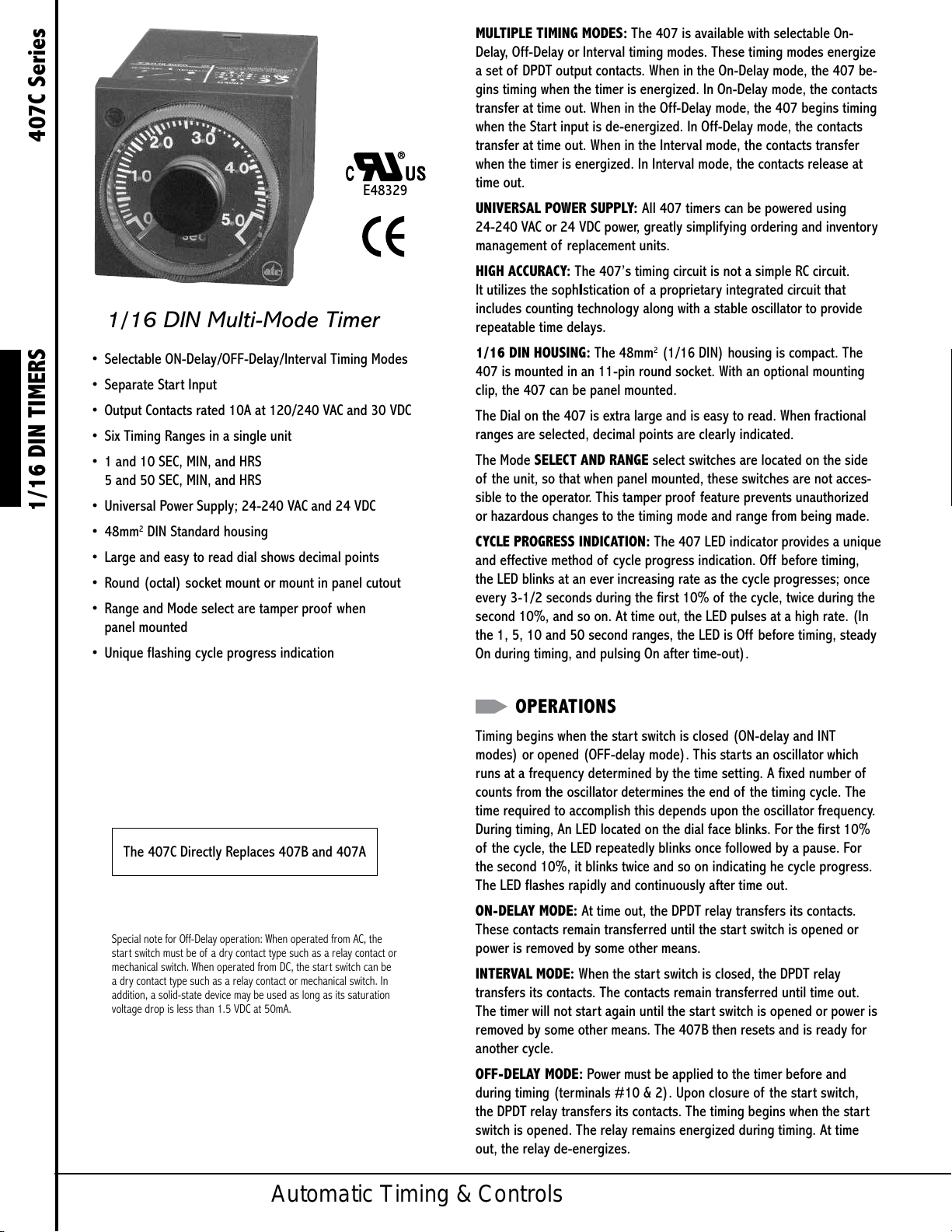
1/16 DIN Multi-Mode Timer
• Selectable ON-Delay/OFF-Delay/Interval Timing Modes
• Separate Start Input
• Output Contacts rated 10A at 120/240 VAC and 30 VDC
• Six Timing Ranges in a single unit
• 1 and 10 SEC, MIN, and HRS
5 and 50 SEC, MIN, and HRS
1/16 DIN TIMERS 407C Series
• Universal Power Supply; 24-240 VAC and 24 VDC
• 48mm2 DIN Standard housing
• Large and easy to read dial shows decimal points
• Round (octal) socket mount or mount in panel cutout
• Range and Mode select are tamper proof when
panel mounted
• Unique flashing cycle progress indication
E48329
MULTIPLE TIMING MODES: The 407 is available with selectable On-
Delay, Off-Delay or Interval timing modes. These timing modes energize
a set of DPDT output contacts. When in the On-Delay mode, the 407 be-
gins timing when the timer is energized. In On-Delay mode, the contacts
transfer at time out. When in the Off-Delay mode, the 407 begins timing
when the Start input is de-energized. In Off-Delay mode, the contacts
transfer at time out. When in the Interval mode, the contacts transfer
when the timer is energized. In Interval mode, the contacts release at
time out.
UNIVERSAL POWER SUPPLY: All 407 timers can be powered using
24-240 VAC or 24 VDC power, greatly simplifying ordering and inventory
management of replacement units.
HIGH ACCURACY: The 407’s timing circuit is not a simple RC circuit.
It utilizes the sophIstication of a proprietary integrated circuit that
includes counting technology along with a stable oscillator to provide
repeatable time delays.
1/16 DIN HOUSING: The 48mm2 (1/16 DIN) housing is compact. The
407 is mounted in an 11-pin round socket. With an optional mounting
clip, the 407 can be panel mounted.
The Dial on the 407 is extra large and is easy to read. When fractional
ranges are selected, decimal points are clearly indicated.
The Mode SELECT AND RANGE select switches are located on the side
of the unit, so that when panel mounted, these switches are not acces-
sible to the operator. This tamper proof feature prevents unauthorized
or hazardous changes to the timing mode and range from being made.
CYCLE PROGRESS INDICATION: The 407 LED indicator provides a unique
and effective method of cycle progress indication. Off before timing,
the LED blinks at an ever increasing rate as the cycle progresses; once
every 3-1/2 seconds during the first 10% of the cycle, twice during the
second 10%, and so on. At time out, the LED pulses at a high rate. (In
the 1, 5, 10 and 50 second ranges, the LED is Off before timing, steady
On during timing, and pulsing On after time-out).
The 407C Directly Replaces 407B and 407A
Special note for Off-Delay operation: When operated from AC, the
start switch must be of a dr y contact type such as a relay contact or
mechanical switch. When operated from DC, the start switch can be
a dry contact type such as a relay contact or mechanical switch. In
addition, a solid-state device may be used as long as its saturation
voltage drop is less than 1.5 VDC at 50mA.
OPERATIONS
Timing begins when the start switch is closed (ON-delay and INT
modes) or opened (OFF-delay mode). This starts an oscillator which
runs at a frequency determined by the time setting. A fixed number of
counts from the oscillator determines the end of the timing cycle. The
time required to accomplish this depends upon the oscillator frequency.
During timing, An LED located on the dial face blinks. For the first 10%
of the cycle, the LED repeatedly blinks once followed by a pause. For
the second 10%, it blinks twice and so on indicating he cycle progress.
The LED flashes rapidly and continuously after time out.
ON-DELAY MODE: At time out, the DPDT relay transfers its contacts.
These contacts remain transferred until the start switch is opened or
power is removed by some other means.
INTERVAL MODE: When the start switch is closed, the DPDT relay
transfers its contacts. The contacts remain transferred until time out.
The timer will not start again until the start switch is opened or power is
removed by some other means. The 407B then resets and is ready for
another cycle.
OFF-DELAY MODE: Power must be applied to the timer before and
during timing (terminals #10 & 2). Upon closure of the start switch,
the DPDT relay transfers its contacts. The timing begins when the start
switch is opened. The relay remains energized during timing. At time
out, the relay de-energizes.
Automatic Timing & Controls
Page 2
SPECIFICATIONS SPECIFICATIONS (CONTINUED)
MODELS 407C100F3X ON-Delay, OFF-Delay, Interval
Timing with (1) DPDT relay
(1 or 10 SEC/MIN/HRS)
407C500F3X ON-Delay, OFF-Delay, Interval
Timing with (1) DPDT relay
(5 or 50 SEC/MIN/HRS)
Both models available in 6 ranges from 1 SEC to
10 HRS or 5 SEC to 50 HRS
CONTACT Rated 10 AMPS resistive at 30 VDC or 250 VAC
RATING (or less) 1/8 HP @120 VAC 1/4 HP @ 240 VAC,
240 VA @ 240 VAC
LIFE: 10 million operation with no load
100,000 operations with:
10 AMPS at 30 VDC (or less) or
10 AMPS at 250 VAC (or less)
CONTACT Silver Nickel
MATERIAL
TEMPERATURE 0° to 122°F (-18°C to 50°C)
RATING
MOUNTING Plug-in 11-Pin round base
Options: Surface mounting socket
DIN rail mounting socket
Panel-mounting adapter kit
Plug-on socket kit
POWER Universal power supply - reverse polarity protected
REQUIREMENTS Unit will accept power from 24 to 240 VAC, 50 or
60 Hz, (+10%, -20%) 24 VDC (+20%, -20%)
AC Inrush - 1.5 Amps
Power required - 1.2 watts
DC Maximum ripple @ 100 Hz - 5%
Current required - 50mA
Power required - 1.2 watts
F option - Peak inrush current
= 2 AMPS @ 24 VDC
N option - Peak inrush current
= 150 mA @ 24 VDC
REPEAT Varies as a function of temperature.
ACCURACY Any voltage (constant temperature): –0.5%*
Any voltage (0 F to 140 F): –2.0%*
*Variation from average actual time.
MINIMUM 2% of range, with the exception of
SETTING 50 mSEC on the 1 second range
SETTING ACCURACY ±5% of range
RESET a 0 to 20 mSEC power interruption:
guaranteed no reset.
b 20 to 65 mSEC; it may reset (40
mSEC typical reset).
c Over 65 mSEC guaranteed to reset.
The TDR will reset properly and not start
timing when subjected to an open start
switch leakage of 1.5 mA or less.
(Prox switch & Triac drive applications)
TERMINAL #6 DC Minimum Current Rating - 50mA
(START SWITCH Maximum saturated voltage drop -
REQUIREMENTS 1.5 VDC
OFF-DELAY) AC Minimum Current Rating - 1.5 A
WEIGHT 5 oz. (140 g)
MODEL NUMBER
MODEL 407C 3
NUMBER
RANGE
Six dial-selected ranges 100
(1 or 10 SEC/MIN/HRS)
Six dial-selected ranges 500
(5 or 50 SEC/MIN/HRS)
VOLTAGE & FREQUENCY
12 VDC E
24 to 240 VAC (50/60 Hz) F
and 24 VDC
24 VDC (low inrush current for N
short-circuit protected sensors)
ARRANGEMENT
11-pin ON -Delay, OFF-Delay, 3
Interval Timing Modes
FEATURES
Standard X
Special K
ACCESSORIES
11-Pin surface/DIN rail socket 000-825-86-00
Hold down for above socket 405-025-07-00
(Requires 2 per unit)
Panel mounting bracket 405-320-02-00
Plug-in socket kit (11-pin) 314-260-07-00
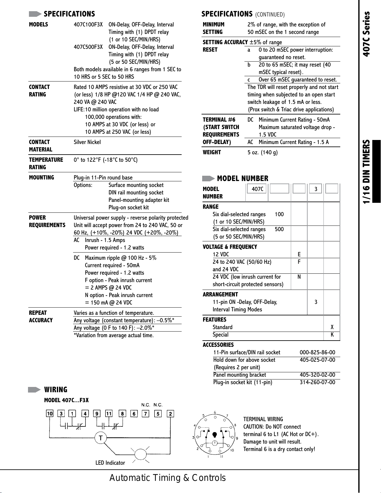
WIRING
MODEL 407C...F3X
1/16 DIN TIMERS 407C Series
LED Indicator
Automatic Timing & Controls
TERMINAL WIRING
CAUTION: Do NOT connect
terminal 6 to L1 (AC Hot or DC+).
Damage to unit will result.
Terminal 6 is a dry contact only!
Page 3

DIMENSIONS (INCHES/MILLIMETERS)
Optional 11-pin Socket
Part Number 000-825-96-00
1/16 DIN TIMERS 407C Series
TYPICAL CIRCUITS
ON-DELAY (MODE SWITCH IN ON-DELAY POSITION)
INTERVAL (MODE SWITCH IN INTERVAL POSITION)
OFF-DELAY (MODE SWITCH IN OFF-DELAY POSITION)
*START/RESET
*in off-delay mode, start switch must be isolated.
Do NOT connect any load in parallel
BEFORE START
TIMING
TIMED OUT
O O X O = LOAD OFF
X = LOAD ON
Powered by TCPDF (www.tcpdf.org)Powered by TCPDF (www.tcpdf.org)
Powered by TCPDF (www.tcpdf.org)Powered by TCPDF (www.tcpdf.org)
Automatic Timing & Controls
 Loading...