

Page 1
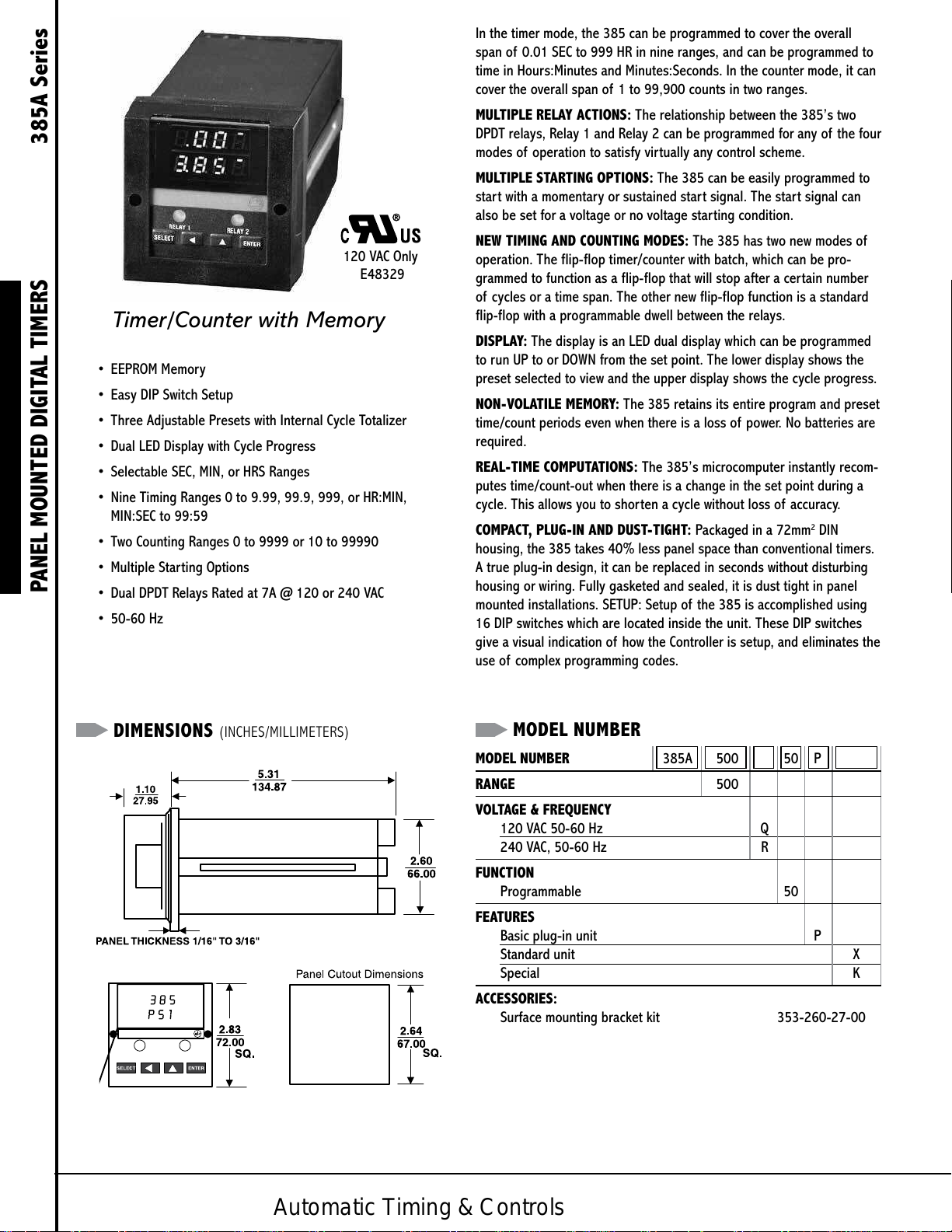
Timer/Counter with Memory
• EEPROM Memory
• Easy DIP Switch Setup
• Three Adjustable Presets with Internal Cycle Totalizer
• Dual LED Display with Cycle Progress
• Selectable SEC, MIN, or HRS Ranges
• Nine Timing Ranges 0 to 999, 999, 999, or HR:MIN,
MIN:SEC to 99:59
• Two Counting Ranges 0 to 9999 or 10 to 99990
• Multiple Starting Options
PANEL MOUNTED DIGITAL TIMERS 385A Series
• Dual DPDT Relays Rated at 7A @ 120 or 240 VAC
• 50-60 Hz
120 VAC Only
E48329
In the timer mode, the 385 can be programmed to cover the overall
span of 001 SEC to 999 HR in nine ranges, and can be programmed to
time in Hours:Minutes and Minutes:Seconds In the counter mode, it can
cover the overall span of 1 to 99,900 counts in two ranges
MULTIPLE RELAY ACTIONS: The relationship between the 385’s two
DPDT relays, Relay 1 and Relay 2 can be programmed for any of the four
modes of operation to satisfy virtually any control scheme
MULTIPLE STARTING OPTIONS: The 385 can be easily programmed to
start with a momentary or sustained start signal The star t signal can
also be set for a voltage or no voltage starting condition
NEW TIMING AND COUNTING MODES: The 385 has two new modes of
operation The flip-flop timer/counter with batch, which can be pro-
grammed to function as a flip-flop that will stop after a certain number
of cycles or a time span The other new flip-flop function is a standard
flip-flop with a programmable dwell between the relays
DISPLAY: The display is an LED dual display which can be programmed
to run UP to or DOWN from the set point The lower display shows the
preset selected to view and the upper display shows the cycle progress
NON-VOLATILE MEMORY: The 385 retains its entire program and preset
time/count periods even when there is a loss of power No batteries are
required
REAL-TIME COMPUTATIONS: The 385’s microcomputer instantly recom-
putes time/count-out when there is a change in the set point during a
cycle This allows you to shorten a cycle without loss of accuracy
COMPACT, PLUG-IN AND DUST-TIGHT: Packaged in a 72mm
housing, the 385 takes 40% less panel space than conventional timers
A true plug-in design, it can be replaced in seconds without disturbing
housing or wiring Fully gasketed and sealed, it is dust tight in panel
mounted installations SETUP: Setup of the 385 is accomplished using
16 DIP switches which are located inside the unit These DIP switches
give a visual indication of how the Controller is setup, and eliminates the
use of complex programming codes
2
DIN
DIMENSIONS (INCHES/MILLIMETERS)
MODEL NUMBER
MODEL NUMBER 385A 500 50 P
RANGE 500
VOLTAGE & FREQUENCY
120 VAC 50-60 Hz Q
240 VAC, 50-60 Hz R
FUNCTION
Programmable 50
FEATURES
Basic plug-in unit P
Standard unit X
Special K
ACCESSORIES:
Surface mounting bracket kit 353-260-27-00
Automatic Timing & Controls
Page 2
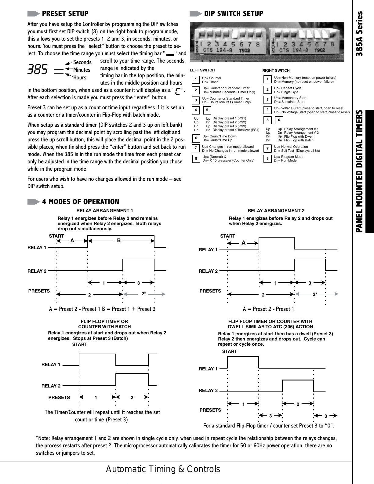
PRESET SETUP DIP SWITCH SETUP
Dn= X 10 prescaler (Counter Only)
t, close to reset)
Dn= Run Mode
LEFT SWITCH
RIGHT SWITCH
RELA
RELA
RELAY ARRANGEMENT 1
RELA
RELA
RELAY ARRANGEMENT 2
1 2
RELA
RELA
FLIP FLOP TIMER OR
2
RELA
RELA
FLIP FLOP TIMER OR COUNTER WITH
After you have setup the Controller by programming the DIP switches
you must first set DIP switch (8) on the right bank to program mode,
this allows you to set the presets 1, 2 and 3, in seconds, minutes, or
hours You must press the “select” button to choose the preset to se-
lect To choose the time range you must select the timing bar ” “ and
Seconds
385
Minutes
Hours
in the bottom position, when used as a counter it will display as a “ ”
After each selection is made you must press the “enter” button
Preset 3 can be set up as a count or time input regardless if it is set up
as a counter or a timer/counter in Flip-Flop with batch mode
When setup as a standard timer (DIP switches 2 and 3 up on left bank)
you may program the decimal point by scrolling past the left digit and
press the up scroll button, this will place the decimal point in the 2 pos-
sible places, when finished press the “enter” button and set back to run
mode When the 385 is in the run mode the time from each preset can
only be adjusted in the time range with the decimal position you chose
while in the program mode
For users who wish to have no changes allowed in the run mode – see
DIP switch setup
scroll to your time range The seconds
range is indicated by the
timing bar in the top position, the min-
utes in the middle position and hours
Up= Counter
1
Dn= Timer
Up= Counter or Standard Timer
2
Dn= Minutes:Seconds (Timer Only)
Up= Counter or Standard Timer
3
Dn= Hours:Minutes (Timer Only)
4 5
Up Up
Up Dn
Dn Up
Dn Dn
Display preset 1 (PS1)
Display preset 2 (PS2)
Display preset 3 (PS3)
Display preset 4 Totalizer (PS4)
Up= Count/Time Down
6
Dn= Count/Time Up
Up= Changes in run mode allowed
7
Dn= No Changes in run mode allowed
Up= (Normal) X 1
8
Up= Non-Memory (reset on power failure)
1
Dn= Memory (no reset on power failure)
Up= Repeat Cycle
2
Dn= Single Cyle
Up= Momentary Start
3
Dn= Sustained Start
Up= Voltage Start (close to start, open to reset)
4
Dn= No Voltage Start (open to star
5 6
Up Up
Up Dn
Dn Up
Dn Dn
Relay Arrangement # 1
Relay Arrangement # 2
Flip Flop with Dwell
Flip Flop with Batch
Up= Normal Operation
7
Dn= Self Test (Displays all 8’s)
Up= Program Mode
8
4 MODES OF OPERATION
Relay 1 energizes before Relay 2 and remains
energized when Relay 2 energizes. Both relays
drop out simultaneously.
START
Y 1
Y 2
PRESETS
A = Preset 2 - Preset 1 B = Preset 1 + Preset 3
Relay 1 energizes at start and drops out when Relay
energizes. Stops at Preset 3 (Batch)
A B
COUNTER WITH BATCH
START
Y 1
Relay 1 energizes before Relay 2 and drops out
when Relay 2 energizes.
START
PANEL MOUNTED DIGITAL TIMERS 385A Series
A
Y 1
Y 2
1
2
3
2*
PRESETS
1
2
3
2*
A = Preset 2 - Preset 1
DWELL SIMILAR TO ATC (306) ACTION
Relay 1 energizes at start then has a dwell (Preset 3)
Relay 2 then energizes and drops out. Cycle can
repeat or cycle once.
START
Y 1
Y 2
PRESETS
The Timer/Counter will repeat until it reaches the set
count or time (Preset 3)
Y 2
PRESETS
1 2
3
3
For a standard Flip-Flop timer / counter set Preset 3 to “0"
*Note: Relay arrangement 1 and 2 are shown in single cycle only, when used in repeat cycle the relationship between the relays changes,
the process restarts after preset 2 The microprocessor automatically calibrates the timer for 50 or 60Hz power operation, there are no
switches or jumpers to set
Automatic Timing & Controls
Page 3

OPERATION
THE DISPLAY: A highly visible dual display consists of three
digits with a movable decimal point or four digits for counting
There is a horizontal timing bar “ ” which appears to the
right of the upper display and blinks once per second during
timing This is very useful in showing that the timer is timing
especially when the digits do not change rapidly as in the hours
ranges The timing bar blinks rapidly at time-out as well The
lower display is DIP switch selectable to display the preset time
or counts for any one of the four presets, and the upper display
will show that presets cycle progress
UNDERSTANDING THE PRESETS: There are three program-
mable presets, Preset 1, Preset 2, and Preset 3 There is a
totalizer for each mode of operation, this preset is designated
Preset 4 This preset is for display only and increments a count
at the end of each cycle, to reset the totalizer to zero you must
go into programming mode (see DIP SWITCH SETUP) and set all
four digits to zero Once the totalizer reaches 9999 it will go to
E000, the maximum count is E999 which actually has a count
value of 10999 When changing or setting a preset in run mode,
the display will revert back to the running time after a button
has not been used for 10 seconds
PANEL MOUNTED DIGITAL TIMERS 385A Series
FUNCTIONS: To use the 385 you must apply power to terminals
16 and 2, terminal 1 is the start/reset or momentary start input
terminal You must also apply voltage to terminal 15 (clock/count
input) to start timing or place a count, if power is removed from
terminal 15 when you are timing the 385 will stop where it is
and continue when power is reapplied to terminal 15 The 385
was designed to replace most of the functions of the ATC model
375 Most of these functions can be done with the relay arrange-
ment 1 and 2 modes of operation The arrangement 3 mode was
not implemented, and most arrangement 3 applications can be
done with the flip-flop mode of operation The 385 can function
as a ON-Delay or OFF-Delay timer or counter in arrangement 1,
(ATC model 365, 366) to allow this, preset 1 and preset 3 must
be set to 999 hours, the 385 will interpret this as infinite time
and display as “INF” Preset 2 will be the set time and allow a
setting of 999 hours Relay 1 will act as an instantaneous relay,
and Relay 2 as a delayed relay The 385 when set as a standard
timer operates in hours, minutes, and seconds with a movable
decimal point, also the 385 can operate in hours:minutes and
minutes:seconds with a maximum setting of 99:59 (see DIP
SWITCH SETUP)
NEW MODES OF OPERATION: The 385 can perform as a Flip-Flop
timer or counter with batch Preset 1 is the first set time and Pre-
set 2 is the second set time Preset 3 is the batch, which it stops
at after a certain number of flip-flop cycles up to 999, or stops at
any desired time In this mode you cannot use the hours:minutes
and minutes:seconds operation The other new mode of opera-
tion is the Flip-Flop timer or counter with dwell This is the mode
to be used when a standard Flip-Flop is needed This new mode
is designed to have a first set time (Preset 1) then a dwell time
(Preset 3) followed by the second set time (Preset 2), when used
in repeat cycle there is a dwell after Preset 2 also To use as a
standard Flip-Flop set the dwell time to “0” All of the modes can
be set for a voltage or no voltage start, momentary or sustained
start, and repeat or single cycles
Automatic Timing & Controls
Page 4

WIRING
Supply
L1 to Power
L2 (common)
8 6 7 9 14 10 16 2 1 15 3 4 5 13 11 12
Power
Supply
Enable
L1 to Start /
Reset
L1 to clock/
count
Relay 2Relay 1
Clock
TERMINAL WIRING
14 13 12 11 10 9 8
REAR OF HOUSING
WHEN
PANEL MOUNTED
*
The start switch can be a voltage or no voltage
start and can be sustained or momentary.
1 2 3 4 5 6 15
L2
Start*
Integrate Time or
Pulse to Count
7
16
L1
PANEL MOUNTED DIGITAL TIMERS 385A Series
Powered by TCPDF (www.tcpdf.org)Powered by TCPDF (www.tcpdf.org)Powered by TCPDF (www.tcpdf.org)
Powered by TCPDF (www.tcpdf.org)Powered by TCPDF (www.tcpdf.org)
Automatic Timing & Controls
 Loading...