

Page 1
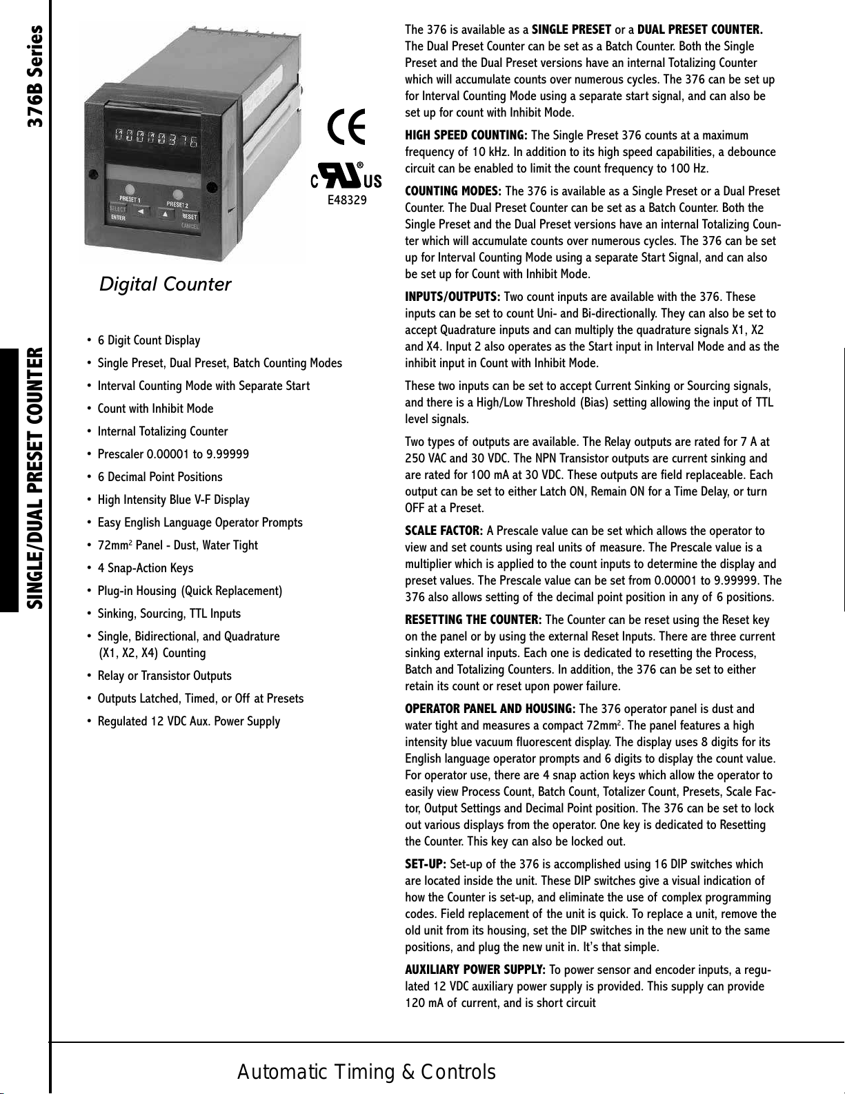
Digital Counter
• 6 Digit Count Display
• Single Preset, Dual Preset, Batch Counting Modes
• Interval Counting Mode with Separate Start
• Count with Inhibit Mode
• Internal Totalizing Counter
• Prescaler 0.00001 to 9.99999
• 6 Decimal Point Positions
• High Intensity Blue V-F Display
• Easy English Language Operator Prompts
• 72mm2 Panel - Dust, Water Tight
• 4 Snap-Action Keys
• Plug-in Housing (Quick Replacement)
SINGLE/DUAL PRESET COUNTER 376B Series
• Sinking, Sourcing, TTL Inputs
• Single, Bidirectional, and Quadrature
(X1, X2, X4) Counting
• Relay or Transistor Outputs
• Outputs Latched, Timed, or Off at Presets
• Regulated 12 VDC Aux. Power Supply
E48329
The 376 is available as a SINGLE PRESET or a DUAL PRESET COUNTER.
The Dual Preset Counter can be set as a Batch Counter. Both the Single
Preset and the Dual Preset versions have an internal Totalizing Counter
which will accumulate counts over numerous cycles. The 376 can be set up
for Interval Counting Mode using a separate start signal, and can also be
set up for count with Inhibit Mode.
HIGH SPEED COUNTING: The Single Preset 376 counts at a maximum
frequency of 10 kHz. In addition to its high speed capabilities, a debounce
circuit can be enabled to limit the count frequency to 100 Hz.
COUNTING MODES: The 376 is available as a Single Preset or a Dual Preset
Counter. The Dual Preset Counter can be set as a Batch Counter. Both the
Single Preset and the Dual Preset versions have an internal Totalizing Coun-
ter which will accumulate counts over numerous cycles. The 376 can be set
up for Interval Counting Mode using a separate Start Signal, and can also
be set up for Count with Inhibit Mode.
INPUTS/OUTPUTS: Two count inputs are available with the 376. These
inputs can be set to count Uni- and Bi-directionally. They can also be set to
accept Quadrature inputs and can multiply the quadrature signals X1, X2
and X4. Input 2 also operates as the Start input in Interval Mode and as the
inhibit input in Count with Inhibit Mode.
These two inputs can be set to accept Current Sinking or Sourcing signals,
and there is a High/Low Threshold (Bias) setting allowing the input of TTL
level signals.
Two types of outputs are available. The Relay outputs are rated for 7 A at
250 VAC and 30 VDC. The NPN Transistor outputs are current sinking and
are rated for 100 mA at 30 VDC. These outputs are field replaceable. Each
output can be set to either Latch ON, Remain ON for a Time Delay, or turn
OFF at a Preset.
SCALE FACTOR: A Prescale value can be set which allows the operator to
view and set counts using real units of measure. The Prescale value is a
multiplier which is applied to the count inputs to determine the display and
preset values. The Prescale value can be set from 0.00001 to 9.99999. The
376 also allows setting of the decimal point position in any of 6 positions.
RESETTING THE COUNTER: The Counter can be reset using the Reset key
on the panel or by using the external Reset Inputs. There are three current
sinking external inputs. Each one is dedicated to resetting the Process,
Batch and Totalizing Counters. In addition, the 376 can be set to either
retain its count or reset upon power failure.
OPERATOR PANEL AND HOUSING: The 376 operator panel is dust and
water tight and measures a compact 72mm2. The panel features a high
intensity blue vacuum fluorescent display. The display uses 8 digits for its
English language operator prompts and 6 digits to display the count value.
For operator use, there are 4 snap action keys which allow the operator to
easily view Process Count, Batch Count, Totalizer Count, Presets, Scale Fac-
tor, Output Settings and Decimal Point position. The 376 can be set to lock
out various displays from the operator. One key is dedicated to Resetting
the Counter. This key can also be locked out.
SET-UP: Set-up of the 376 is accomplished using 16 DIP switches which
are located inside the unit. These DIP switches give a visual indication of
how the Counter is set-up, and eliminate the use of complex programming
codes. Field replacement of the unit is quick. To replace a unit, remove the
old unit from its housing, set the DIP switches in the new unit to the same
positions, and plug the new unit in. It’s that simple.
AUXILIARY POWER SUPPLY: To power sensor and encoder inputs, a regu-
lated 12 VDC auxiliary power supply is provided. This supply can provide
120 mA of current, and is short circuit
Automatic Timing & Controls
Page 2
OPERATION
The Series 376 Preset Counter is a predetermining counter that will
count high speed unidirectional, bi-directional, or quadrature input
signals, and will activate an output when the predetermined preset
value is reached. The unit is available in both Single and Dual Preset
models, and includes an internal totalizer. Also, the 376 counter
will operate as a Batch Counter using the second preset as a Batch
Preset. The Series 376 comes with a variety of counting modes. The
operation of each counting mode is described below.
COUNT UP FROM ZERO TO A GIVEN PRESET: The Output in the Coun-
ter is activated when the Count equals the Preset. In the Dual Preset
Model, the Counter counts up from zero and Output 1 is activated
when Preset 1 is reached and Output 2 is activated when Preset 2 is
reached.
COUNT DOWN FROM A PRESET TO ZERO: When Reset is pressed, the
Counter is set to the Preset Value. When the Count Value equals zero,
the Output is activated. In the Dual Preset Model, the Counter counts
down from the High Preset value and activates one Output when it
reaches the Low Preset Value; the other Output is activated when the
Counter counts down from the Low Preset Value and reaches zero.
INTERVAL MODE: In this mode, the Counter will not begin counting
until Input 2 is turned ON, indicating a Start Signal. Once the Start
Signal is received, the Output will turn ON and the Counter will count.
The Out- put will then turn OFF at the preset or zero. The Start Signal
must be activated each time the process is reset, even when the
Counter is set to Auto Reset
BATCH MODE - DUAL PRESET MODELS ONLY: In the Batch Mode, In-
put 1 is the Count input and will turn ON at Preset 1. Each time Output
1 turns ON, the Batch Counter will record a count. When the Batch
Counter value equals the value in Preset 2, Output 2 will turn ON. The
Batch Mode must be Manually Reset (unless T2 is set to 00.00 (.5 w/
AR) for Auto Reset).
TIMED OUTPUTS: The Outputs can be delayed before turning OFF by
setting time delay values for each output. Once the Preset is reached,
a time delay, according to the time value set, will occur before the
outputs turn OFF. This value can range from 0.00 SEC (OFF at Preset)
to 99.99 SEC (Latched ON). In addition, the outputs can also be set
to turn OFF upon reaching the preset for the other output in the Dual
Preset Model.
SCALE FACTOR: A Prescale value can be set to allow viewing and
setting counts using real units of measure. The Prescale value is a
multiplier which is applied to the count in-put(s) to determine the
count display and preset values. The Prescale value can be set from
0.00001 to 9.99999. In addition, the decimal point can be set on the
display to any one of 6 positions.
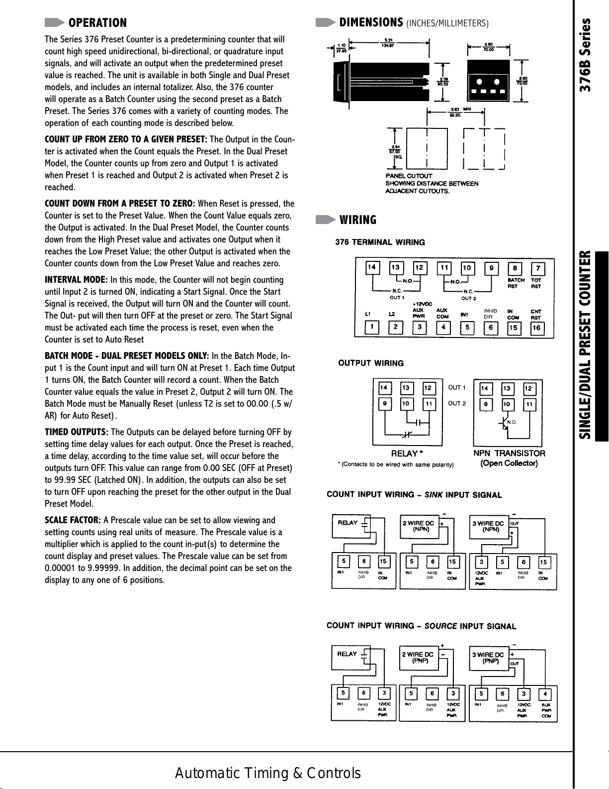
DIMENSIONS (INCHES/MILLIMETERS)
WIRING
SINGLE/DUAL PRESET COUNTER 376B Series
Automatic Timing & Controls
Page 3
SPECIFICATIONS
MODELS Single and Dual Preset with either NPN
(Solid State) or Relay Outputs.
COUNT INPUT Bi-Directional
MODES Quadrature X1
(SWITCH Quadrature X2
SELECTABLE) Quadrature X4
Count with Inhibit
Interval with Start Input
SETTINGS Presets 1 to 999,999
(FRONT OF Scale Factor 0.00001 to 9.99999
PANELS) Timed Outputs 00.01 to 99.98 SEC
Latched
Off at Preset
Decimal Position 0 to 6
OPERATING Count Up or Count Down
FEATURES Count/Go or Count/Stop
(SWITCH Sink or Source Count Input
SELECTABLE) High or Low Threshold (Bias)
Auto Reset at High preset (Count Up)
Zero (Count Down)
After Timed Output
Totalizer
Dual Preset/Batch mode
Security lockout Access to Presets
Access to T1, T2, SF, DP
Front panel Reset
Reset on Power Up
COUNT Sink - 9.4K ohm pull up
INPUTS Max. current = 1.25 mA
Source - 4.7K ohm pull down
Max. voltage = 30 VDC, @ 7 mA
High Bias ViL = 5.5 V Max.
SINGLE/DUAL PRESET COUNTER 376B Series
ViH = 7.5 V Min.
Low Bias ViL = 1.5 V Max.
ViH = 3.75 V Min.
Debounce - reduces count Input 1 to 100 Hz
(Input 2 no debounce.)
Interval start requires 15 mSEC minimum pulse.
(Can be momentary or sustained.)
MAXIMUM 10 kHz Count Up Mode
COUNTING 9 kHz Count Down Mode
FREQUENCY Reduce by 3 kHz when Totalizing Counter is enabled
Reduce by 2 kHz when Auto Reset is enabled
Min. pulse 10 μSEC on; 90 μSEC off.
REMOTE Count, Batch, Totalizer
RESETS Min. 15 mSEC pulse
Pulled to 5V via 8K ohm res.
Active Low. ViL = 0.5V Max.
Max. current = .625 mA.
OUTPUT - Current Sinking
SOLID STATE I sink = 100 mA Max.
VoL = 1.0 VDC Max.
Max. Voltage = 30 VDC
OUTPUT - Life 100 million operations (no load)
RELAY Contact Rating 7 amp @ 30 VDC or 250 VAC,
1/4 HP
DC SUPPLY 12 VDC Regulated, ±4% Max. current = 120 mA
MEMORY Non Volatile EEPROM
230,000 Power Losses MIN
10 Year Retention
DISPLAY 8 Digit, 14 Segment
5 mm x 4.1 mm
Blue Vacuum Fluorescent
OPERATING 0° F to 140° F
TEMPERATURE
HUMIDITY 0% to 80% RH Non-condensing
POWER 120 VAC 95 - 132 VAC
REQUIREMENTS 240 VAC 190 - 264 VAC 50 / 60 Hz
Max. Power = 8 VA
TERMINALS 16 screw terminals located accessible from rear
HOUSING Plug in, 72mm2 DIN
Fully Gasketed, Dust and Watertight.
WEIGHT 1.47 lbs. SHIP 2.0 lbs.
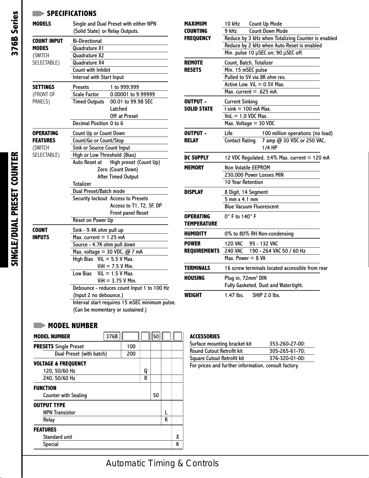
MODEL NUMBER
MODEL NUMBER 376B 50
PRESETS Single Preset 100
Dual Preset (with batch) 200
VOLTAGE & FREQUENCY
120, 50/60 Hz Q
240, 50/60 Hz R
FUNCTION
Counter with Sealing 50
OUTPUT TYPE
NPN Transistor L
Relay R
FEATURES
Standard unit X
Special K
Automatic Timing & Controls
ACCESSORIES
Surface mounting bracket kit 353-260-27-00:
Round Cutout Retrofit kit 305-265-61-70:
Square Cutout Retrofit kit 376-320-01-00:
For prices and further information, consult factory.
Page 4
SETTING THE COUNTER
To set the Counter, there are four push-button keys located on the
front of the unit. These buttons are provided to allow the user to
select, change and save various values. These key operations are
dependent on the DIP Switch settings of the unit (see below).
In addition to the normal counting modes of the unit, the 376B has
the capability of operating as a Batch Counter and a Totalizer Counter.
When these modes are activated, the functions of the Counter change
accordingly. Pressing the RESET key, with the Count, Batch, or Total-
izer value displayed, will reset that value.
This figure shows the front of panel with the Process Count value
displayed. Pressing SELECT will scroll through a menu of options.
After one of these options is
displayed for a second, the
value for this option is automati-
cally displayed. Once the option
value is displayed, pressing the
< key will move one digit to the
left and the ^ key will increment
the value by one. Then the
SELECT key must be pressed to save the new value. Pressing RESET
will return to the Process Count display. If SELECT is not pressed after
a change, RESET will return to the count display and the change will
not be entered.
Selections in addition to Process Count are:
Totalizer - counts accumulated since last
Totalizer Reset. When the total counts exceed
00000376
99,999,999 the Totalizer will blink Pressing
RESET will scroll through the actual value, pressing RESET a final
time will reset the value to zero.
Batch - number of cycles elapsed in Batch
B 1
Mode.
Preset 1/Preset 2 - value compared with
the actual count. When the Preset Value is
000500
displayed, the Preset LED on the panel will light, indicating which
preset is displayed.
Prescale - this factor will scale the input
counts. The count signal is multiplied by the
1.00000
prescale value to determine the count display. The prescale value
can range from 0.00001 to 9.99999.
NOTE: If the prescale value is greater than 1, the out put will
energize when the count value passes the preset value. Output 1/
Output 2 - time delay setting for outputs.
Decimal - the number of decimal positions for
LATCHED
the display.
When the Counter reaches its Presets, the
DP 0
Outputs will activate and the LEDs on the panel
will flash, indicating which output is activated.
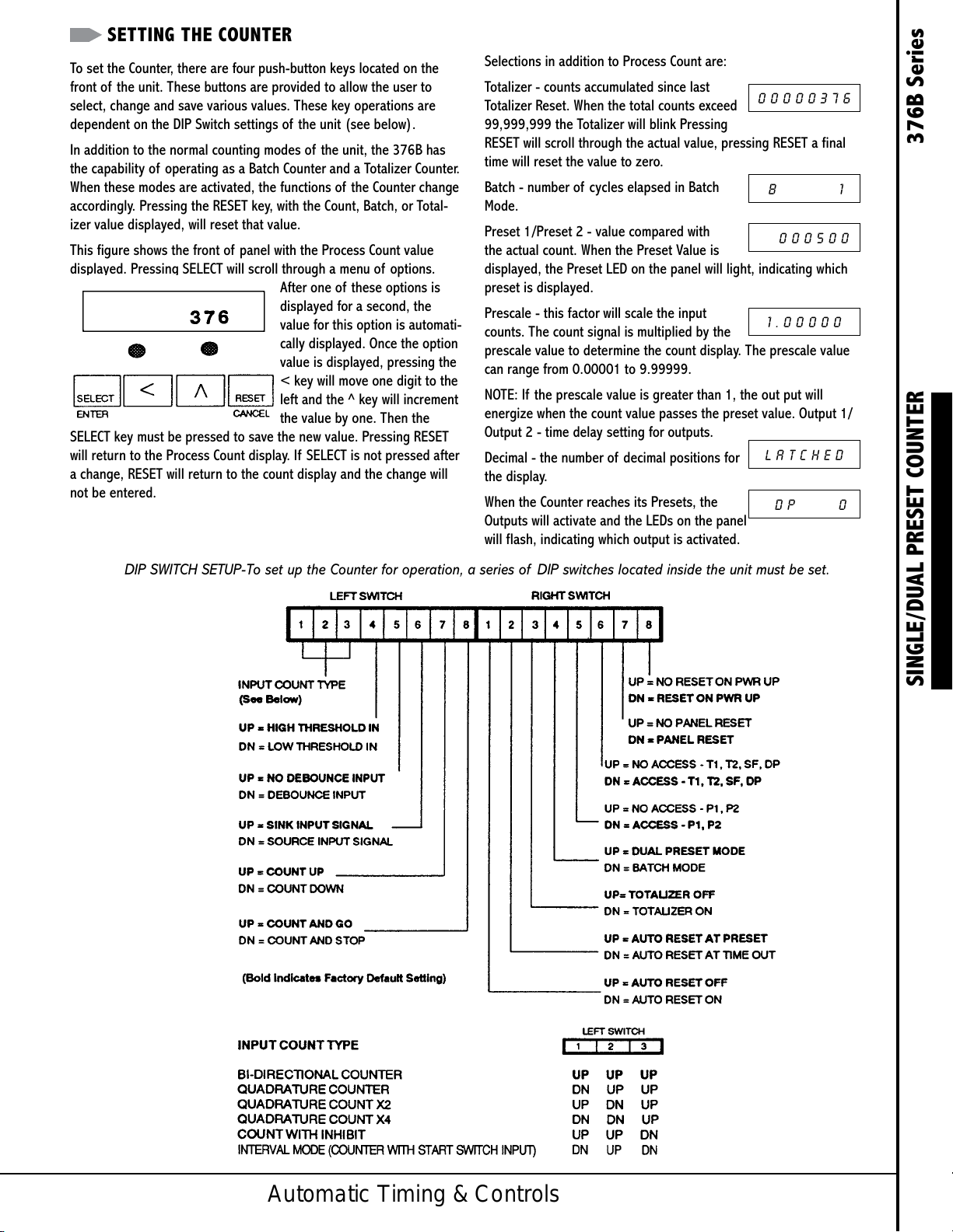
DIP SWITCH SETUP-To set up the Counter for operation, a series of DIP switches located inside the unit must be set.
SINGLE/DUAL PRESET COUNTER 376B Series
Powered by TCPDF (www.tcpdf.org)Powered by TCPDF (www.tcpdf.org)Powered by TCPDF (www.tcpdf.org)
Powered by TCPDF (www.tcpdf.org)Powered by TCPDF (www.tcpdf.org)
Automatic Timing & Controls
 Loading...