

Page 1
Based on a powerful built-in microcomputer, the compact 366 is the most
versatile and cost-effective counter ATC has ever built. No industrial counter has
ever achieved a higher level of reliability and ruggedness than the 366. It has
no moving parts in its electronic logic circuits, only plug-in circuit boards which
are computer-tested for reliability and assembled virtually without hand wiring.
Its few mechanical components have been selected for reliable service; long
life relays with heavy-duty contacts and rotary set point selector switches with
extremely low wear characteristics.
CONTACT BOUNCE AND NOISE IMMUNITY: No industrial counter of-
fers greater immunity to noise and contact bounce than the 366. Most
noise encountered in typical industrial environments is blocked by such
design features as full-wave bridges and a transformer power supply... so
effectively that the 366 does not have to be shielded. Furthermore the
366’s microcomputer employs redundant sampling logic to detect and
reject any noise pulse that manages to penetrate its defenses. Through
the same powerful technique, the microcomputer also detects and rejects
even severe contact bounce. As a result, the 366 maintains absolute count
accuracy and is virtually immune to false starts and reset, even in difficult
industrial environments.
COMPUTATION: Through its internal microcomputer, the 366 keeps
track of the set point throughout the count cycle. Whenever there is
a change in set point, even during a cycle, it instantly recomputes the
remaining count and accurately determines the number of counts
before count-out. This unique capability is especially valuable in the count-
down modes as it allows you to shorten or lengthen a cycle
without loss of accuracy.
PROGRAMMABLE DISPLAY: The 366’s three-digit cycle progress display
will count UP to or DOWN from the set point, depending on the position
of an internal jumper. After count-out, the display will either STOP or GO.
In the UP & GO program, the display counts up to the set point and
continues to count after count-out; in the DOWN & GO mode, it counts
down to the set point, then begins to count up (from zero) after count-out.
WIDE RANGE: Each 366 Long-Ranger covers the overall span of 1 to
99,900 counts in three switch-selected ranges of 1 to 999, 10 to 9990
or 12 to 99,900. It can be optimized within any selected range simply by
removing appropriate selector knobs (e.g. with the counter in the 1 to
999 range, you can obtain a tamper-proof span of 1 to 99 by setting the
left selector at 0 and removing the knob.) To the right of the three-digit
display, a counting bar ( ) blinks on each time a pulse is received.
At left, a marker ( )turns on when the delayed relay is energized at
count-out.
SELF-DIAGNOSTICS: A built-in diagnostic program lets you verify—
without using any test instrument--that the counter’s functional circuits
are operating properly. Just follow the instructions on the flip-up card,
using the counter’s own display for the test readout. If all self-test
displays are correct, any malfunction is almost certainly due to
external circuits or to the relays, not the counter.
COMPACT, PLUG-IN AND DUST-TIGHT: Packaged in a 72mm2 DIN housing,
the 366 occupies 40% less panel space than most other industrial coun-
ters. It is a true plug-in counter that can be replaced in seconds without
disturbing housing or wiring. The 366 is also fully gasketed and O ring
sealed to be dust and water-tight whether panel or surface-mounted.
POSITIVE RESET TIME AND PULSE LENGTH: Digitally clocked by the
microcomputer, the 366’s reset time is consistently of the same duration,
regardless of variations in line voltage, power supply or cycle length.
When the 366 operates in repeat-cycle mode, the output pulse is also
digitally clocked so that both the time of occurrence and its duration are
consistent from cycle to cycle.
E48329
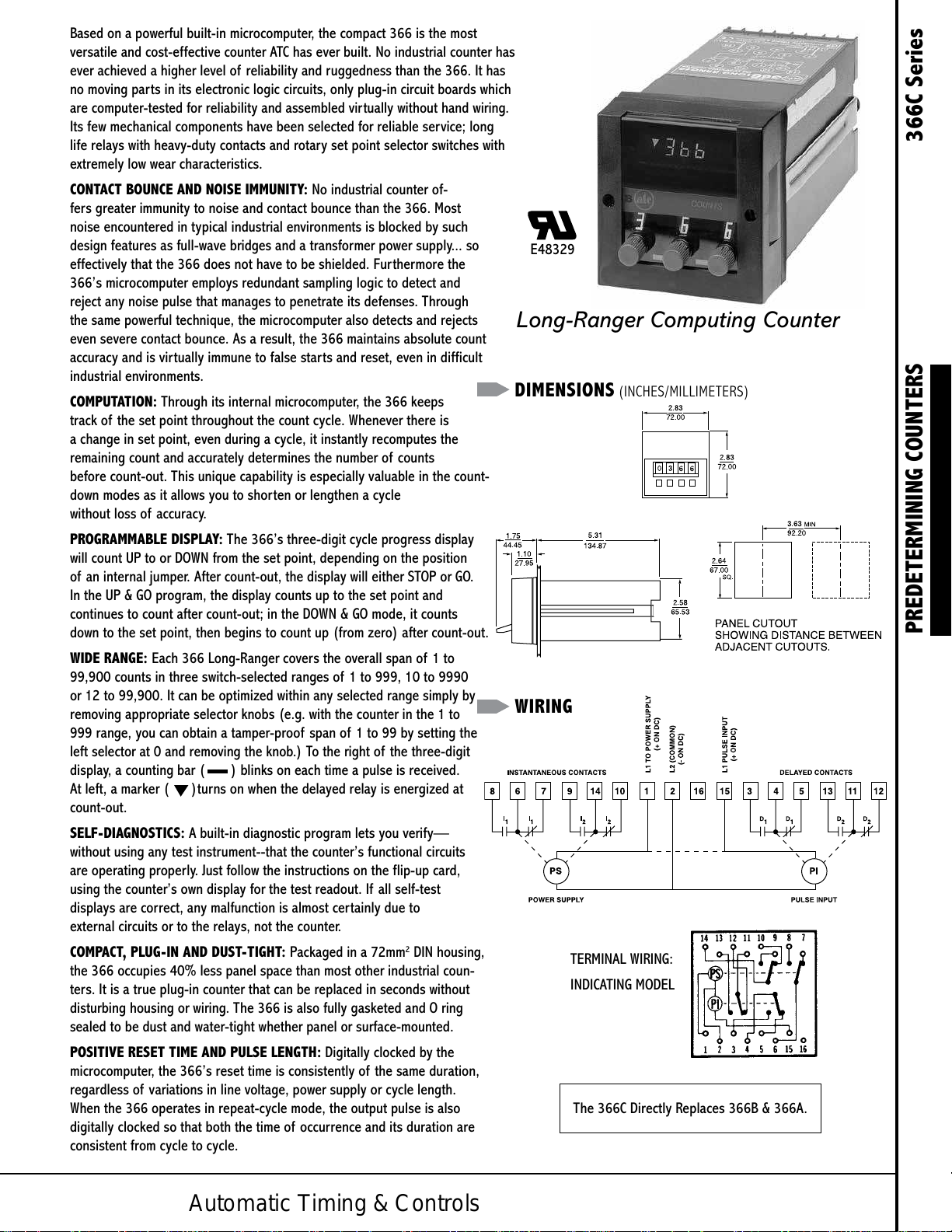
Long-Ranger Computing Counter
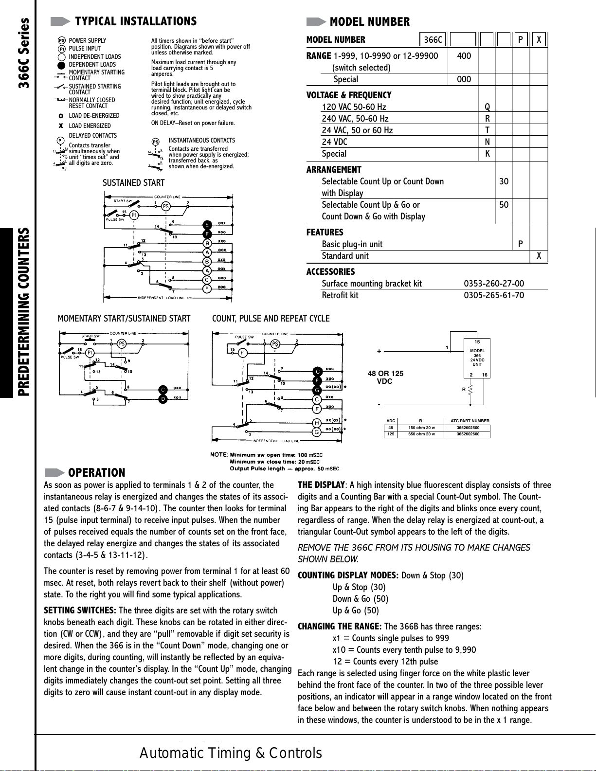
DIMENSIONS (INCHES/MILLIMETERS)
PREDETERMINING COUNTERS 366C Series
WIRING
TERMINAL WIRING:
INDICATING MODEL
The 366C Directly Replaces 366B & 366A.
Automatic Timing & Controls
Page 2
TYPICAL INSTALLATIONS
48 OR 125
NUMBER
MODEL NUMBER
POWER SUPPLY
PULSE INPUT
INDEPENDENT LOADS
DEPENDENT LOADS
MOMENTARY STARTING
CONTACT
SUSTAINED STARTING
CONTACT
NORMALLY CLOSED
RESET CONTACT
LOAD DE-ENERGIZED
LOAD ENERGIZED
DELAYED CONTACTS
Contacts transfer
simultaneously when
unit “times out” and
all digits are zero.
SUSTAINED START
All timers shown in “before star t”
position. Diagrams shown with power off
unless otherwise marked.
Maximum load current through any
load carrying contact is 5
amperes.
Pilot light leads are brought out to
terminal block. Pilot light can be
wired to show practically any
desired function; unit energized, cycle
running, instantaneous or delayed switch
closed, etc.
ON DELAY–Reset on power failure.
INSTANTANEOUS CONTACTS
Contacts are transferred
when power supply is energized;
transferred back, as
shown when de-energized.
MODEL NUMBER 366C P X
RANGE 1-999, 10-9990 or 12-99900 400
(switch selected)
Special 000
VOLTAGE & FREQUENCY
120 VAC 50-60 Hz Q
240 VAC, 50-60 Hz R
24 VAC, 50 or 60 Hz T
24 VDC N
Special K
ARRANGEMENT
Selectable Count Up or Count Down 30
with Display
Selectable Count Up & Go or 50
Count Down & Go with Display
FEATURES
Basic plug-in unit P
Standard unit X
ACCESSORIES
Surface mounting bracket kit 0353-260-27-00
Retrofit kit 0305-265-61-70
MOMENTARY START/SUSTAINED START COUNT, PULSE AND REPEAT CYCLE
PREDETERMINING COUNTERS 366C Series
OPERATION
As soon as power is applied to terminals 1 & 2 of the counter, the
instantaneous relay is energized and changes the states of its associ-
ated contacts (8-6-7 & 9-14-10). The counter then looks for terminal
15 (pulse input terminal) to receive input pulses. When the number
of pulses received equals the number of counts set on the front face,
the delayed relay energize and changes the states of its associated
contacts (3-4-5 & 13-11-12).
The counter is reset by removing power from terminal 1 for at least 60
msec. At reset, both relays rever t back to their shelf (without power)
state. To the right you will find some typical applications.
SETTING SWITCHES: The three digits are set with the rotary switch
knobs beneath each digit. These knobs can be rotated in either direc-
tion (CW or CCW), and they are “pull” removable if digit set security is
desired. When the 366 is in the “Count Down” mode, changing one or
more digits, during counting, will instantly be reflected by an equiva-
lent change in the counter’s display. In the “Count Up” mode, changing
digits immediately changes the count-out set point. Setting all three
digits to zero will cause instant count-out in any display mode.
15
1
+
VDC
-
VDC RATC PART
48 150 ohm 20 w
650 ohm 20 w
MODEL
24 VDC
R
3652602500
3652602600125
366
UNIT
162
THE DISPLAY: A high intensity blue fluorescent display consists of three
digits and a Counting Bar with a special Count-Out symbol. The Count-
ing Bar appears to the right of the digits and blinks once every count,
regardless of range. When the delay relay is energized at count-out, a
triangular Count-Out symbol appears to the left of the digits.
REMOVE THE 366C FROM ITS HOUSING TO MAKE CHANGES
SHOWN BELOW.
COUNTING DISPLAY MODES: Down & Stop (30)
Up & Stop (30)
Down & Go (50)
Up & Go (50)
CHANGING THE RANGE: The 366B has three ranges:
x1 = Counts single pulses to 999
x10 = Counts every tenth pulse to 9,990
12 = Counts every 12th pulse
Each range is selected using finger force on the white plastic lever
behind the front face of the counter. In two of the three possible lever
positions, an indicator will appear in a range window located on the front
face below and between the rotary switch knobs. When nothing appears
in these windows, the counter is understood to be in the x 1 range.
Automatic Timing & Controls
Automatic Timing & Controls
Page 3

SPECIFICATIONS
MODELS Display model only for operation at 120, 240 or
24 VAC; and 24 VDC. Unit counts on break
(i.e. when count input switch opens). Unit operates
in on delay mode only.
RANGE Switch-selectable ranges of 1 to 999, 10 to
9990, and 12 to 99900.
REPEAT 100% (+0 count on all ranges)
ACCURACY
RESET TIME Clocked at 40 mSEC
COUNT INPUT AC
Max. count rate 1000/MIN
(symmetrical input)
Min. pulse on time 20 mSEC
Min. pulse off time 30 mSEC
DC
Max. count rate 2000/MIN
(symmetrical input)
Min. Pulse on time 15 mSEC
Min. Pulse off time 15 mSEC
Bounce Immunity 5 mSEC
(max. bounce open time)
Pulse Contact 10 mA at line voltage
Requirement
COUNT Single Cycle interval or delayed
CONTROL MODES Repeat Cycle pulse (occurrence and
duration 50 mSEC clocked)
DISPLAY Cycle Progress 3-digit display, 0.3 inch, high-
intensity, blue programmable
modes: DOWN & STOP, DOWN &
GO, UP & STOP or UP & GO.
Count-Out display; energized at
count-out
Counting Bar display; blinks on when count
switch is closed, when pulse is
received
HOUSING 72mm2 DIN size; plug-in design; fully gasketed,
dust and water-tight in panel mounted installations.
NEMA 4 when mounted per installation instructions.
TERMINALS 16 screw terminals accessible at rear;
integral wiring diagram.
COUNT INPUT Voltage Model
120 VAC Model Turn On 60V 3.5 mA (nom.)
Turn Off 30V 2.4 mA (nom.)
10 mA max. current at 120V
240 VAC Model Turn On 120V 3.5 mA (nom.)
Turn Off 60V 2.4 mA (nom.)
10 mA max. current at 240V
24 VAC Model Turn On 12V 9.5mA (nom.)
Turn Off 4V 3.8 mA (nom.)
30 mA max. current at 24V
24 VDC Model Turn On 15 VDC 2.5 mA (nom.)
Turn Off 3 VDC .5 mA (nom.)
5 mA max. current at 24V
LOAD RELAY Number one instantaneous and one
delayed
Type DPDT, Form C
Operate Time 13 ms, max.
Release Time Time 10 ms, max.
Contact Ratings 7A at 120, 240 or 24 VAC, 1/6
HP. 3A at 24 VDC, 1.5A at 48
VDC, 0.5A at 125 VDC.
LIFE 100 million operations
(no load)
POWER 120V 95 to 132V, 50/60 Hz
inrush–0.3A
running–0.06A at 120 VAC
240V 190 to 264V, 50/60 Hz
inrush–0.15A
running–0.03A at 240 VAC
24 VAC 19.2 - 26.4 VAC, 50 or 60 Hz
Inrush–1 A
Running–0.25 A at 24 VAC
24 VDC 19.2 - 26.4 VDC, 5% ripple
Running - .120 A at 24 VDC
TEMPERATURE 32 to 122°F (0 to 50°C)
RATING
MOUNTING Standard hardware is provided for
front-of-panel mounting.
Optional Surface-mounting brackets
with front-facing terminals
NEMA 12 molded case (1 counter)
NEMA 1 steel case (2 counters)
WEIGHT NET: AC - 1 lb., 6oz. DC - 10 oz.
SHIPPING: AC - 2 lbs., DC - 1 lb., 4 oz.
PREDETERMINING COUNTERS 366C Series
Powered by TCPDF (www.tcpdf.org)Powered by TCPDF (www.tcpdf.org)Powered by TCPDF (www.tcpdf.org)
Powered by TCPDF (www.tcpdf.org)Powered by TCPDF (www.tcpdf.org)
Automatic Timing & Controls
 Loading...