

Page 1
Long-Ranger Computing Timer
2.64
67.00
SQ.
Panel Cutout Dimensions
1.50
38.10
1.10
27.95
5.31
134.87
2.60
66.00
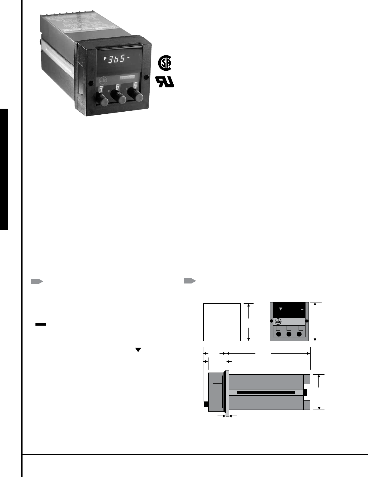
DIMENSIONS:
2.64
67.00
SQ.
Panel Cutout Dimensions
PANEL THICKNESS 1/16" TO 3/16"
.
with Memory
• EEPROM Memory
• Magnetic Latching Relay
• Delayed & Instantaneous
DPDT Contacts
• Switch Selectable SEC, MIN or HR Ranges
• Nine Ranges 0 to 9.99, 99.9 or 999
• High Accuracy & Noise Immunity
• Easy Plug-In Housing
PANEL MOUNTED DIGITAL TIMERS 365M Series
• High Intensity Blue Fluorescent Display
• Fully Gasketed and O-ring sealed to be dust tight
• Timeup or Timedown Display Operation
• 50 or 60 Hz Operation Self-Adjusting
E48329
Packaged in a 72mm2 DIN housing, the ATC 365 is a true plug-in timer
that can be replaced in seconds without disturbing the mounting housing or field wiring. Machine and process downtime is kept to a minimum.
The 365M is also fully gasketed and O-ring sealed to be dust tight.
WIDE RANGE: Each 365 timer covers the overall span of 0.01 SEC to
999 HR, in nine switch-selectable ranges of 9.99, 99.9, or 999 SEC,
Min, or HR.
EASY-TO-ADJUST PRESET: ATC’s unique three rotary switches for easy
setting and adjustment of the preset time is an industry standard. The
switches can be adjusted anytime, even during a timing cycle. The timer
is constantly scanning the preset setting and instantly re-computes the
time cycle if a preset change is detected. This is especially valuable in
the Timedown mode allowing you to shorten or abort the current time
cycle without the removal of power.
SELF-CALIBRATING: The microprocessor automatically calibrates the
timer for 50 or 60Hz power operation, there are no switches or jumpers
to set.
PROGRAMMABLE DISPLAY: An internal DIP switch can be set for Timeup
or Timedown and Stop display operation on the Arrangement 30 model.
The Arrangement 50 model can be set for Timeup or Timedown and go.
There is a horizontal timing bar “ ” which appears to the right of the
display and blinks once per second during timing and rapidly at timeout. At left, a timed out symbol “ ” blinks after time-out indicating when
the magnetic delayed relay is latched.
MAGNETIC LATCH RELAY: The 365 utilizes a unique magnetic latch
delayed relay which energizes, latches, at time-out. Once latched it will
not unlatch even with power removed or the unit is unplugged from the
housing. It will only unlatch when power is momentarily applied to the
Reset, terminal 16.
NON-VOLATILE MEMORY: An EEPROM memory chip to retain the time
value during a loss of power and continues timing when power is
restored. No battery is required.
OPERATION
Arrangement 30 & 50 Models
When power is applied to terminals 1 & 2 and 15 of the timer, the
instantaneous relay is energized and its contacts change state.
The timer starts timing, indicated by the display. The timing bar
“ ” blinks slowly and the digital display indicates elapse time
(Timeup & Stop) or time remaining (Timedown & Stop).
When the preset value is reached, the display stops, the timing bar
blinks rapidly, the triangular timed-out symbol “ ” blinks, and
the delayed relay latches and its contacts change state. The timer
remains in this timed-out condition until reset by applying power
to the Reset terminal 16 for at least 60 msec. At reset, both relays
revert back to their shelf state (without power).
Note 1: The delayed relay is a magnetic latch relay and once
latched it will not unlatch even if power is removed or the unit is
unplugged from the housing. It will only unlatch when power is
momentarily applied to the Reset terminal 16.
96
DIMENSIONS (INCHES/MILLIMETERS)
Panel Cutout Dimensions
365
2.64
67.00
SQ
1.50
38.10
1.10
27.95
5.31
134.87
3
6
2.83
72.00
SQ.
5
2.60
66.00
Page 2
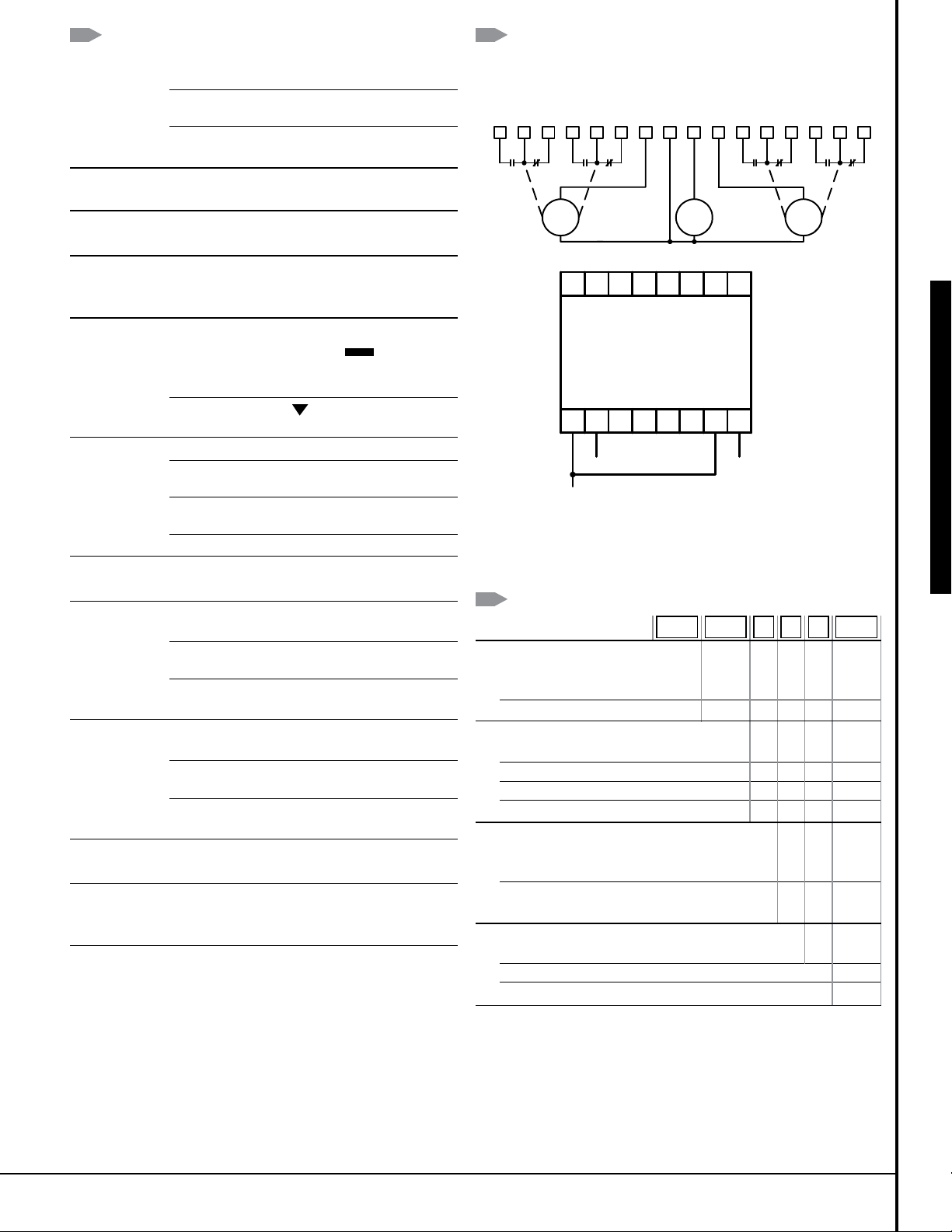
SPECIFICATIONS WIRING
MODELS Choice of two standard 120 VAC models
Each model available in 240 VAC or 24 VAC
365M300Q30PX Timeup & Stop or Timedown
& Stop, with display.
365M300Q50PX Timeup & Go or Timedown &
Go, with display.
RANGES Nine (9) Switch-Selectable ranges 0 - 9.99,
0 - 99.9, and 0 - 999 SEC, MIN, or HR
MEMORY 100,000 read/write cycles
RETENTION
RESET TIME Guaranteed not to reset <20 mSEC
Typical reset = 40 mSEC
Guaranteed to always reset >60 mSEC
DISPLAY Cycle Progress 3-digit high-intensity blue VF
display, 0.3 inch Timing Bar: “ ” display;
blinks once per second during timing, rapidly after
time-out.
Timed-Out Symbol: “ ”, blinks after time-out,
blinks when latch relay is latched
LOAD RELAYS Type DPDT, Form C
Contact Rating 7 Amps @ 120 VAC,
or 1/6HP @ 240 VAC
Operate Release 10 mSEC max.
Time
Life 10 million operations (no load)
TEMPERATURE 32 to 122°F (0 to 50°C)
RATING
POWER 120 VAC 50 or 60 Hz (10%, -20%)
REQUIREMENTS Running <100mA @120VAC
240 VAC 50 or 60 Hz (10%, -20%)
Running <50mA @ 240 VAC
24 VAC 50 or 60 Hz (10%, -20%)
Running <300mA @ 24 VAC
CLOCK INPUT 120 VAC 95 - 132 VAC,
(Terminal 15) 10 mA max. current @ 120V
240 VAC 90 - 264 VAC,
10 mA max. current @ 240V
24 VAC 19.2 - 26.4 VAC,
20 mA max. current @ 24V
TERMINALS 16 Screw (6-32) terminals with saddle clamps
accessible at rear
HOUSING 72mm2 DIN size, Plug-in design, fully gasketed
dust tight when panel mounted.
Panel mounting bracket included.
WEIGHT Net: 1 lb. 6 oz Shipping: 2 lbs.
MODEL NUMBER 365M P
RANGE
0 to 9.99, or 99.9 or 999 SEC, 300
MIN, or HR
Special 000
VOLTAGE & FREQUENCY
120 VAC 50-60 Hz Q
240 VAC, 50-60 Hz R
24 VAC, 50-60 Hz T
Special K
ARRANGEMENT
Selectable Timeup & Stop or Timedown & 30
Stop with Display, Standard
Selectable Timeup & Stop or Timedown & 50
Go with Display, Standard
FEATURES
Basic plug-in unit P
Standard unit X
Special K
Accessories:
Surface Mounting Bracket Kit 353-260-37-00
Retrofit Kit 305-265-61-70
Supply
L1 to Power
8 6 7 9 14 10 1 2 16 15 3 4 5 13 11 12
I2 I2 I1 I1
Power
Supply
14 13 12 11 10 9 8 7
REAR OF HOUSING
WHEN
PANEL MOUNTED
365M ARRANGEMENT 30 OR 50
1 2 3 4 5 6 15 16
L2
L1
L1 to Reset
L2 (common)
Reset
L1 to clock
START
RESET
Delayed ContactsInstantaneous Contacts
D2 D2D1 D1
Clock
MODEL NUMBER
PANEL MOUNTED DIGITAL TIMERS 365M Series
97
 Loading...