

Page 1
E48329
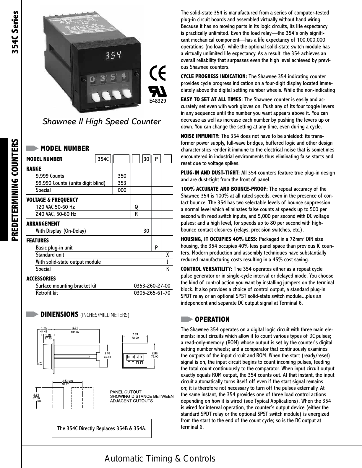
Shawnee II High Speed Counter
MODEL NUMBER
MODEL NUMBER 354C 30 P
RANGE
9,999 Counts 350
99,990 Counts (units digit blind) 353
Special 000
VOLTAGE & FREQUENCY
120 VAC 50-60 Hz Q
240 VAC, 50-60 Hz R
ARRANGEMENT
With Display (On-Delay) 30
PREDETERMINING COUNTERS 354C Series
FEATURES
Basic plug-in unit P
Standard unit X
With solid-state output module J
Special K
ACCESSORIES
Surface mounting bracket kit 0353-260-27-00
Retrofit kit 0305-265-61-70
The solid-state 354 is manufactured from a series of computer-tested
plug-in circuit boards and assembled virtually without hand wiring.
Because it has no moving parts in its logic circuits, its life expectancy
is practically unlimited. Even the load relay—the 354’s only signifi-
cant mechanical component—has a life expectancy of 100,000,000
operations (no load), while the optional solid-state switch module has
a virtually unlimited life expectancy. As a result, the 354 achieves an
overall reliability that surpasses even the high level achieved by previ-
ous Shawnee counters.
CYCLE PROGRESS INDICATION: The Shawnee 354 indicating counter
provides cycle progress indication on a four-digit display located imme-
diately above the digital setting number wheels. While the non-indicating
EASY TO SET AT ALL TIMES: The Shawnee counter is easily and ac-
curately set even with work gloves on. Push any of its four toggle levers
in any sequence until the number you want appears above it. You can
decrease as well as increase each number by pushing the levers up or
down. You can change the setting at any time, even during a cycle.
NOISE IMMUNITY: The 354 does not have to be shielded: its trans-
former power supply, full-wave bridges, buffered logic and other design
characteristics render it immune to the electrical noise that is sometimes
encountered in industrial environments thus eliminating false starts and
reset due to voltage spikes.
PLUG-IN AND DUST-TIGHT: All 354 counters feature true plug-in design
and are dust-tight from the front of panel.
100% ACCURATE AND BOUNCE-PROOF: The repeat accuracy of the
Shawnee 354 is 100% at all rated speeds, even in the presence of con-
tact bounce. The 354 has two selectable levels of bounce suppression:
a normal level which eliminates false counts at speeds up to 500 per
second with reed switch inputs, and 5,000 per second with DC voltage
pulses; and a high level, for speeds up to 80 per second with high-
bounce contact closures (relays, precision switches, etc.).
HOUSING, IT OCCUPIES 40% LESS: Packaged in a 72mm2 DIN size
housing, the 354 occupies 40% less panel space than previous IC coun-
ters. Modern production and assembly techniques have substantially
reduced manufacturing costs resulting in a 45% cost saving.
CONTROL VERSATILITY: The 354 operates either as a repeat cycle
pulse generator or in single-cycle interval or delayed mode. You choose
the kind of control action you want by installing jumpers on the terminal
block. It also provides a choice of control output, a standard plug-in
SPDT relay or an optional SPST solid-state switch module...plus an
independent and separate DC output signal at Terminal 6.
DIMENSIONS (INCHES/MILLIMETERS)
The 354C Directly Replaces 354B & 354A.
Automatic Timing & Controls
OPERATION
The Shawnee 354 operates on a digital logic circuit with three main ele-
ments: input circuits which allow it to count various types of DC pulses;
a read-only-memory (ROM) whose output is set by the counter’s digital
setting number wheels; and a comparator that continuously examines
the outputs of the input circuit and ROM. When the start (ready/reset)
signal is on, the input circuit begins to count incoming pulses, feeding
the total count continuously to the comparator. When input circuit output
exactly equals ROM output, the 354 counts out. At that instant, the input
circuit automatically turns itself off even if the start signal remains
on; it is therefore not necessary to turn off the pulses externally. At
the same instant, the 354 provides one of three load control actions
depending on how it is wired (see Typical Applications). When the 354
is wired for interval operation, the counter’s output device (either the
standard SPDT relay or the optional SPST switch module) is energized
from the start to the end of the count cycle; so is the DC output at
terminal 6.
Page 2

SPECIFICATIONS
CYCLE PROGRESS Indicating model only–digit, 0.3 inch, high
INDICATOR intensity, blue display
RANGE 1 to 9999 counts or 10 to 99,990, presettable
in 10 count increments.
PULSE INPUTS
Min. Open Resistance 1 megohm
Max. Closed Resistance 20K ohms.
Switch Requirements 10mA, 30V
With normal bounce immunity–for Reed
Switches (Terminal 9 jumpered to 13)
Max. Count Rate 500/SEC
Min. Closed Time 100 μSEC
Min. Open Time 1 mSEC
Max. Open Time for 0.3 mSEC
Any Single Bounce
bounce immunity–for Precision Switches
(Terminal 9 jumpered to 10 and 11)
Min. Closed Time 30 μSEC
Min. Open Time 6 mSEC
Max. Open Time for 2.5 mSEC
Any Single Bounce
VOLTAGE Positive Polarity On at 4.5V min.
INPUTS Off at 1.0V max
Negative Polarity On at 3.0V min.
Off at 1.0V max.
Max. Continuous Input 40V.
Ripple Voltage Must not go below min. req.
Input Impedance 5K ohms
Min. ON Time 60 μSEC
Min. OFF Time 100 μSEC
Count Rate 5K Hz max.
Rise and Fall Time Req. none.
DELAYED MODE Relay Operate Time 20 mSEC max.
(after coincidence)
Relay Release Mode 20 mSEC max.
INTERVAL MODE Relay Operate Time 15 mSEC max.
Relay Release Time 25 mSEC max.
(after coincidence)
AUTOMATIC Pulse On time (with relay)
RECYCLE MODE 80 mSEC, + 20 mSEC (may be shortened or
lengthened by installing a resistor or capacitor,
respectively, across Terminals 12 and 14; see
Application section for details)
Isolated Contact Input (Dry)
Count Rate and Bounce Immunity
Count Rate and Bounce Immunity with maximum
Max. Count Rate 80/ SEC
START
(READY/RESET) Positive Polarity ready at 4.5V MIN
SIGNAL reset at 1.0V max.
Max. Continuous Input 40V
Ripple Voltage must not go below MIN req.
Input Impedance 5K ohms
Ready-to-Count Time 0.5 mSEC max (after applica-
tion of voltage to Terminal 7)
Circuit Reset 1 mSEC max.
Ready-To-Dropout 20 mSEC max.
Start Switch Requirements (isolated contact)
Min. Open Resistance 1 megohm
Max. Closed Resistance 20K ohms
Min. Duration 50 μSEC
Start Signal
Max. Duration continuous
Start Signal
Reset when signal is removed after
count-out.
LOAD RELAY LIFE 100,000,000 operations
(no load)
Contact Rating 5 A at 120 VAC, 3 A at
28 VDC 1/20 HP at 120 VAC
SOLID-STATE Switches external DC voltage supply of positive
SWITCH polarity, 4 to 30V, 50 mA max.; factory-wired to
MODULE Terminals 3 and 5 (detailed description of operation
(OPTIONAL) in Installation Instruction)
DC OUTPUT Voltage ON– -24V+10%
(TERMINAL 6) OFF– -1V or less
Current with relay –5mA max.
without relay –40mA max.
Impedance on– 10 ohms max., off–10K ohms.
DC POWER Voltage 24V+10%
SUPPLY OUTPUT Current 40mA max
(TERMINAL 8)
POWER 120V 95 to 132V, 50/60 Hz
REQUIREMENTS inrush–0. 4A
running–0.04A.
240V 190 to 264V, 50/60 Hz
inrush–0.2A
running–0.02A.
TEMPERATURE 32° to 140°F (0 to 60°C)
RATING
MOUNTING Standard Hardware is provided to mount counter so
that it is dust-tight from front of panel.
Optional Surface mounting with front facing terminals.
NEMA 12 molded case (1 counter)
WEIGHT NET: 1 lb., 7 oz. SHIPPING: 2 lbs.
Voltage Requirements
Switch Rating 10mA, 30V
Latching Mode Operation (interval only)
PREDETERMINING COUNTERS 354C Series
When the 354 is wired for delayed control, the output device is
energized at the end of the cycle and remains on until the counter is
reset; so is the DC output.
When the 354 is wired as a repeat cycle pulse generator, the output
device and the DC signal are both off until the end of the count cycle,
Automatic Timing & Controls
at which time they are both on for about 80 mSEC From the instant that
the output pulse comes on, the 354 stops counting for 500 μSEC while
it resets; it automatically begins a new cycle and starts counting pulses
again immediately after reset. The duration of the pulse generated by the
354 can be easily lengthened or shortened by wiring a capacitor or resis-
tor across terminals 12 and 14 (see Typical Applications).
Page 3

WIRING
TERMINAL WIRING
SOLID STATE
OUTPUT MODULE
TYPICAL APPLICATIONS
The Shawnee 354 has a readily accessible 16-point terminal which
allows its use with a variety of start circuits and input pulses and to
program it for the desired load action. To wire the 354C so as to suit
a particular application is a relatively simple matter that is easily ac-
complished by selecting one of the examples in each of the follow-
ing four steps. Combine the four examples for your wiring diagram.
STEP 1 - START CIRCUITS
The 354 accommodates three types of star t signals. To wire the
counter properly to your start signal, first determine which of the
three types applies, then consult the appropriate wiring diagram.
NOTE: AC line connections are always made to Terminals 1 and 2.
A. ISOLATED CONTACT (sustained start signal) The external dry
start switch must be closed throughout the count cycle. The 354
is ready to count whenever the switch is closed; it resets when the
switch is opened.
PREDETERMINING COUNTERS 354C Series
ISOLATED CONTACT
START—
(EXTERNAL
START SWITCH
*Jumper for momentary
start in interval mode.)
STEP 2 - PROGRAMMING
The 354 can be used for delayed or interval control or as a repeat
cycle pulse generator. Here again, decide which mode you want, then
consult the appropriate wiring diagram. Note that the 354 counts on
the break of a contact or decrease of a voltage signal when an exter-
nal jumper is installed between Terminals 12 and 16, as shown in the
diagrams in this step. It can also be programmed to count on make
simply by leaving the jumper off.
A. DELAYED MODE. The SPDT relay provides one delayed closing and
one delayed opening circuit, and the 354 generates a DC signal at
Terminal 6 at the end of the cycle.
DELAYED MODE
B. INTERVAL MODE. The SPDT relay provides one interval open-
ing and one interval closing circuit, and the 354 provides a - 24VDC
signal at terminal 6 during cycle.
INTERVAL MODE
B. DC VOLTAGE (sustained start signal) The start voltage must be
on throughout the count cycle. The 354 is ready to count whenever
the voltage reaches +4.5 or -3V DC; it resets when the voltage drops
to +1 or -1V DC.
DC VOLTAGE START
(SUSTAINED START)
NEGATIVE DC VOLTAGE
(MOMENTARY* OR
SUSTAINED START)
Automatic Timing & Controls
C. NEGATIVE DC VOLTAGE (momentary* or sustained start signal.)
The start signal may be momentary or sustained. The 354 is ready
to count whenever the start voltage reaches -3V DC. It resets at the
end of the cycle, when the start voltage is momentary; or as soon
after count-out as the start voltage drops between -1 and 0V DC,
when the start signal is sustained.
D. REPEAT CYCLE PULSE GENERATOR. In this mode, the 354
generates an output of 80 ms (±20 ms) at the end of the count
cycle; the length of the output pulse can be adjusted as follows:
To shorten the pulse, install a fixed or variable resistor between
Terminals 12 and 14, sizing it according to this formula:
2.2t – 26.4
80-t
To lengthen the pulse, install a capacitor between Terminals 12
and 14 (if a polarized capacitor, install + to 12, - to 14) and size
it according to the formua:
T – 0.08
1.6
= R
= C
Where: t = time in ms (±25%)
R = resistance in megohms
Where: T = time in sec (±25%)
C = capacitance in microfarads.
Page 4

STEP 3 - PULSE INPUTS
The 354 can count from low or high-speed contacts or, by vir tue of
its built-in pulse shaper, from DC voltage pulses of positive or nega-
tive polarity. Choose the wiring diagram that suits your application.
LOW SPEED CONTACTS
A. LOW-SPEED CONTACTS. The 354 counts input pulses from preci-
sion switches, relays, limit switches, etc., at speeds up to 80/SEC.
B. HIGH-SPEED CONTACTS. Input pulses from low-bounce contacts,
reed switches, etc., can be counted at speeds up to 500/SEC. In
this circuit only, the 354 counts on the break of the pulse switch as
received; to count on make, install a jumper between Terminals 12
and 16; this is the reverse of the situation that applies to all other
354B circuits.
HIGH SPEED CONTACTS
A. DELAYED MODE. The load action in this mode is always the same
regardless of the kind of start circuit selected in Step 1; but the start
signal must remain on during the entire count cycle, as the counter
resets when the start signal is removed.
DELAY MODE
Before During End of
Start Timing Cycle
Start SW Reset to
LOAD A
LOAD B
-241/-27 VDC at Term 6
Before
Start
B. INTERVAL MODE WITH SUSTAINED START. In this mode also, the
counter resets when the start signal is removed.
INTERVAL MODE–SUSTAINED START
Before During End of
Start Timing Cycle
Start SW Reset to
LOAD A
LOAD B
-241/-27 VDC at Term 6
C. INTERVAL MODE WITH MOMENTARY START.
Before
Start
Because of the 354’s
electronic latch capability, it can provide interval control with a momentary
negative DC voltage start signal, in which event the 354 resets at the end
of cycle. But the counter will also operate with a sustained start signal, in
which case it resets when the star t signal goes off, as described above.
C. DC VOLTAGE PULSES. In this circuit, the 354 counts when the
voltage decreases from above +4.5V to below +1V, or from above –
3V to below –1V, with a jumper installed between Terminals 12 and
16 as shown in Section 2; to reverse the action, simply remove the
jumper.
COUNT DC VOLTAGE PULSES
STEP 4 -LOAD ACTION
The load action of the 354 depends on the choice of start circuit
and programming mode. Loads are always wired to the 354 in the
following manner:
If the 354 is equipped with the optional SPST solid-state switch
module, its contacts are always available at Terminals 3 and 5, and
its load action is the same as for Load B in the drawings right.
INTERVAL–MOMENTARY OR SUSTAINED START
Before During End of Cycle
Start Timing
Start SW
LOAD A
LOAD B
-241/-27 VDC at Term 6
D. REPEAT CYCLE PULSE GENERATOR. When this mode is selected, the
start signal must remain on continuously. The 354 generates an output
pulse at the end of each count cycle, then resets and repeats automati-
cally. At least 500 μs is required for resetting, between the last count of
one cycle and the first count of the next. Count pulses can be of unequal
length – long and short as shown in the diagram – provided that they
meet the minimum requirements listed in the SPECIFICATIONS.
REPEAT CYCLE GENERATOR
DURING CYCLE
Before
Start C C C C Reset
Start SW
LOAD A
LOAD B
-24/-27 VDC
At Term 6
PULSE SW
C=COUNT CYCLE=DIAL SETTING
=TIMED PULSE OUTPUT
BLACK– CIRCUIT CLOSED
GRAY– CIRCUIT OPEN
PREDETERMINING COUNTERS 354C Series
Powered by TCPDF (www.tcpdf.org)Powered by TCPDF (www.tcpdf.org)Powered by TCPDF (www.tcpdf.org)
Powered by TCPDF (www.tcpdf.org)Powered by TCPDF (www.tcpdf.org)
Automatic Timing & Controls
 Loading...