

Page 1

User Manual:
Active: SCM25A Pro
Passive:
. SCM50ASL . SCM100ASL . SCM110ASL . SCM150ASL
. SCM50SL . SCM100SL . SCM110SL . SCM150SL
MULTICHANNEL
®
SCM25A Pro
SCM50
SCM100
SCM110
ACOUSTIC ENGINEERS
SCM150
Page 2

SafetyWarnings
1. Read instructions – all the safety and operating instructions should be read
before the appliance is operated.
2. Retain these instructions – the safety and operating instructions should be
retained for future reference.
3. Heed warnings – all warnings on the appliance and in the operating
instructions should be adhered to.
4. Follow instructions – all operating and other instructions should be
followed.
5. Water and moisture - the appliance should not be exposed to dripping or
splashing and no objects such as vases, should be placed on the appliance.
6. Ventilation - a minimum 0f 80mm is required at the rear of the appliance
to ensure sufficient ventilation.The ventilation should not be impeded by
covering the appliance with items such as table-cloths,curtains etc. Further,
the appliance should not be built into an installation, such as a bookcase or
cabinet, that may impede the flow or air around the appliance.
7. Heat – the appliance should be situated away from heat sources such as
radiators, stoves or other appliances that produce heat.
8. Power sources -The appliance is of Class1 construction and shall be
connected to a MAINS socket outlet with a protective earthing connection.
9. Power cord protection – power supply cords should be routed so that they
are not likely to be walked on or pinched by items placed upon or against
them, paying particular attention to cords at plugs, convenience
receptacles and the point where they exit the appliance.
10. Cleaning – the appliance should be cleaned only as recommended by the
manufacturer.
11. Unattended periods – the power cord of the appliance should be
unplugged from the outlet when left unused for a long period of time.
12. Object entry – care should be taken so that objects do not fall into the
appliance.
13. Damage requiring service – the appliance should be serviced by qualified
service personnel when:
i. the power supply cord or the plug has been damaged
ii. objects have fallen or liquid has been spilled into the appliance
iii. the appliance has been exposed to rain or other serious liquid exposure
iv. the appliance does not appear to operate normally or exhibits a marked
change in performance
v. the appliance has been dropped or the cabinet damaged
14. Servicing – the user should not attempt to service the appliance beyond
those measures described in the operating instructions.All other servicing
should be referred to qualified service personnel.
15. Grounding or polarisation – precautions should be taken so that grounding
or polarisation means for the appliance are not defeated.
16. The Mains disconnection switch is located on the rear panel.Pressing the
switch downwards will turn the unit on.The unit can be turned off by upward
pressure on the switch. Please allow enough room around the unit to ensure
the switch is readily operable when the unit is in use.
SCM 50/100/ 15025/ 110/
1
Page 3

SCM 50/100/ 15025/ 110/
SCM 50/100/ 15025/ 110/
Welcome. In selecting ATC you have chosen an
example of the finest audio engineering
available. ATC was founded on a principle of
engineering excellence, and that principle still
defines our products today. Given the right
opportunities, ATC products will deliver
exceptional audio performance, but the
opportunities will only arise from careful and
thoughtful installation and use. Please read the
following manual fully. It will help you
understand the product and to realise its full
potential. We are happy to answer questions
and offer advice on any issues that arise
through installation or use of ATC products.
Contact details can be found at the back of this
manual.
Introduction
ATC was founded in London in 1974 by Australian emigre Bill Woodman, who still
heads the company today. An enthusiastic pianist and engineer he was naturally
drawn to loudspeaker design and after a period working at Goodmans, where many
of the names that went on to found British loudspeaker companies began their
careers, he struck out on his own.The premise on whichATC began is a simple one,
and one that in many respects is still true today: hi-fi loudspeakers tend to be
detailed and accurate but of limited dynamic range, while professional monitor
speakers tend to express the opposite character. ATC products were designed from
the outset to offer the best of both. It’s an easy concept to describe, but surprisingly
difficult to engineer.
Contents
Page 2 Introduction
Page 3
Page 4 ASL monitors
Page 5 SL monitors
Page 7
Page 8
Section 1 Description
Section 2 Unpacking and Handling
Section 3 Monitor Placement
Section 4 Listening
Section 5 Signal Cable Options
Section 6 Operation
Section Connection7
Section Connection8
Section 9 Amplification
Specifications
Section 10
Section 11
Care and Maintenance
Warranty and Contact
The difficulty inherent in designing such loudspeakers is one of scale. Hi-fi levels of
accuracy and detail call for lightweight moving parts and delicate engineering.
Professional monitor levels of performance however demand far more robust
components engineered to survive the rigours of high level use for extended
periods.The only way to combine the two is through precision engineering of a class
and scale more often associated with aerospace or motorsport.But the results are
worth the effort and the cost. ATC loudspeakers, with their unique in-house
designed drivers, combine the best of hi-fi and professional to devastating effect.
ATC has become synonymous with active systems. Choosing to offer active
loudspeakers (where the passive crossover network is replaced by active filters and
multiple power amplifiers) is simply a result of the uncompromising attitude to
loudspeaker design.While passive systems still have their place, andATC engineering
skills can still bring remarkable results from them, “active” is a fundamentally better
solution to the problems posed by accurate, high level music reproduction.The ATC
instinct is always for the better solution. Not cheaper,not quicker, but better.
It was the development of active loudspeakers that first brought ATC into
electronics design and engineering. Active speakers demand multiple power
amplifiers so ATC from the mid 1980s became not just a loudspeaker manufacturing
company but an electronics manufacturer too.The further step from electronics for
active speakers to a range of stand-alone amplifier products was natural and now
means that ATC engineering is available from the recording desk or CD player
output to the ears.
From modest beginnings ATC has grown to become one of the very few
manufacturers successful across both domestic and professional audio. By selecting
ATC you join a group of music lovers, professional audio engineers, studios and
musicians across the World that understand and value the engineering that goes into
an ATC product - and the sound that comes out.
2
Page 4
SCM 50/100/ 15025/ 110/
1. Description
The SCM25/50/100/110 and 150 are a range of three way
loudspeakers. All of the range, excluding the SCM25 are
available as passive or active units, the SCM25 is only
available as an active unit. Passive units have an SL suffix
and active units an ASL suffix. Passive monitors are
equipped with a “tri-wire” connection panel to enable
separate amplification of the bass, mid and high frequency
drivers. Active units have a built in three way Amplifier
with frequency, gain and phase correction which has been
individually optimised at the ATC manufacturing facility.
Adjustment of input sensitivity and bass boost are available
to the user via controls on the rear panel of the unit.
2. Unpacking and Handling
The SCM25, 50, 100, 110 and 150 are large heavy items and
should be handled with care. Always employ a second
person to assist in moving them. Unpacking is best carried
out on the floor, with adequate open space around the
carton, preferably close to their final position.
• Open the carton and remove all loose items.
• Remove the upper Sratocell foam cap.
• Remove the polythene or cloth bag, leaving
the baffle protector in place.
• Carefully lift the loudspeaker out from the
lower Sratocell foam cap using the handles
and the port opening as lifting points.
• The speaker can now be positioned in the
listening/control room
• Remove the baffle protector.
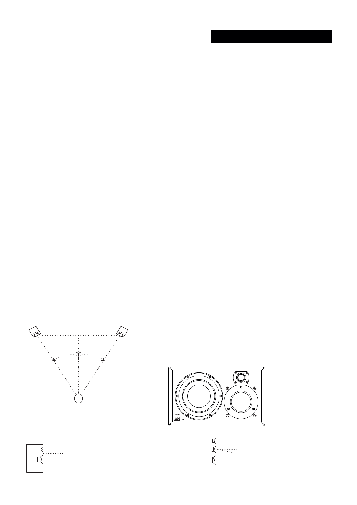
Loudspeaker Positioning - Stereo
distance z
30°
distance x
30°
Fig. 1
distance y
3. Monitor Placement
The subjective performance of any monitor loudspeaker will be influenced by the
acoustic character of the room in which it is used, and its position within the room.
Most often monitors are installed in rooms which are comfortable to sit and talk in.
A mixture of carpets, curtains and soft furnishings will help ensure that middle and high
frequencies are reasonably well controlled. There may however be low frequency
problems; either too much or too little bass. To minimise low frequency problems
the monitors should be kept away from corners or walls. Start with them positioned
on appropriate stands 1 metre from the side walls and 2 metres from the back wall
In professional installations, try to avoid placing speakers on the console/desk meter
bridge. Typically, this compromises the balance of the loudspeaker especially in the
lower mid range. If the balance is bass light, the monitors can be moved towards the
back walls. for fine tuning rather than to compensate forUse the Bass Boost control
innapropriate positioning. For stereo listening, loudspeakers should be positioned
so they form an equilateral triangle with the listening position (See Fig.1).
Loudspeaker stand height should be chosen to position the loudspeaker
acoustic axis at, or close to ear level (See Fig.2). All rooms vary and it is a good idea
to experiment with both the listening and speaker position until a good compromise
is reached. For professional installations the requirements are often very specific.
Please consult with an experienced professional acoustician if necessary.
Monitors with an asymmetric (offset) driver array should be positioned such that the
midrange driver and tweeter are inboard. If the monitors are to be placed in any form
of cabinet, adequate side and top clearance for cooling airflow must be provided.
Alternatively, the Amplifiers should be removed and installed remotely. All ATC 3-way
loudspeakers are designed with the mid-range dome as the reference acoustic axis.
With this in mind, the loudspeakers should be positioned with the mid-range dome
at, or slightly below ear level (See Fig.2).
4.Listening
The ear and brain tend to interpret distorted sound as loudness and thus
underestimate the actual level of undistorted sound.The SCM50, 100 and 150, like
all ATC monitors, demonstrate very much lower levels of distortion than
conventional systems of a similar size and it is therefore advisable to begin listening
at an artificially low level and carefully increase the volume.It is also possible for the
SCM50, 100 and 150 to produce sufficient sound pressure levels for your ears
themselves to become a source of distortion and make the sound appear harsh. Any
audible distortion indicates that either the system or your ears are being overloaded
and that the volume level should be reduced.
Fig. 2
distance x = distance y = distance z
2-way systems
acoustic axis: mid point between
bass/mid and tweeter
Reference acoustic axis
Position at ear level or up
to 5 degrees above ear level
3-way systems
acoustic axis: 5 belowº
mid-range driver
3
Page 5
SCM 50/100/ 15025/ 110/
ASL monitors
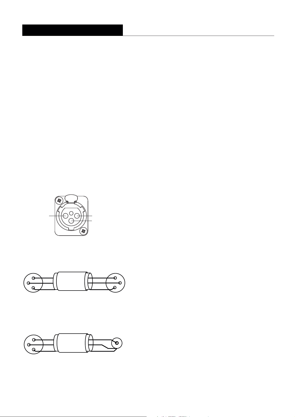
5. Signal Cable Options
Balanced cable configuration is the preferred option,
however unbalanced connection is possible. Diagrams 2 and
3 illustrate the signal cable connections required for
each option. Balanced (XLR to XLR) connection offers
lower noise and better immunity to “hum” pick-up.
Unbalanced (XLR to Phono or Two pole Jack)
connection carries risk of hum caused by multiple
signal earths. Hum problems resulting from unbalanced
connection may be reduced by making ONE of the
following modifications to the signal cable
connections: If the driving preamplifier (or desk) is
“double insulated” (i.e. has no mains earth),
disconnect the signal cable screen at the RCA Phono
plug end. Alternatively, disconnect the signal cable
screen at the XLR end.This second option will make
the source the reference signal earth.
Diagram 1 - input connection pins
PUSH
Pin 2, Signal (hot)
21
3
Pin 1, Screen
Pin 3, Signal (return)
6.Operation
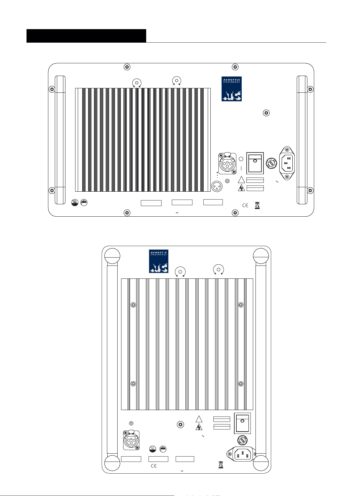
Diagram 4 illustrate the connection and controland 5 panels for the Amplifiers
used in the active monitors. Each feature is described below.
5.1 Mains Inlet:
territory) should be connected here. Ensure that the mains voltage specified on
the panel corresponds with the local supply voltage.
5.2 Power Switch:
on the switch will illuminate.
5.3 Fuseholder:
operated the fuse should be inspected. Lift out the fuseholder cover using a
small flat-blade screwdriver th efuse and inspect it for damage. Ifremove
required a replacement fuse should be fitted, . It should be stressed however that
fuses most most electrical fault. If this is theoften fail only because of a serious
case then simply replacing the in another fuse failure. Thefuse will only result
monitor should be returned to ATC if a second fuse fails.
5.4
Input Socket:The audio signal cable should be connected here. Balanced or
or unbalanced cables may be used (See Section 3).
5.5
Bass Boost:
flat blade screwdriver to access the control. Adds more warmth and energy to
the lower frequencies in music, at the expense of accurate transient
reproduction. Note:
may leave a pair of monitors unmatched.
The supplied mains power lead (appropriate to the local
Switches on the monitor When. switched on the indicator
Should a monitor fail to switch on when the power switch is
Provides up to 6dB of gain in the region of 40Hz. Use a small
Adjusting the bass boost without the ability to recalibrate
Diagram 2 - balanced cable
3 Pin Male XLR
Connector
2
3
1
To Monitor Input
Two Core Screened Cable
Diagram 3 - unbalanced cable
3PinMaleXLR
Connector
2
3
1
To Monitor Input
Two Core Screened Cable
3 Pin Female XLR
Connector
Hot
Return
Screen
To Source Output
Phono (RCA)
Hot
Return
Screen
To Source Output
2
1
Connector
LevelTrim: Provides access to an internal control that enables
5.6
adjustment of input sensitivity. Use a small flat blade screwdriver to access the
control. As supplied, monitors are calibrated to an input sensitivity of 1V.
Note:
Adjusting the sensitivity without the ability to recalibrate will leave a pair
of monitors unmatched.
3
Due to the nature of the electronics in ATC active loudspeakers it is quite normal
for a sound to be heard from the speaker when the power is applied or
disconnected. The noise heard will not damage the speaker and is quite normal.
Although ATC uses the highest-grade components, a different noise may be heard
from each speaker due to slight tolarance variations in the amplifier components.
7.Connection
Two cable connections are required for each monitor: one for mains power and one
for the audio signal. The mains cable is specifically supplied to comply with local
statutory safety approvals and alternatives should not be substituted. If you intend to
use your monitors in an alternative territory please contact ATC for advice.The mains
connection must always be earthed.
The signal cable and plug (not necessarily supplied) should be of a good quality and
XLR terminated. Poor cable and plug quality will compromise the performance of
your monitors.The signal input pin configuration is illustrated in Diagram 1.
4
Page 6
SCM 50/100/ 15025/ 110/
SL Monitors
8.Connection
The monitors are equipped with a “tri-wire” connection
panel to enable separate amplification of the bass driver
mid driver and tweeter. Remove the linking bars between
the three pairs of terminals if you wish to take advantage
of the tri-wire facility.
The terminals can accomadate either stripped cable ends
or 4mm plugs: Always use good quality speaker cable with
a 2.5mm minimum cross sectional area per conductor
(79 strand). Cable of smaller cross sectional area or fewer
strands is unsuitable. For cable runs longer than 10m use
a significantly heavier gauge cable. Consult your dealer or
consultant for specific cable recommendations.
Ensure that the positive and negative terminals on each
connection panel are connected back to the corresponding
positive and negative terminals on the amplifier
9.Amplification
The choice of partnering amplifier for the monitors will
have significant influence on the performance of the system.
Consider the following when selecting the amplifier:
• With any passive loudspeaker there is a trade-off between
low frequency extension and sensitivity. The monitors
extended low frequency response means that its sensitivity
is relatively low. It is advisable therefore to select an
amplifier of relatively high power capabilities. Use of an
under specified amplifier will result in the system sounding
distorted at high levels and may risk damage. Valve or solid
state amplifiers with high output impedance should be
auditioned carefully to establish that their characteristic
reduced damping at low frequencies is acceptable.
• Thanks in part to Super Linear technology and underhung
voice coil construction, the monitors not only demonstrate
extremely low distortion at all levels but also a greatly
enhanced effective dynamic range. This exceptional
distortion performance, also combined with very wide
dispersion, will ruthlessly reveal deficiencies in ancillary
equipment. It is advisable therefore to audition the monitors
with your proposed amplifier and ancillary system.
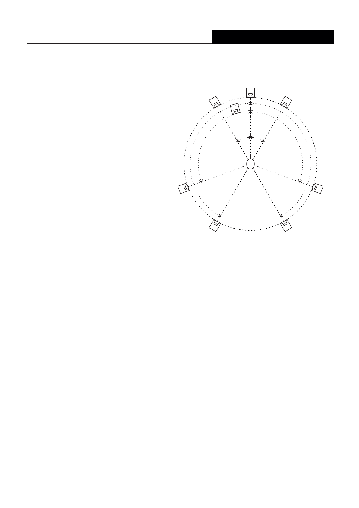
Loudspeaker Positioning - 5.1 & 7.1 Surround
centre
right
distance RS
right
110°
150°
right
rear
side
left
150°
left
110°
distance LS
left
rear
sub
distance LR
distance C
distance L
30°
30°
distance R
distance RR
• All loudspeakers should be equi-distant from the listening position:
distance L = distance C = distance R = distance LS = distance LR = distance RR
• For 5.1 systems, position the ‘surround’ speakers between 110 and 150 degrees
• If ideal positioning is not possible, position loudspeakers as close as possible
to ideal
• Try to avoid placing the subwoofer on the mid-point between two walls
• For more details on setting up surround playback or monitoring systems
please contact you dealer or ATC direct.
side
5
Page 7
SCM 50/100/ 15025/ 110/
Diagram 4 - connection and control panelSCM25A Pro
can only be safely used lower than 2,000 metres altitude
2000m
can only be safely used in non-tropical weather
bass boost
+3dB
Input sensitivity
0dB (ref.)
2v/8.2dBu
model
Acoustic Transducer Co. Is a trading name and
(full output)
1v/2.2dBu (ref.)
serial no.
Is the registered Trade Mark of LoudspeakerTechnology Ltd.
Designed and manufactured by
Acoustic Transducer Company
R
Tri - AmpPack
High Performance
Active Loudspeaker
Laite on liitettävä suojakoskettimilla varustettuun pistorasiaan
balanced input
PUSH
1:
2:
fault
3:
2
1
3
voltage
Apparatet må tilkoples jordet stikkontakt
Apparaten skall anslutas till jordat uttag
power
WARNING
THIS EQUIPMENT
!
MUSTBE EARTHED
CAUTION
RISK OF ELECTRIC SHOCK
DO NOTOPEN
CHECKVOLTAGE BEFORE USE
NO USER SERVICEABLE PARTS INSIDE
Gloucestershire GL6 8HR
England
115/220 - 230V
fuse:
115V :T6.3A H/250V
220 - 230V :T3.15A H/250V
MAINS INPUT
50/60 Hz
POWER
CONSUMPTION
425WATTS MAX.
RETURNTO
MANUFACTURER
FOR DISPOSAL
Diagram - connection and control panel5 SCM50/100/110/150
R
+6dB
Tri - AmpPack
High Performance
Active Loudspeaker
bass boost
0dB (ref.)
2v/8.2dBu
Input sensitivity
(full output)
1v/2.2dBu (ref.)
220 - 230V :T3.15A H/250V
RETURNTO
MANUFACTURER
FOR DISPOSAL
WARNING
THIS EQUIPMENT
MUSTBE EARTHED
CAUTION
RISK OF ELECTRIC SHOCK
DO NOTOPEN
100/115/220 - 230V
fuse:
100V :T6.3A H/250V
115V :T5A H/250V
Designed and manufactured by
fault
Acoustic Transducer Company
Gloucestershire GL6 8HR
balanced input
PUSH
21
3
model
6
England
Apparaten skall anslutas till jordat uttag
Apparatet må tilkoples jordet stikkontakt
Laite on liitettävä suojakoskettimilla varustettuun pistorasiaan
can only be safely used lower than 2,000 metres altitude
2000m
can only be safely used in non-tropical weather
serial no.
NO USER SERVICEABLE PARTS INSIDE
CHECKVOLTAGE BEFORE USE
Acoustic Transducer Co. Isa trading name and
!
MAINS INPUT
50/60 Hz
POWER
CONSUMPTION
625WATTS MAX.
voltage
Is the registered Trade Markof Loudspeaker Technology Ltd.
Page 8

Specifications
ASL Monitors
Drivers:
HF
MF
LF
Amplitude Linearity ±2dB
Cut-off Frequencies
(-6dB free standing)
Matched Response
Dispersion:
Max Continuous SPL
Crossover Frequencies
Input Connector
Input Sensitivity
Sensitivity Trim
Input Impedance
Amplifier Output:
Overload Protection
Bass Boost
Cabinet Dimensions (HxWxD)
OverallWeight
Power Requirements:
Stands/Brackets
Cabinet Finishes
Horizontal
Vertical
LF continous
MF continous
HF continous
Voltage
Frequency
SCM25A Pro
25mm (1")
75mm (3")
164mm (7")
7 Hz–1 kHz47
47Hz & 22kHz
±0.5dB
±80° Coherent
±10° Coherent
1 dB SPL @ 1 metre09
150 Watts
60 Watts
25 Watts
0 to +3dB @ 40Hz
264 x 430 x 408mm
30.0kg (66lbs)
115/220 - 230V
50/60Hz
All products: Standard real wood veneers are available in Black Ash, Mahogany, Cherry and Natural Oak.
Other veneers and finishes can be supplied to special order.
SCM 50/100/ 15025/ 110/
SCM50ASL
25mm (1")
75mm (3")
234mm (9")
70Hz – 12kHz
38Hz & 20kHz
±0.5dB
±80° Coherent ±80° Coherent
±10° Coherent
112dB SPL @ 1 metre
380Hz and 3.5kHz, 4th order, critically damped with phase compensation
1V rms (0dBV/1.1dBu) balanced (referenced to full output)
200 Watts
100 Watts
50 Watts
Active omentary Gain Reduction on all .peak m channels, r.m.s. power limiter on h.f. channels
717 x 304 x 480mm
48.9kg (107.5lb)
Floor stands included with Hi-Fi products only
SCM100ASL
25mm (1")
75mm (3")
314mm (12")
65Hz - 12kHz
32Hz & 20kHz 25Hz & 20kHz
±0.5dB ±0.5dB ±0.5dB
±10° Coherent
115dB SPL @ 1 metre
Female XLR
0 to -6dB (Pro Versions only)
10k Ohms per leg
200 Watts
100 Watts
50 Watts
834 x 400 x 585mm
64.8kg (142.5lb)
SCM110ASL
25mm (1")
75mm (3")
314mm (12")
65Hz - 12kHz
32Hz & 20kHz
±80° Coherent
±10° Coherent
115dB SPL @ 1 metre
200 Watts
100 Watts
50 Watts
0 to +6dB @ 40Hz
834 x 400 x 585mm
64.8kg (142.5lb)
Internally setInternally set
100, 115, 230V220 -
50/60Hz
SCM150ASL
25mm (1")
75mm (3")
375mm (15")
60Hz - 12kHz
±80° Coherent
±10° Coherent
117dB SPL @ 1 metre
200 Watts
100 Watts
50 Watts
884 x 498 x 568mm
75.0kg (165.3lb)
SL Monitors
Drivers:
Amplitude Linearity ±2dB
Cut-off Frequencies
(-6dB free standing)
Matched Response
Dispersion:
Max Continuous SPL
Crossover Frequencies
Input Connector
Sensitivity @ 1 Watt/metre
Nominal Impedance
Recommended Power Amplifier:
Cabinet Dimensions (HxWxD)
OverallWeight
Stands/Brackets
Cabinet Finishes
Specifications comply with the following standards: Australian Standard Specification No 1127 "Sound System Loudspeakers" Part 5, IEFE Specification Standard No 219-1975
E. & O.E. The policy of ATC is that of continuous design and development. ATC reserves the right to alter products and specifications without prior notice.
Acoustic Transducer Co. is a trading name and ATC is the registered trade mark of LoudspeakerTechnology Ltd.
HF
MF
LF
Horizontal
Vertical
SCM50SL
25mm (1")
75mm (3")
234mm (9")
70Hz – 12kHz
38Hz & 20kHz
±0.5dB
±80° Coherent ±80° Coherent
±10° Coherent
112dB SPL @ 1 metre
380Hz and 3.5kHz, 4th order, critically damped with phase compensation
85dB
717 x 304 x 480mm
41.1 90.5kg ( lb)
All products: Standard real wood veneers are available in Black Ash, Mahogany, Cherry and Natural Oak.
Other veneers and finishes can be supplied to special order.
SCM100SL
25mm (1")
75mm (3")
314mm (12")
65Hz - 12kHz
32Hz & 20kHz 25Hz & 20kHz
±0.5dB ±0.5dB ±0.5dB
±10° Coherent
115dB SPL @ 1 metre
Binding Posts/4mm Sockets (Tri-Wire capable)
8 ohms
100 - 1500 Watts
834 x 400 x 585mm
57.0kg (126.5lb)
Floor stands included with Hi-Fi products only
SCM110SL
25mm (1")
75mm (3")
314mm (12")
65Hz - 12kHz
32Hz & 20kHz
±80° Coherent
±10° Coherent
115dB SPL @ 1 metre
834 x 400 x 585mm
57.0kg (126.5lb)
SCM150SL
25mm (1")
75mm (3")
374mm (15")
60Hz - 12kHz
±80° Coherent
±10° Coherent
117dB SPL @ 1 metre
90dB88dB88dB
884 x 498 x 568mm
67.2kg (148.1lb)
7
Page 9

SCM 50/100/ 15025/ 110/
10. Care and Maintenance
High technology material finishes are used in this product.The surfaces are durable
and with a little care can be kept as good as new even under conditions of heavy
use. Normally a dry duster will be all that is required to keep the finishes clean.
Heavy soiling can be cleaned using a cloth slightly moistened with a non-abrasive
household cleaner.
There are no components within the speaker that can be considered expendable,
or that would benefit from regular maintenance. There is no requirement for any
kind of routine service work and there is no schedule for preventative maintenance.
There are no user replaceable parts within the speaker and in the unfortunate event
of any malfunction, repair should be referred to either the supplying dealer or
consultant, the relevant importer, or ATC. ATC has every confidence in the quality
of each product that it manufactures.
11. Warranty and Contact
All ATC products are guaranteed against any defect in materials or workmanship for
a period of two years from the date of purchase.Within this period we will supply
replacement parts free of charge provided that the failure was not caused by misuse,
accident or negligence.
Purchasers who complete and return the Warranty Card will have their
warranty period extended up to a period of six years from the date of
purchase.This guarantee does not limit statutory rights.
ATC can be contacted at:
Loudspeaker Technology Ltd, Gypsy Lane, Aston
Down, Stroud, Gloucestershire GL6 8HR, UK.
Telephone: 01285 760561
Fax: 01285 760683
Email: [email protected]
Website: www.atc.gb.net
8
Page 10

®
ACOUSTIC ENGINEERS
Loudspeaker Technology Ltd, Gypsy Lane, Aston Down, Stroud, Gloucestershire GL6 8HR United Kingdom
Telephone 01285 760561 Fax 01285 760683
Email: [email protected] Website:www.atc.gb.net
 Loading...