

Page 1
AT 8000 Series fast installation guide
Installation steps:
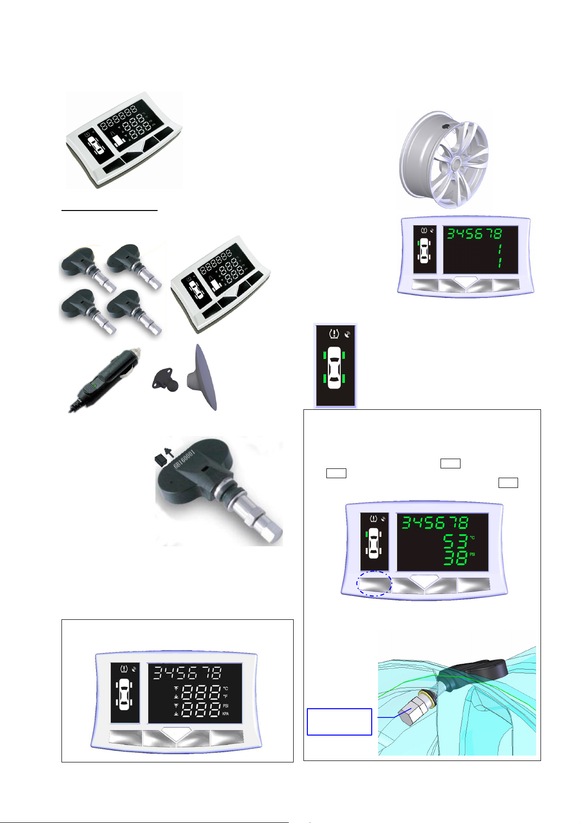
Step 1: Check components
Welcome to AT 8000 Series
Tire Pressure Monitoring
System (TPMS). This Fast
installation Guide is intended
to give you a fast overview of
the key steps required to
install your AT 8000 Serial
TPMS. For more detailed
information, please refer to the
8000 Serial TPMS Installation
Guide.
Step 5: Installing one sensor into wheel
Please get help from professional tire shops if necessary.
1. Remove the wheel
from vehicle,
Deflate, and
separate rim and
tire.
2. Fix sensor on rim.
3. Assemble rim and
tire, inflate to
typical pressures.
4. Balance wheel and
install to vehicle.
5. Use receiver to
search ID of this
wheel again, and
assign this ID to
the position
respect to this tire
installation. Make
sure that the
sensor inside tire
was keeping work
well.
Steps 6: Continue to install all other sensors with
the same procedure.
Install all tires to the right positions of vehicle. Using
receiver to search and assign all IDs to correct
position respect to tire installation.
Steps 7: Setup pressure and temperature
thresholds according to tire type.
Step 2: Check identification number
Each sensor should be
assigned a unique
identification number
(ID), which was marked
on the top of sensor.
Step 3: Enable and Test
sensors before installing
To enable a sensor, it is
only needed to pull out
the jumper attached on
sensor. After successfully
enabled, sensor will start
to measure environment air pressure and temperature and send them to
receiver.
Step 4: Set up the receiver
Plug the attached power cord into Receiver and insert the other terminal
to the cigarette electrical socket of vehicle. You can adjust parameters
of receiver according to your requirement.
Only the first two and last four digitals of ID will show on panel
of receiver, for example, if ID is 34125678, only345678 will be
shown.
Do not mix up each tire’s ID, or the detected tire parameter
may not be correct!
It is easy to identify each tier’s ID by changing its pressure
(slightly deflate) and monitor the receiver for checking this
pressure variation and tire position.
Check all recorded tire IDs by press Key 1. Each single press on
Key 1 can call one tire parameters out, including temperature,
pressure, and identification code. Continually press on Key 1 can
read tire parameters one by one.
Key1 Key2 Key3 Key4
Typical torque of new valve nut is 3~5 N-m(30~50 kgf-cm).
In order to guarantee sealing, be sure that the rubber rings are
properly positioned between rim and valve.
Valve nut
Page 2
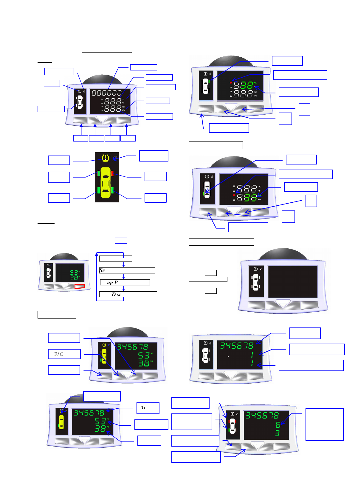
Receiver Setting
Key 1 Key 2 Key 4
N
umeric row 1
N
umeric row 2
N
umeric row 3
Status displayer
Temperature unit
Pressure unit
Alarm
Receive Status
Key 3
Alarm
Tire 1
Tire 4
RF Symbol
Tire 2
Tire 3
℉/℃
Select
tire
Temperature
Pressure
Select tuning item
+
-
Setting tire
High/Low limit indication
Temperature limit
PSI/KPA
Setting tire
High/Low limit indication
Pressure limit
-
+
Select
tuning item
2
1
Panel
Modes
In order to integrate friendly operation interface and powerful parameter
adjusting function, AT8000 contains four major operation modes, and it
is easy to switch between them by press Key 4 over 0.5 second:
Working mode
Key functions:
Display
Working mode
Setup Temperature limits
Setup Pressure limits
Tire ID search and assign
Graphic display
↓↓↓↓
↓↓↓↓
↓↓↓↓
Tire ID
Setup Temperature limits
Setup Pressure limits
Tire ID search and assign
Step 1:
ID search mode by:
1. Press Key 4 into
Tire ID search and assign
mode.
2. Press Key 1
confirm to search.
Switch into
Step 2:
Step 3:
ID assigned Tire
Selected Tire for
assigning
Press to assign ID
Select Tire to assign ID
Waiting for ID search
Assign searched ID to exact position
2
1
2
1
Selected ID
One ID had been searched
First received ID was selected
Select ID from
ID buffer.
The third of six
ID.
Page 3

FCC Notice:
Notice : The changes or modifications not expressly approved by the party responsible
for compliance could void the user’s aut hority to operate the equipment.
IMPORTANT NOTE: To comply with the FCC RF exposure compliance requirements, no change
to the antenna or the device is permitted. Any change to the antenna or the
device could result in the device exceeding the RF exposure requirements
and void user’s authority to operate the device.
This device complies with Part 15 of the FCC Rules. Operation is subject to the following two
conditions: (1) this device may not cause harmful interference, and (2) this device must accept any
interference received, including interference that may cause undesired operation.
910805
2
 Loading...