

Page 1
Installation Guide
The panels, flashings and trim shown in this guide, illustrated
over solid and plumb substrate, assume that the structure has
been designed and prepared in accordance with local building
codes.
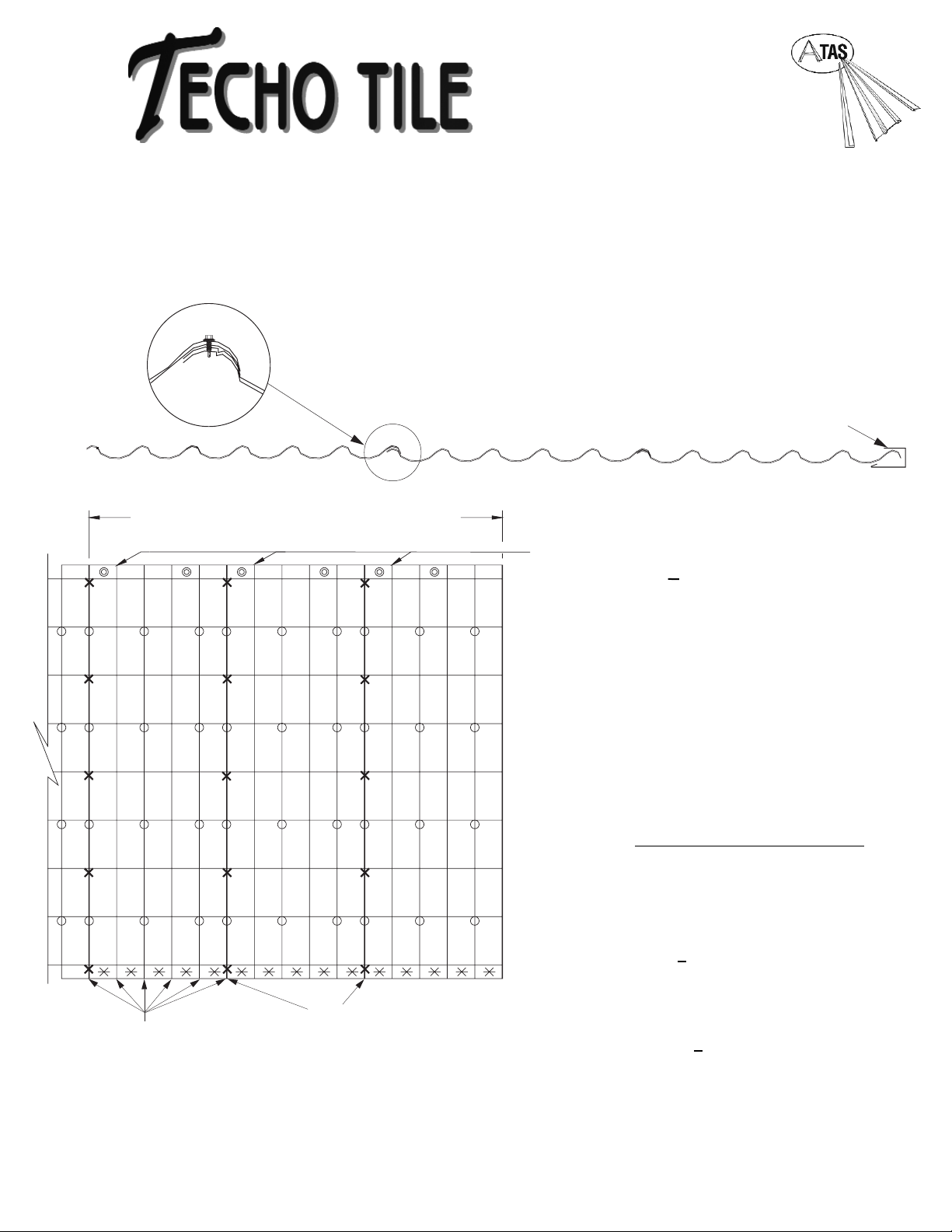
X - Stitch Screw
SWR8XX
Approximately 15/sq.
X - Anchor Screw
SWR9XX
Approximately 1 for every
8” of eave.
O - Screws
SWR6?? (for metal)
SWR7?? (for wood)
Approximately 38/sq.
O- RSS211 (for wood)
RSS210 (for metal)
Approximately 8/sq.
PANELLAYOUT FROM RIGHT TO LEFT
1. Start by stitching panels together from right to
left, using fastener (x). Locate fasteners just below
step, at high point of profile. Do not
fasten to substrate until 3 panels are stiched
together.
2. Align 3 panel assembly along eave, allowing for
1/4” to 1/2” space within “J” receiver. Locate fasteners (X
) in low point of panel.
3. Fasten panel at ridge line with fastener (
O ).
4. Fasten panels to substrate with fastener (O) at
location shown.
5. Stitch subsequent panels to previous panel using
fastener (X). Install panel at eave and ridge with
fasteners (X). Fasten panel to substrate
using (O).
**During installation DO NOT stand on or over fastening point.
Note: For ease of installation, pre-drill the panels at ground level.
NOTE: Use extreme care not to overdrive the fasteners in the main field of the panel.
In high wind zones, additional fastening may be required. Consult governing codes.
For panel lengths over 15’ consult factory for proper
panel installation procedures.
Review and understand complete guide
before beginning installation. This guide
has been prepared as suggested details to
particular design conditions. Each condition
has certain limitations to performance, aethetics
or economics. Professionals qualified to assess the information
regarding suitability for a specific project, should determine that
the selection and installation are made to their requirements.
ATAS cannot assume any responsibility for the actual selection
and/or installation of materials.
“J” Channel
High Points of
Tile Pattern (Typ.)
3 Panels @ 40” Coverage Nominal
Side Lap
(Joints)
No Attachments
at this row to
prevent distortion
of panel
Page 2
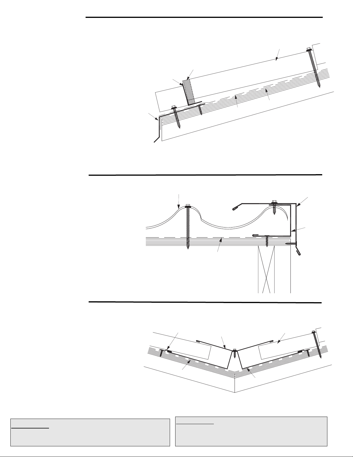
Eave Detail
Gable Detail
Valley Detail
1. In re-roofing applications: cut back and remove
existing shingles and drip edge to be flush with the
eave and gable lines. Apply new eave and gable
trim as detailed.
2. Install ATA-Shield underalyment. Install drip edge.
Install ATA-Guard over drip edge.
3. Install bottom closure angle beyond step,
approximately 4” from edge.
4. Install neoprene strip (optional) behind bottom
angle closure.
5. Fasten panel at low point making sure fasteners
penetrate solid substrate.
1. Install channel flush with gable edge, fasteners
2’ min. o.c. Seal at fastener penetrations.
2.Install first panel or cut last panel to fit and install.
Leave 1/4 - 1/2” space in channel.
3. Place gable trim cap over edge; fasten with
appropriate fasteners.
1. Install ATA-Shield** 19” up both side of the valley line.
2. Install valley sheet, fasten with valley clips
and appropriate fasteners.
3. Cut panel to angle, allow 2” to 3” from center of
valley, depending on length of panel.
4. Install panels on both sides of valley. Locate panel
fastener above valley pan.
5. Install cover (optional) with stitch screws.
Underlayments: ATA-Shield** is the recommended self adhesive
underlayment for eaves, sidewall and any critical areas exposed
to ice damming and extensive water run off.
Available in 65’-8” x 3’ 3-3/8” rolls. (200 sq. ft. per roll).
Underlayments: ATA-Guard* is a polyolefin based, 100% asphalt
free, high strength reinforced roofing underlayment for use on steep
slopes beneath metal roofing. 1000 sq. ft. per roll at 48” wide.
Bottom
Closure Angle
Eave Trim
Techo Tile Panel
Neoprene Closure
ATA-Shield
ATA-Guard
Techo Tile Panel
Valley Clip
ATA-Guard
Valley Cover
Gable Trim
J-Channel
Techo Tile Panel
ATA-Guard
Valley Pan
Page 3

Hip & Ridge Detail
Headwall Detail
Shed Ridge Detail
Hip and ridge applications are handled in the same manner
.
1. Install panels to meet the Hip/Ridge.
2. Fasten top closure angle and neoprene closure
(optional) to panel using #12 x 1” pancake screw.
3. Apply butyl tape to top of closure angle, set
ridge/hip cap in place, fasten with stitch screw.
4. Prior to installing the last ridge cap, cut it to size and
fasten the end plug to the ridge cap before installing.
At the Hip: place a hip base over the hip, fasten with clip
(HPC903). Install the panel to the center of the hip base. Install
closure angle, put sealant at the edge of the panel. Install hip cap.
Note: Do not cut any metal over an installed metal roof. Do not
use an abrasive saw for cutting metal. When cutting the panels on
the hips use a nibbler or a Tenryu steel - pro blade for
ferrous metals or equal. To prevent metal particles from falling on
the panel, turn it upside down when cutting. Remove all chips and
dust immediately from roof panels.
Install appropriate underlayment to the edge.
1. Depending on the wall treatment, cut a reglet
in the wall.
2. Install panel to headwall.
3. Fasten top closure angle and neoprene closure
(optional) on the panel.
4. Install headwall trim over the panel while insuring that
the perpendicular section is flush to the wall.
1. Install panel to edge of roof.
2. Fasten top closure angle and Neoprene Closure
(optional) to the panel, max. 5” from roof edge.
3. Put high quality sealant along curve of panel
and on top of closure angle.
4. Fasten with appropriate fasteners.
Hip Closure
Hip Cap
Techo Tile Panel
Hip Base
ATA-Guard
Ridge Cap
Top Neoprene Closure
Top Angle Closure
Techo Tile Panel
ATA-Guard
Counterflashing
Headwall Trim
Top Angle Closure
Techo Tile Panel
Appropriate
Anchor Screws
ATA-Guard
Shed Ridge Cap
Top Angle Closure
Techo Tile Panel
Appropriate
Fastener
ATA-Guard
Page 4

Pipe Detail
Step 1
Cut on the proper pipe
diameter marked on the
flashing.
Step 2
Position over pipe and slide
down the pipe.
Step 3
Apply polyurethane sealant
to the bottom of the base.
Step 4
Mold the flexible base to
the panel contours.
Step 5
Fasten with 1/4” x 1-1/8”
drilling fastener every 1-1/2”
around the base.
Pipe drawings provided by Triangle Fasteners
Tools and Rules:
Basic Equipment Required:
Tie-off ropes, safety harness, long level, ladders, scaffolding with
approved planking, extension cords with approved
ground plugs and services.
Additional Tools:
Metal folding tool, hammer, chalk line, measuring tape, metal cutting
tools - nibblers, drills, hacksaw, utility knife, pop-rivet gun, caulking
guns, layout and combination square, C clamps, sheet metal shears
(including RH, LH, straight and overhand). Power driven screw gun with
proper bits, depth-setting nosepiece, variable speed.
Choose the correct equipment and tools to do the job in a safe
manner. Wear safety gear and follow OHSA requirements.
Follow these simple rules:
1. Never cut the panels with an abrasive cut-off wheel or torch,
as this will damage the finish.
2. Do not weld the trim or panels.
3. Remove any small burrs left by cutting, screwing or drilling.
4. Remove protective masking immediately after trim is installed.
5. Caution should be taken when unloading the panels to
prevent damage.
6. Use appropriate screws for the type of underlayment and long
enough to fully penetrate and secure the panel.
7. The stored materials should be kept dry.
8. Do not cut on finished roof. Remove all drill spirals, chips and
dust immediately.
9. Seal neoprene closures and soft cell foam by applying
appropriate sealant to both surfaces.
10. Put appropriate sealant/butyle tape between overlapping trims.
11. Overlap trims in a manner not to impede the flow of water.
For further information or assistance, contact our Residential Product Support at 800-468-1441
©2007 ATAS International, Inc. All
rights reserved. Techo Tile is a
tradename of ATAS International, Inc.
ATAS International, Inc.
www.atas.com ~ info@atas.com
Corporate Office
6612 Snowdrift Road
Allentown, PA 18106
Sidewall Detail
1. Install ATA-Shield** below sidewall flashing and up
sidewall if possible.
2. Fasten channel with SWR8XX screws.
3. Fit and install panel into channel.
4. Install sidewall flashing prior to wall treatment or
cut a reglet and install counter flashing (not shown).
Note Regarding Trim Details
The applicaiton of flashing and trim requires a detailed approach. Consideration should be given to the roof’s geometry and course
it creates for water run-off. Location of gutters and the use of snow retention systems should also be considered. Proper planning
regarding the sequence of material overlap is critical. Sealants, such as butyl tapes and tripolymers, should be used at overlapping
trim edges, in conjunction with exposed fasteners, and to seal flashings and other ancillaries. All fasteners should be properly
tightened and not overdriven at an angle. Fasteners that are too loose can “back out” over time. An overdriven fastener may cause
a depression in the material, which becomes a collection point for standing water.
LAC220
Sidewall Trim
Techo Tile Panel
ATA-Guard
ATA-Shield
J-Channel
 Loading...