

Page 1
Panel
#1
Panel
#2
Panel
#3
Panel
#4
Panel
#8
Panel
#7
Panel
#14
Cut to
Fit
Panel
#15
Panel
#9
Panel
#5
Panel
#6
Panel
#10
Panel
#16
Panel
#17
Panel
#11
Panel
#18
Panel
#12
Panel
#19
Panel
#20
Panel #13
Cut to Fit
These edges
to fit into gable
utility cleat
First row
may vary to
obtain roof
symmetry
Clips
16” Nom.
5’-0”
Nom.
3’-0”
Nom.
Slope
See Gable
Detail on
Page 2
5'
3"
16" NOM.
3'
12" TYP.
16" NOM.
3"
12" TYP.
Installation Guide
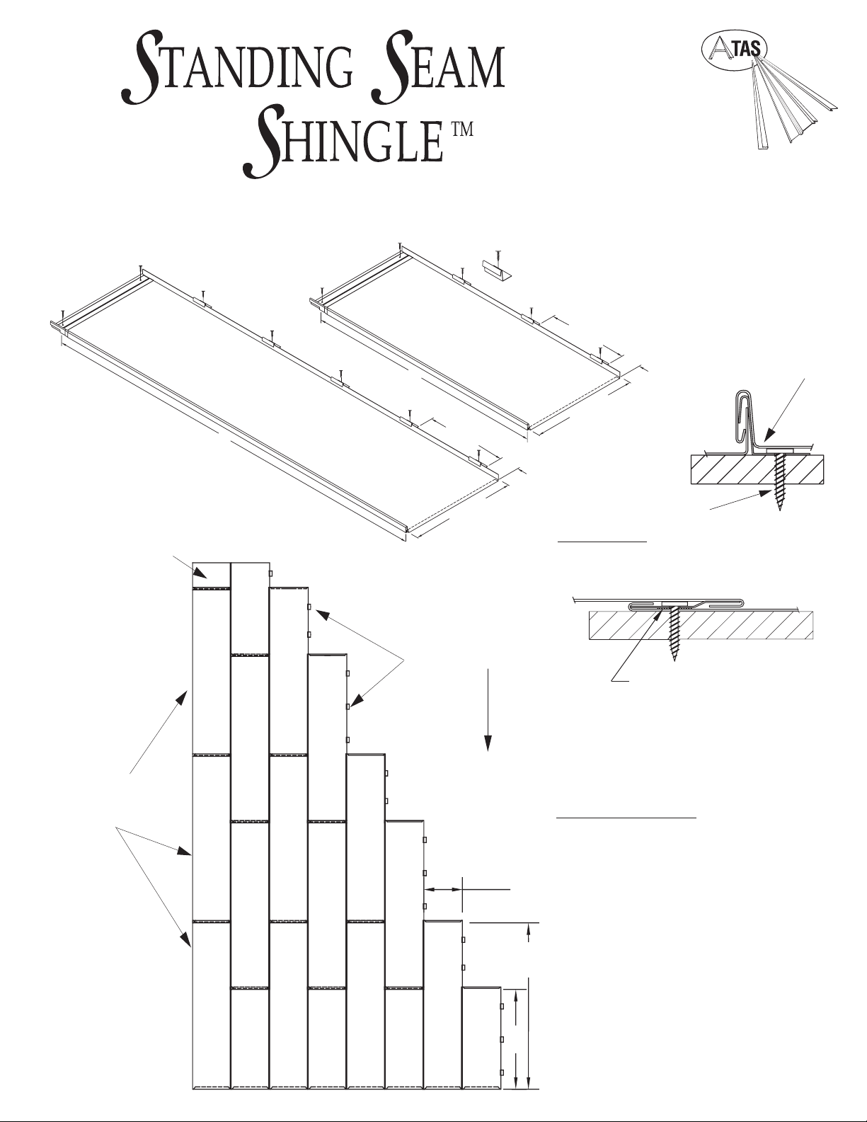
Factory-Applied Sealant
Between Cleat and Panel at
Fastener Location(s).
Panel
#10 x 1” Screw
Review and understand
complete guide be fore
beginning installation.
This guide has been prepared
as suggested details to
particular design conditions.
Each condition has cer tain
limitations to performance, aethetics
or economics. Professionals qualified to assess the
information regarding suitability for a specific project
should determine that the selection and installation
are made to their requirements. ATAS cannot assume
any responsibility for the actual selection and/or
installation of materials. The panels, flashings and trim
shown in this guide, illustrated over solid and plumb
substrate, assume that the structure has been
designed and prepared in accordance with local
building codes.
Clip Layout
Side Seam Detail
Locate 3 clips along the nom. 37 ⁄” long side and
5 clips along the 60 ⁄” side - see above.
Standing Seam Shingle Panels are available in
two sizes: 16" (nom.) wide by either 3' long (nom.
coverage) or 5' long (nom. coverage). Minimum
roof pitch is 4:12.
Panel Installation Details
Standing Seam Shingle is installed in a staggered
pattern, from eave to ridge, left to right. Start in
the bottom left corner of the roof plane with a 5'
panel. The pattern must stagger along eave line
with 5' and 3' panels. For panel sequence follow
numbered pattern to the left.
Panels are fastened to a solid substrate with side
clips spaced as shown and using a #10 screw.
Fasten at top of panel using two #10 screws per
panel through the factory mounted cleat.
Published panel width dimensions are to be considered
as nominal dimensions. Variations in overall coverage
may occur at installation due to typical manipulating of
panels during attachment to the roof assembly.
Page 2
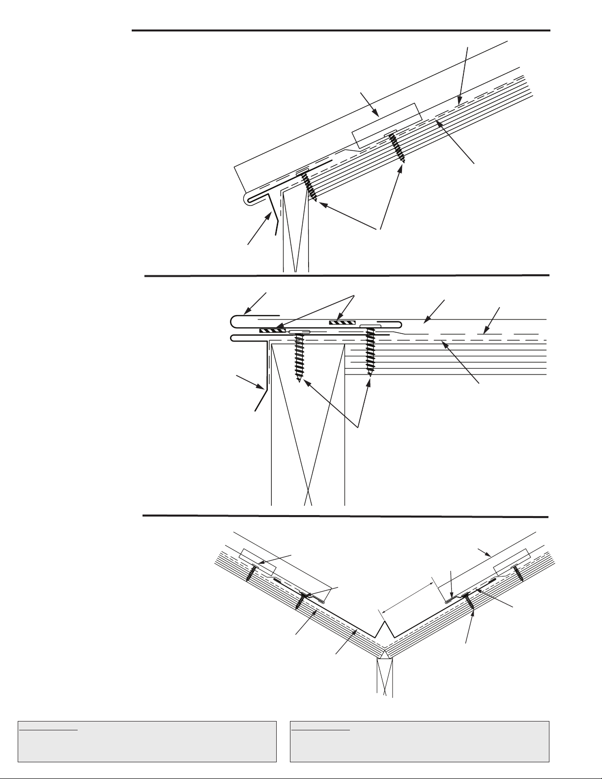
Eave Detail
Side Seam
Anchor Clip
ATA-Guard*
ATA -Shield**
#10 x 1” Screw
HSA112
Drip Edge
AT A-Guard*
#10 x 1” Screw
Shingle
HSA975 Joggle
Cleat
3”
AT A -Shield**
HSA800
Valley Pan
Butyl Tape
Clip & Fastener
ATA-Guard*
ATA -Shield**
#10 x 1” Screw
HSA112
Drip Edge
Shingle
Butyl Tape
HSA234 Gable
Utility Trim
1. In re-roofing applications: cut back and remove
existing shingles and drip edge to be flush with the
eave and gable lines, or as required to install
underlayment.
2. In all applications: apply ATA-Shield** along eave
and up the roof to a point at least 24” beyond outside
face of exterior wall.
3. Install drip edge against fascia trim. Space fasteners
at a maximum of 12” o.c. Overlap drip edge a
minimum of 2”.
4. Place ATA-Guard* on the roof, overlapping drip
edge.
5. Refer to gable and/or valley details as required
before installing panels.
6. Install panel by sliding lower flange over drip edge.
Gable Detail
1. Apply drip edge over ATA-Guard* at gable. Make
sure to overlap the drip edge at the eave line. Gable
side on top of eave trim.
2. Apply butyl tape to drip edge. Lay the gable trim
on top of drip edge as shown. Always start with the
lower section and overlap joints a minimum of 3”.
Fasten through butyl tape into solid substrate. Space
fasteners at 12” o.c. max.
3. Cut formed seam from shingle or cut it to width.
(To center panels on roof divide width of roof by 16,
divide leftover by 2 use that number as starting width
for first row of shingles)
4. Install panel by sliding lower flange over drip edge
and slip side into gable trim.
Valley Detail
1. Install ATA-Shield** 18” up both sides of the valley
line.
2. Always start with lower section. Install the valley
pan and fasten in conjunction with joggle (see step 3
below). Overlap valley pans at a minimum of 6”. Use
sealant between metals. Install ATA-Guard* 2” over
edge of valley pan.
3. Place joggle cleat on butyl tape 3” from middle of
valley pan and fasten through pan into substrate.
Space fasteners at 6” o.c. max.
4. Cut panel to size and angle, allowing for 1”
fold. Remove 1” from the formed seams on both sides
of panel; bend the panel 1” under to create a lip. Hook
lip into joggle cleat. Fasten panel with clip above
valley pan line.
Underlayments: ATA-Guard* is a polyolefin based, 100% asphalt free,
high strength reinforced roofing underlayment for use beneath
metal roofing on steep slope applications. 1000 sq. ft. per roll at 48”
wide.
Underlayments: ATA-Shield** is the recommended self adhesive
underlayment for eaves, sidewall and any critical areas exposed to ice
damming and extensive water run off. Available in 65’-8” x 39 ⁄” rolls
(200 sq. ft. per roll).
Page 3

Hip & Ridge Detail
AT A-Guard*
Shingle
#10 x 1” Screw
Sealant
HSA300 Ridge/Hip Cap
HSA930 Pocket
“Z” Closure
HSA930 Pocket
“Z” Closure
ATA-Guard*
Shingle
#10 x 1” Screw
Sealant
Appropriate
Anchor Fastener
Counterashing
HSA342
Shed Ridge
Tr im
ATA-Guard*
Painted Gasketed Screw
Support
Blocking
HSA930 Pocket
“Z” Closure
Sealant
Shingle
Hip and ridge applications are handled in the same manner.
1. Install ATA-Guard* over the hip/ridge line.
2. To locate pocket “Z” closure, utilize cap as template and
snap a line. Make sure that “Z” is spaced properly to allow
cap to lock onto pocket “Z”. Tack fasten front leg.
3. Cut shingle to length. Cut formed seams and legs back
1¼” to allow pan of panel to slide into pocket. Fasten
shingle through back leg of “Z” into solid substrate. Use 2
fasteners per panel.
4. Place continuous bead of sealant where the panel
meets the Pocket “Z” Closure.
5. Hook cap on to “Z”, fasten with pop-rivets 12” o.c. Do not
fasten consecutive caps together. Always start with the
lower section and overlap joints 6”, place sealant between
metals.
Ridge caps can accommodate standard ridge venting products.
Refer to venting manufacturer’s instructions and local building
code requirements.
Headwall Detail
Install ATA-Guard* to the roof and wall transition.
1. To locate pocket “Z” closure, utilize headwall trim as
template and snap a line. Make sure that “Z” is spaced
properly to allow headwall trim to lock into pocket “Z”. Tack
fasten front leg.
2. Cut shingle to length. Cut formed seams and legs back
1¼” to allow pan of panel to slide into pocket. Fasten
shingle through back leg of “Z” into solid substrate. Use 2
fasteners per panel. Hook headwall trim on “Z”, fasten with
pop-rivets and into wall with appropriate fasteners. Do not
fasten consecutive caps together but overlap them with
sealant between the metals.
3. Place continuous bead of sealant where the panel meets
the pocket “Z” Closure.
4. Install counter flashing into reglet over headwall
transition. Seal into reglet with appropriate sealant or place
wall treatment over headwall trim.
Shed Ridge Detail
1. Install ATA-Guard* over the edge of the peak. Put a 2x2
on top edge for support.
2. To locate “Z” closure, utilize shed ridge cap as template
and snap a line. Make sure that “Z” is spaced properly to
allow shed ridge trim to lock onto “Z”. Tack fasten front leg.
3. Cut shingle to length. Cut formed seams and legs back
1-1/4” to allow pan of panel to slide into pocket. Fasten
shingle through back leg of “Z”. Use 2 fasteners per panel.
Hook shed ridge cap on to “Z”, fasten with pop-rivets 12” o.c.
Do not fasten consecutive caps together but overlap them
with sealant between the metals.
4. Place continuous bead of sealant where the panel meets
the Pocket “Z” Closure.
5. Fasten shed ridge cap onto facade with painted gasketed
screws.
Page 4

Sidewall Detail
Counterashing
Appropriate
Anchor Fastener
Selant
HSA234 Gable
Utility Trim
Butyl Tape
#10 x 1” Screw
ATA -Shield**
Shingle
Clip & Fastener
HSA410
Sidewall Trim
1. Install ATA-Shield** along roof plane and up
sidewall.
2. Place sidewall flashing trim up against sidewall
and fasten with appropriate fastener. Place butyl
tape on sidewall trim as shown.
3. Place utility flashing trim into sidewall trim and
fasten. Lay another strip of butyl tape and install
panel into receiver of trim.
4. Install fastners at top edge of panel and through
trims into substrate. Attach side clips as required.
5. Place sealant in joint between trim pieces in 90°
angle. Install counterflashing over sidewall trim.
6. If the wall treatment is siding, it should lay over
the sidewall trim. If brick or stucco, a reglet should
be used with counterflashing to seal (as shown to
left). Be sure to seal reglet with appropriate
sealant.
Note Regarding Trim Details
The application of flashing and trim requires a detailed approach. Consideration should be given to the roof’s geometry and course it creates for
water run-off. Location of gutters and the use of snow retention systems should also be considered. Proper planning regarding the sequence of
material overlap is critical. Sealants, such as butyl tapes and tripolymers, should be used at overlapping trim edges, in conjunction with exposed
fasteners, and to seal flashings. All fasteners should be properly tightened and not overdriven at an angle. Fasteners that are too loose can “back out”
over time. An overdriven fastener may cause a depression in the material, which becomes a collection point for standing water.
Pipe Detail
Step 1
Cut on the proper pipe
diameter marked on the
flashing.
Pipe drawings provided by Triangle Fasteners
Tools and Rules:
Basic Equipment Required:
Tie-off ropes, safety harness, long level, ladders, scaffolding with
approved planking, extension cords with approved ground plugs
and services.
Position over pipe and slide
Additional Tools:
Metal folding tool, hammer, chalk line, measuring tape, metal
cutting tools - nibblers, drills, hacksaw, utility knife, pop-rivet
gun, caulking guns, layout and combination square, C clamps,
sheet metal shears (including RH, LH, straight and overhand).
Power driven screw gun with proper bits, depth-setting
nosepiece, variable speed.
Choose the correct equipment and tools to do the job in a
safe manner. Wear safety gear and follow OHSA
requirements.
Step 2
down the pipe.
Apply polyurethane sealant
to the bottom of the base.
1. Never cut the panels with an abrasive cut-off wheel or torch, as this will damage
the finish.
2. Do not weld the trim or panels.
3. Remove any small burrs left by cutting, screwing or drilling.
4. Remove protective masking immediately after trim and panels are installed.
5. Caution should be taken when unloading the panels to prevent damage.
6. Use appropriate screws for the type of underlayment and long enough to fully
penetrate and secure the panel.
7. The stored materials should be kept dry.
8. Do not cut on finished roof. Remove all drill spirals, chips and dust immediately.
9. Seal neoprene closures and soft cell foam by applying appropriate sealant to
both surfaces.
10. Put appropriate sealant/butyl tape between overlapping trims.
11. Overlap trims in a manner not to impede the flow of water.
Step 3
Mold the flexible base to the
Follow these simple rules:
Step 4
panel contours.
Fasten with ¼” x
fastener every 1½”
around the base.
Step 5
1 ⁄” drilling
For further information or assistance, contact our Product Support at 800.468.1441
Corporate Office - Allentown, PA 18106 www.atas.com (610.395.8445)
ATAS International, Inc.
LAT260 LRD0710
©2010 Accel Roofing Products. All rights reserved. Standing Seam Shingle is a trademark of ATAS International, Inc.
 Loading...