

Page 1
Installation Guide
TM
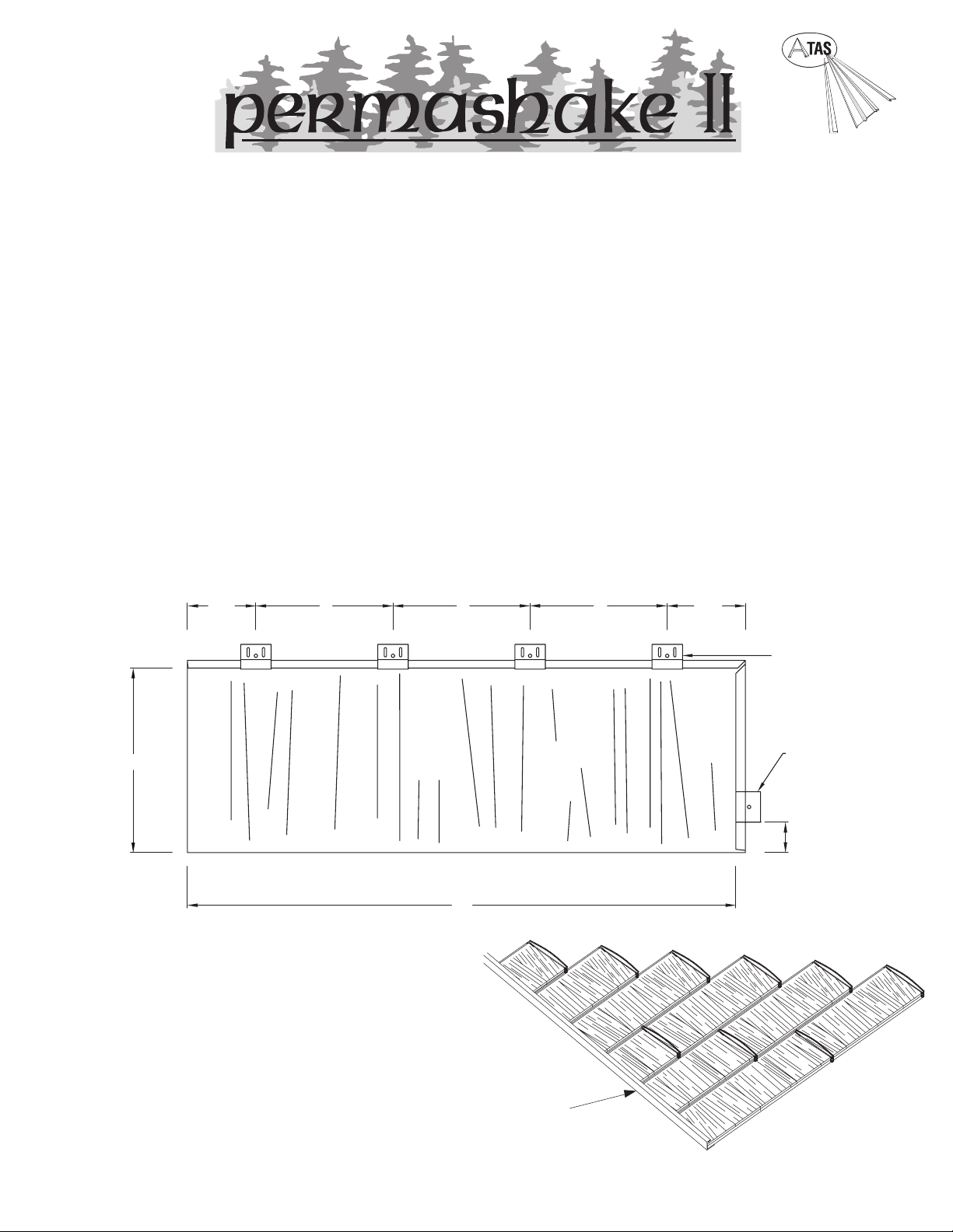
CHANNEL TRIM
TOP CLIPS
SIDE CLIP
4 ½”
9”
9” 9” 4 ½”
12”
36”
2”
ATAS International, Inc.
www.atas.com/permashakeII
484.221.6375
Review and understand complete guide before beginning
installation. This guide has been prepared as suggested
details to particular design conditions. Each condition has
certain limitations to performance, aesthetics or economics.
Professionals qualified to assess this information for a
specific project should determine that the selection and
installation are made to their requirements.
ATAS cannot assume any responsibility for the actual
selection, use and/or installation of materials. The panels,
flashings and trim shown in the guide, illustrated over a
solid and plumb substrate, assume that the structure has
been designed and prepared in accordance with local
building codes. Care should be taken during installation
not to damage panels and finish. May void product
warranty.
Published panel width dimensions are to be considered as
nominal dimensions. Variations in overall coverage may
occur at installation due to typical manipulation of panels
during attachment to the roof assembly.
Permashake II panels are simulated wood shakes
manufactured from 29 gauge steel with a Kynar 500® PVDF
or Hylar 5000® PVDF nish. They are available in 6 colors.
Panel coverage is 12” x 36”. Minimum recommended roof
pitch is 4:12.
There are twelve (12) Permashake II panels packaged per
carton. Approximately thirty-four (34) panels equal a square.
Panels are always installed left to right and should have a
minimum of four (4) top anchor clips and one (1) side anchor
clip.
PANEL INSTALLATION - In environments where ice and
water may dam, apply self-adhered roong underlayment in
accordance with local building codes. Then apply appropriate
underlayment over balance of roof. Snap a vertical and
horizontal line to square up the plane with the eave. Start
at the bottom left hand corner of the roof plane with a full
length panel. Install shingles in a left to right manner from
eave to ridge. See right for stagger method of installation.
Fasten panels to solid substrate with galvanized steel clips.
Manufacturer recommends the use of exterior grade #10-16 x
1 ½” wafer head screws.
STAGGER METHOD
Each course 12” to the left of the lower course.
Page 2
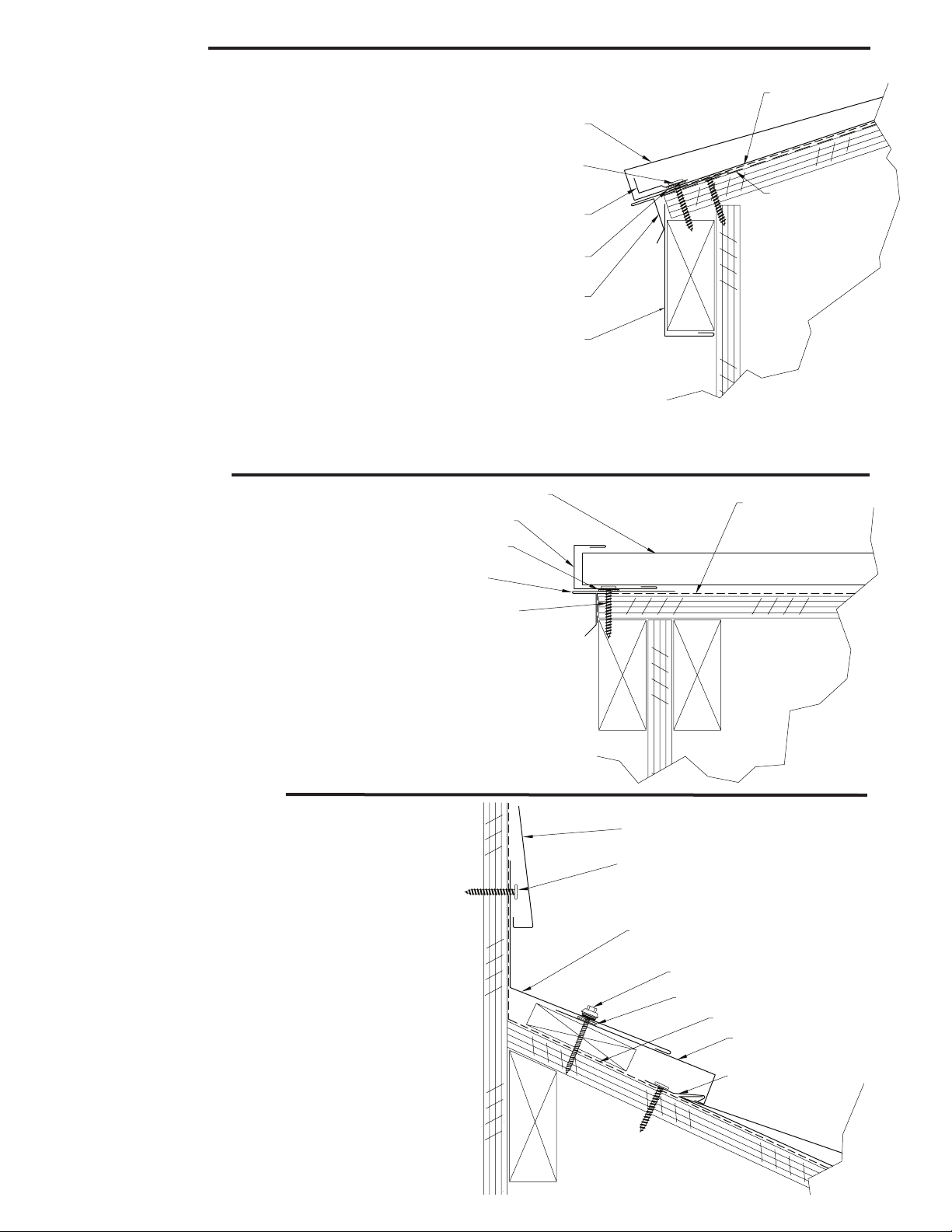
Eave Detail
WALL COVERING
BUTYL TAPE
ANCHOR CLIP
PERMASHAKE II PANEL
UNDERLAYMENT
2" HEX HEAD SCREW
HEADWALL TRIM
APPROPRIATE FASTENER
SELF-ADHERED
ROOFING
UNDERLAYMENT
FASCIA
DRIP EDGE
BUTYL TAPE
1 ½" WAFER HEAD SCREW
STARTER CLEAT
PERMASHAKE II PANEL
UNDERLAYMENT
UNDERLAYMENT
1 ½" WAFER
HEAD SCREW
DRIP EDGE
BUTYL TAPE
PERMASHAKE II PANEL
CHANNEL TRIM
1. When applying a re-roof application, cut back existing
shingles and drip edge as required to apply appropriate
underlaments.
2. Apply self-adhered roofing underlayment on roof deck
areas where ice & water damming can occur. Extend this
underlayment over fascia board. Install drip edge as tight as
possible against the fascia trim. Space fasteners at maximum
of 12” o.c. Overlap eave trim pieces a minimum of 3”.
3. Lay full width of underlayment (roofing felt or equivalent)
on top of the drip edge. Apply butyl tape on top of drip edge
and fasten starter cleat through butyl tape and eave trim into
substrate with front face up as shown at right.
4. Install panel only after the gable closure is installed (see
below). Install by sliding lower flanged edge between starter
cleat and drip edge. Square the panel in the J channel at the
gable edge and fasten with clips and exterior grade #10-16 x
1 ½” wafer head screws.
Gable Detail
1. Install drip edge over underlayment. Overlap on
top of drip edge at the eave.
2. Apply butyl tape along drip edge as shown to
the right. Lay the channel trim along the gable
edge. Overlap channel at a minimum of 2” to 4”
working upward from the eave. Fasten channel as
shown at right.
3. Align the first shingle into the J channel and
snap a line across the roof plane. (See panel
installation section)
Headwall Detail
1. Install metal shingles up to the headwall. Shim the last
row of panels if necessary as shown at right.
2. Lay headwall trim over the shingles while insuring that the
vertical section is flush against the headwall. Use double
sided butyl tape between the panel and trim assemblies.
3. Fasten through butyl tape and shingle into solid substrate.
Use #10 x 2” long gimlet point screw with 5/16” cast zinc
color matched hex washer head and EPDM washer at 24” o.c.
4. Apply wall covering over the headwall trim as required, or
install wall paneling.
1
2
Exterior grade #10-16 x 1 ½” wafer head screw
#10 x 2” long gimlet point screw with 5/16” cast zinc color matched hex washer head and EPDM washer
Page 3

Hip & Ridge Detail
CUT AND FOLD PANEL EDGE
IN VALLEY TO CLOSE END.
POP RIVET
SELF-ADHERED ROOFING
UNDERLAYMENT
VALLEY PAN
UNDERLAYMENT
ANCHOR CLIP
1 ½" WAFER HEAD SCREW
PERMASHAKE II PANEL
RIDGE CAP BENT TO
REQUIRED ANGLE AND TWO
INTERLOCKING TABS BENT UP
FOR CLIP ATTACHMENT.
(HIP CAP SIMILAR)
LOCATE CLIPS HERE
SHORT RIDGE
CAP PIECES
CHANNEL TRIM
PERMASHAKE II PANEL
PREVAILING WIND
DIRECTION
LAP
START APPLYING
RIDGE CAP SHINGLE
AT THIS END
SHORT HIP CAP PIECES
PANELS CUT
TO MEET AT
HIP LINE
HIP LINE
UNDERLAYMEN
T
Hip and ridge applications are handled in
the same manner.
1. Install roof panels to meet at hip or
ridge. (Depending on roof geometry
and run of roof, the top panel may have
to be cut along the length of panel.)
2. Lay a 6” strip of closure tape across
panels at hip/ridge line.
3. Lay cap on roof and secure the cap
with clips and screws, (2) per piece.
Ridge caps can accommodate standard
ridge venting products. Refer to venting
manufacturer's instructions and local
building code requirements.
Note: For hip applications, fasten the caps
with clips at the high point on the shingle
in order to avoid dimpling, and make sure
the clip and screw penetrates the cap
through the closure into the solid
substrate.
Valley Detail
1. Install self-adhered roofing underlayment
18” up both sides of the valley line.
2. Install the valley pan and clip fasten
through the substrate at 24” o.c.
3. Measure required panel to length to come
within 3” of center of valley.
4. Cut and fold panel on diagonal to create a
solid end and fasten with stainless steel color
matched pop rivet to hold in place.
5. Lay shingles onto the valley pan
maintaining at least 3” clearance from the
valley’s center and fasten with clips outside
the valley pan.
1
Exterior grade #10-16 x 1 ½” wafer head screw
2
#10 x 2” long gimlet point screw with 5/16” cast zinc color matched hex washer head and EPDM washer
Page 4

Shed Ridge Detail
WALL COVERING
SELF-ADHERED ROOFING
UNDERLAYMENT
PERMASHAKE II PANEL
SIDEWALL CAP
STEP FLASHING
APPROPRIATE FASTENER
UNDERLAYMENT
2" HEX HEAD SCREW
SHED RIDGE
PERMASHAKE II PANEL
1 ½" WAFER HEAD SCREW
ANCHOR CLIP
SHIM
Sidewall Detail
1. Install metal shingles up to the shed ridge peak.
Shim panels if necessary as shown at left.
2. Place double sided butyl tape just inside hem of
Shed Ridge Trim. Fit trim to peak. Fasten through tape
and shingle into solid substrate. Use #10 x 2” long
gimlet point screw with ⁄” cast zinc hex washer head
and EPDM washer at 24” o.c.
3. Fasten Shed Ridge Peak Trim to fascia with #10 x 2”
long gimlet point screw with ⁄” cast zinc color
matched hex washer head and EPDM washer at 24” o.c.
1. Install self-adhered roofing underlayment along roof plane
and up sidewall.
2. Install step flashing tight against the sidewall.
3. Install the panel up to the wall. Fasten the panel clip as close
to the wall as possible without penetrating the step flashing.
4. Install the sidewall flashing and fasten in place.
5. If the wall treatment is siding, it should lay over the sidewall
trim. If brick or stucco, a reglet should be used with counter
flashing to seal. Be sure to seal reglet.
Note: Step flashing is designed to drain at the eave. The panel
that is attached to the eave at the gable end should be notched
to allow water to drain out.
Note Regarding Trim Details
The application of flashing and trim requires a detailed approach. Consideration should be given to the roof’s geometry and the course it creates for water runoff. Location of gutters and the use of snow retention systems should also be considered. Proper planning regarding the sequence of material overlap is critical.
Sealants, such as butyl tape and tripolymers, should be used at overlapping trim edges, in conjunction with exposed fasteners and to seal flashings. All fasteners
should be properly tightened and not over driven or at an angle. Fasteners that are too loose can “back out” over time. An over driven fastener may cause a
depression in the material, which becomes a collection point for standing water.
Basic Equipment Required:
Tie-off ropes, safety harness, long level, ladders,
scaffolding with approved planking, extension cords
with approved ground plugs and electrical services.
Additional Tools:
Metal folding tool, hammer, chalk line, measuring tape,
metal cutting tools - nibblers, drills, hacksaw, utility knife,
pop-rivet gun, caulking guns, layout and combination
square, C clamps, sheet metal shears (including RH, LH,
straight and overhand). Power driven screw gun with
proper bits, depth-setting nosepiece, variable speed.
Choose the correct equipment and tools to do the
job in a safe manner. Wear safety gear and follow
OHSA requirements.
1
Exterior grade #10-16 x 1 ½” wafer head screw 2 #10 x 2” long gimlet point screw with 5/16” cast zinc color matched hex washer head and EPDM washer
©2011 ATAS International, Inc. All rights reserved. PermashakeTM II is a trademark of ATAS International, Inc. ATAS reserves the right to modify, eliminate and/or change its products without prior notification. ATAS cannot assume any
responsibility for the actual selec tion, use and/or installation of materials. The structure should be designed and prepared in accordance with local building codes. Warr anty no t valid without registr ation. LRD0511 LAT089
Tools and Rules:
1. Never cut the panels with an abrasive cut-off wheel or torch, as this will damage the finish.
Follow these simple rules:
2. Do not weld the trim or panels.
3. Remove any small burrs left by cutting, screwing or drilling.
4. Remove protective masking immediately after trim and panels are installed.
5. Caution should be taken when handling the panels to prevent damage.
6. Use appropriate screws for the type of underlayment and long enough to fully penetrate and secure the panel.
7. The stored materials should be kept dry.
8. Do not cut on finished roof. Remove all drill spirals, chips and dust immediately.
9. Seal neoprene closures and soft cell foam by applying appropriate sealant to both surfaces.
10. Put appropriate sealant/butyl tape between overlapping trims.
11. Overlap trims in a manner not to impede the flow of water.
 Loading...