

Page 1
Installation Guide
Review and understand complete
guide before beginning installation.
This guide has been prepared as
suggested details to particular design
conditions. Each condition has certain limitations to
performance, aethetics or economics. Professionals
qualified to assess this information for a specific project,
should determine that the selection and installation are
made to their requirements. ATAS cannot assume any
responsibility for the actual selection and/or installation of
materials. The panels, flashings and trim shown in this
guide are illustrated over solid and plumb substrate. It is
assumed that the structure has been designed and
prepared in accordance with local building codes.
NOTE : This guide to be used for installations with a
roof slope of 2:12 or greater only on a solid
substrate. Consult factory for all other installations.
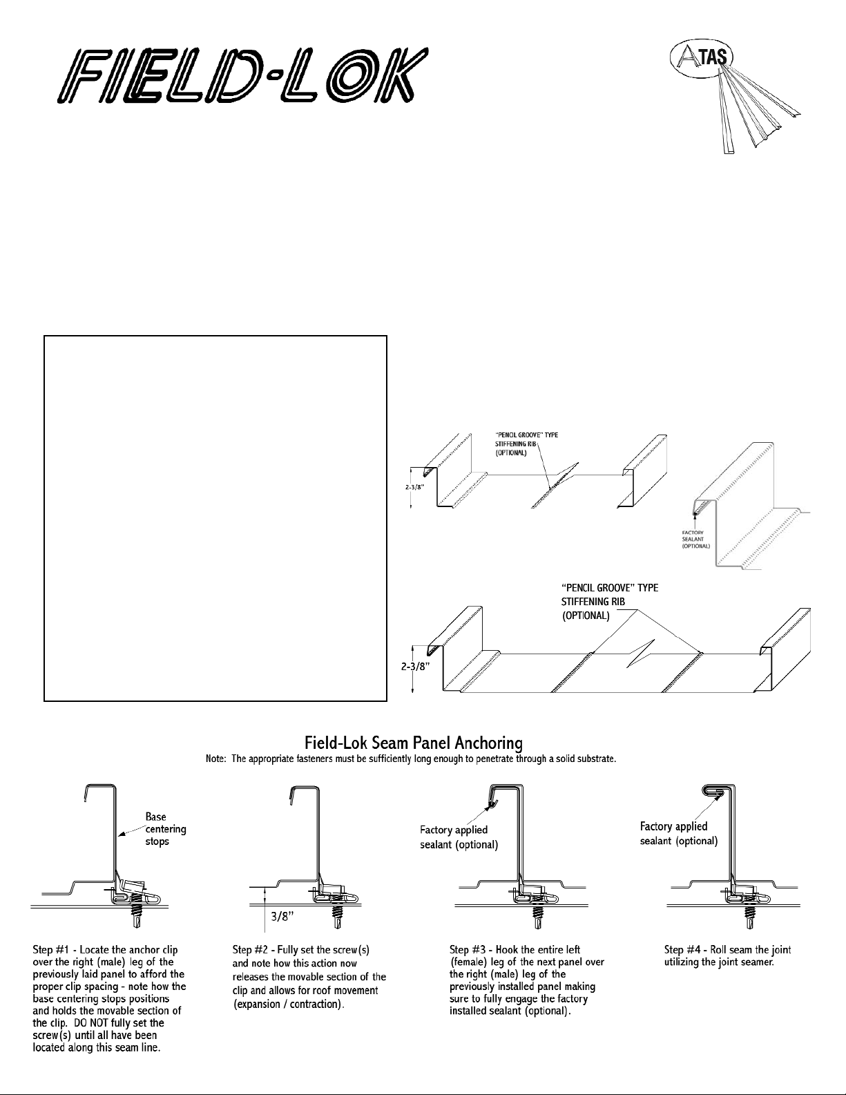
Field-Lok Panel has extra strength, extra height - field seamed
panel. Installed with concealed clips and fasteners and a
mechanical seamer in a tri-fold lock-in application. Panels are
available in smooth or embossed texture in 30 standard ATAS
colors are available with premium KYNAR 500
®
or HYLAR 5000
®
finish. Stiffening ribs are optional.
13 3/4” (FLS137) and 18” (FLS180) wide
FLS Panel
FLS180
FLS137
ATAS Field-Lok seam roof panels are typically designed for
low slope roofing with slopes of 3:12 and below. ATAS FLL
and FLM series are commonly used on slopes of 1.5/12 to
3:12 while our FLN and FLS series are commonly used on
slopes of .5/12 through 3:12. At slopes below 2:12 the use of
either factory or field applied sealant within the panel
interlock is recommended.
Field-Lok panels require the contractor to rent a fieldseaming machine designed for the specific panel profile and
gauge. These machines field form the panel-to-panel
connection and clip-to-panel connection. These on site seam
forming machines are relatively heavy. Extreme care should
be taken when using these machines in steep slope
applications. In addition, the primary design consideration
with mechanically seamed panels is functional
waterproofing. Often the mechanical seaming in the field can
cause clip read through or telegraphing and can be seen
visually when used in steep slope roofing applications. This
read through of the clip is considered to be aesthetic only
and not a structural defect of the panels and therefore not a
cause for rejection of the materials. Some slight surface
abrasion may be evident on the finish of the panels after
field seaming of the panels.
Page 2
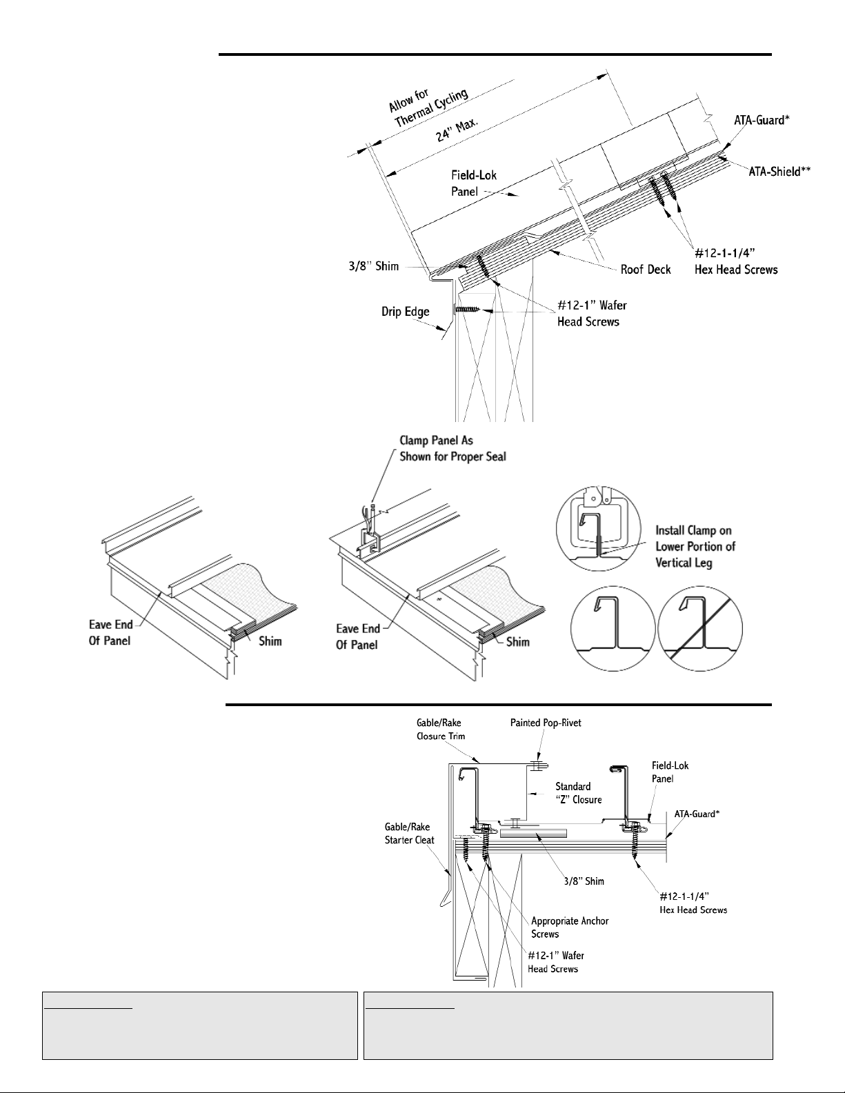
Eave Detail
Gable Detail
1. Apply ATA-Shield** along eave and up the roof
to a point at least 24” beyond outside face
of exterior wall.
2. Install 3/8” shim at eave.
3. Install drip edge against fascia trim.
Lay ATA-Guard*over eave trim.
4. Trim (cut) both seams back to allow for turn down.
Install panel by sliding lower flanged edge
over drip edge.
5. See below for proper panel sidelap installation.
General Note: Before any installation be sure to lay
ATA-Shield**in all areas where ice & water can occur.
ATA-Guard or appropriate underlayment should be
installed over the entire roof.
1. Install underlayment to gable edge.
Place 3/8” shim as shown.
2. At gable start detail, install gable trim starter cleat
with appropriate fasteners at 2’-0” into fascia board.
3. At end gable, cut panel to appropriate width to
allow room for clips at gable end. If panel cut off is
3” or wider install cut off portion of panel
underneath last panel w/ butyl tape applied in
between the two panels and install clips before
installing gable assembly.
4. Apply double-faced butyl sealant as circled in
sketch. Fasten “Z” closure to panel with pop-rivets.
5. Install starter cleat at end detail same
as start detail.
6. At both ends snap gable/rake trim over starter
cleat and “Z” closure to-Lok into place. Pop-rivet
these two pieces together with one pop-rivet
per trim length.
Underlayments: ATA-Shield** is the recommended self adhesive
underlayment for eaves, sidewall and any critical areas exposed to ice
damming and extensive water run off.
Available in 65’-8” x 39-3/8” rolls (200 sq. ft. per roll).
Underlayments: ATA-Guard* is a polyolefin based, 100%
asphalt free, high strength reinforced roofing
underlayment for use beneath metal roofing on steep
slope applications. 1000 sq. ft. per roll at 48” wide.
PANEL SIDELAP
Page 3
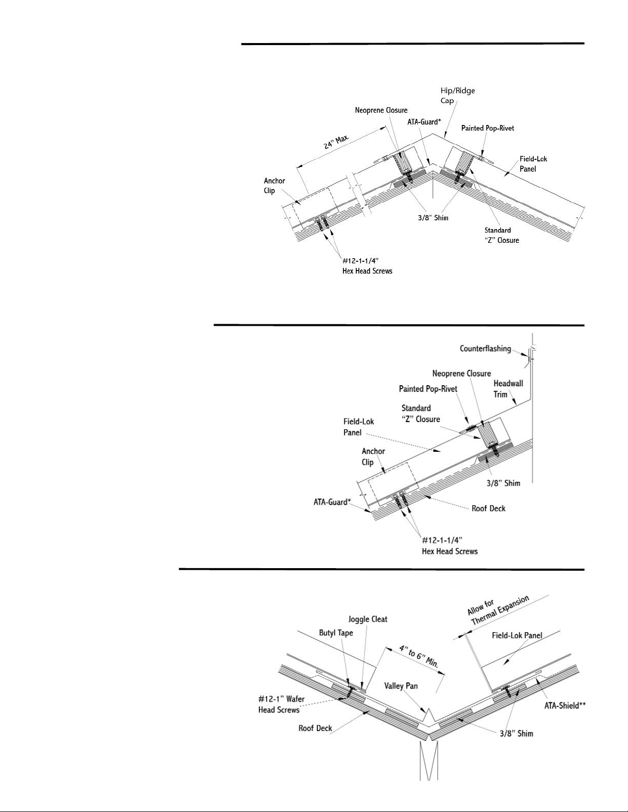
Hip & Ridge Detail
Headwall Detail
Valley Detail
Hip and ridge applications are handled
in the same manner.
1. Install underlayment to roof edge.
Place 3/8” shim as shown.
2. Cut “Z” closure to fit between seams and install in
butyl tape. Fasten through 3/8” shim to secure
panel (Use 4 fasteners on 13 3/4”, 5 on 18” )
3. Seal neoprene strips into “Z” closures .
4. Snap hip/ridge cap over “Z” closures for it to lock
into place. Pop-rivet one side only to allow for
expansion and contraction.
Notes:
* Trim must be pop-riveted to Z in at least one
location to control thermal movement.
* Unless otherwise specified, all fasteners for trim
components should be spaced at 2’-0” o.c.
* Install splice plates at ridge cap joints. Pop rivet
splice to one end of ridge cap to allow for
expansion and contraction.
.
1. Install underlayment to roof edge.
Place 3/8” shim as shown.
2. In standard headwall situation (without venting),
run underlayment from roof plane up headwall.
Install panels up to headwall.
3. Fasten “Z” closure in bed of sealant at top of
panel. Fasten through 3/8” shim to secure panel.
(Use 4 fasteners on 13 3/4”, 5 on 18” )
4.Seal neoprene closure into “Z” closure.
5. Install headwall transition over “Z” closure.
6. Apply counterflashing over the headwall trim,
as required.
1. Install ATA-Shield** approximately 18” up
both sides of the valley line.
2. Place 3/8” shim as shown.
3. Lay valley pan in valley center. Locate joggle
cleat at 4” to 6” from valley center.
4. Install joggle cleat. Fasten 6” o.c. through
butyl tape and pan into 3/8” shim and substrate.
5. Turn under edge of panel to slide into
joggle cleat. Fasten with clips at 2’-0” o.c.
Page 4

Pipe Detail
Step 1
Cut on the proper pipe
diameter marked on the
flashing.
Step 2
Position over pipe and slide
down the pipe.
Step 3
Apply polyurethane sealant to
the bottom of the base.
Step 4
Mold the flexible base to
the panel contours.
Step 5
Fasten with 1/4” x 1-1/8” drilling
fastener every 1-1/2” around
the base.
Pipe drawings provided by Triangle Fasteners
Tools and Rules:
Basic Equipment Required:
Tie-off ropes, safety harness, long level, ladders, scaffolding with
approved planking, extension cords with approved ground plugs
and services.
Additional Tools:
Metal folding tool, hammer, chalk line, measuring tape, metal cutting
tools - nibblers, drills, hacksaw, utility knife, pop-rivet gun, caulking
guns, layout and combination square, C clamps, sheet metal shears
(including RH, LH, straight and overhand). Power driven screw gun
with proper bits, depth-setting nosepiece, variable speed.
Choose the correct equipment and tools to do the job in a safe
manner. Wear safety gear and follow OHSA requirements.
Follow of few simple rules:
1. Never cut the panels with an abrasive cut-off wheel or torch, as this will
damage the finish.
2. Do not weld the trim or panels.
3. Remove any small burrs left by cutting, screwing or drilling.
4. Remove protective masking immediately after trim is installed.
5. Caution should be taken when unloading the panels to prevent damage.
6. Use appropriate screws for the type of underlayment and long enough to
fully penetrate and secure the panel.
7. The stored materials should be kept dry.
8. Do not cut on finished roof. Remove all drill spirals, chips and dust immediately.
9. Seal neoprene closures and soft cell foam by applying appropriate sealant
to both surfaces.
10. Put appropriate sealant/butyl tape between overlapping trims.
11. Overlap trims in a manner not to impede the flow of water.
For further information or assistance, contact our Technical Product Support at 800-468-1441
©2007 ATAS International. All rights
reserved. Field-Lok is a tradename
of ATAS International, Inc.
ATAS International, Inc.
Corporate Office
Allentown, PA 18106
www.atas.com info@atas.com
Sidewall Detail
1. Install underlayment to sidewall.
Place 3/8” shim as shown.
2.Install metal panel up to within
1” of the sidewall.
3. Fasten “Z” closure in bed of butyl
sealant at top of panel as shown.
4. Fasten sidewall trim over “Z”
closure to face of sidewall.
5. Apply counterflashing over the
sidewall trim, and seal into reglet.
NOTE: Trims should be fastened
to substrate and sidewall using a
#12 x 1” wafer head screw.
Note Regarding Trim Details
The applicaiton of flashing and trim requires a detailed approach. Consideration should be given to the roof’s geometry and course it
creates for water run-off. Location of gutters and the use of snow retention systems should also be considered. Proper planning regarding
the sequence of material overlap is critical. Sealants, such as butyl tapes and tripolymers, should be used at overlapping trim edges, in
conjunction with exposed fasteners, and to seal flashings. All fasteners should be properly tightened and not overdriven at an angle.
Fasteners that are too loose can “back out” over time. An overdriven fastener may cause a depression in the material, which becomes
a collection point for standing water.
(610) 395-8445
 Loading...